EP0995552A2 - Bolzensetzgerät - Google Patents
Bolzensetzgerät Download PDFInfo
- Publication number
- EP0995552A2 EP0995552A2 EP99124281A EP99124281A EP0995552A2 EP 0995552 A2 EP0995552 A2 EP 0995552A2 EP 99124281 A EP99124281 A EP 99124281A EP 99124281 A EP99124281 A EP 99124281A EP 0995552 A2 EP0995552 A2 EP 0995552A2
- Authority
- EP
- European Patent Office
- Prior art keywords
- bolt
- piston
- guide
- setting tool
- housing
- Prior art date
- Legal status (The legal status is an assumption and is not a legal conclusion. Google has not performed a legal analysis and makes no representation as to the accuracy of the status listed.)
- Granted
Links
Images




Classifications
-
- B—PERFORMING OPERATIONS; TRANSPORTING
- B25—HAND TOOLS; PORTABLE POWER-DRIVEN TOOLS; MANIPULATORS
- B25C—HAND-HELD NAILING OR STAPLING TOOLS; MANUALLY OPERATED PORTABLE STAPLING TOOLS
- B25C1/00—Hand-held nailing tools; Nail feeding devices
- B25C1/08—Hand-held nailing tools; Nail feeding devices operated by combustion pressure
- B25C1/10—Hand-held nailing tools; Nail feeding devices operated by combustion pressure generated by detonation of a cartridge
- B25C1/14—Hand-held nailing tools; Nail feeding devices operated by combustion pressure generated by detonation of a cartridge acting on an intermediate plunger or anvil
-
- B—PERFORMING OPERATIONS; TRANSPORTING
- B25—HAND TOOLS; PORTABLE POWER-DRIVEN TOOLS; MANIPULATORS
- B25C—HAND-HELD NAILING OR STAPLING TOOLS; MANUALLY OPERATED PORTABLE STAPLING TOOLS
- B25C1/00—Hand-held nailing tools; Nail feeding devices
- B25C1/08—Hand-held nailing tools; Nail feeding devices operated by combustion pressure
- B25C1/10—Hand-held nailing tools; Nail feeding devices operated by combustion pressure generated by detonation of a cartridge
- B25C1/18—Details and accessories, e.g. splinter guards, spall minimisers
- B25C1/188—Arrangements at the forward end of the barrel, e.g. splinter guards, spall minimisers, safety arrangements, silencers, bolt retainers
Definitions
- the invention is based on a bolt-actuating device with which Help a fastener, usually in the form of a nail or bolt, can be placed.
- the bolt gun contains a propellant piston which is driven by the propellant gases after ignition of the propellant cartridge is driven and drives in the bolt.
- Such devices are used to shoot assembly elements used on hard surfaces, e.g. steel or Concrete.
- Trial shots are made to find out which one Propellant charge the correct result can be achieved.
- the hardness of the surface also within a wall can change, also leads to the setting of test shots and the use of different levels of propellant charge desired result.
- the invention has for its object a bolt-driving tool to improve in terms of ease of use. It should be possible with the device, ideally with only one Size of propellant without trial shots fasteners to be able to place on all types of surfaces.
- the invention proposes a bolt-setting tool with the features mentioned in claim 1.
- Bolt-setting tools must comply with certain regulations, which are intended to prevent misuse of the fastener driving tool.
- One of these regulations states that the device only then can be triggered when it is applied with a certain contact pressure pressed against the surface to be attached becomes.
- the bolt guide is usually used for this.
- the invention now proposes in training that the Damping element with the front end of the bolt guide connected is. When pressing against the one to be fastened Material and when the driving piston hits the pin guide, if this is axially displaceable, then here practically no pressure point arise.
- a rubber element for example, can be used as the damping material or an element made of another elastomer material be, for example butyl rubber or fluorine rubber. Furthermore, fiber-reinforced material, a metal web or a similar elastically deformable material be used.
- the damping element as a ring element between two ring parts forming the bolt guide are inserted and connected to them. Then here is the damping element not arranged at the front end of the bolt guide, it but works with the damping of the blow and also with the Damping the recoil in the same good way.
- the bolt pushing device can be designed in this way be that the bolt guide with which the damping element is connected, is axially displaceable.
- the damping element is designed such that it is under axial pressure radially expanded. This not only leads to damping in axial action, but can also be used become, by limiting the deformability To limit the damping and the damping path.
- the invention proposes that the damping element is vulcanized onto the bolt guide.
- the bolt guide thus forms a single component.
- the invention proposes that the damping element can be arranged so that it with his radial outside of a cylindrical wall of the housing is arranged opposite.
- the damping element can then interact with this wall when it is applied, for example in that the wall deformability limited of the damping element.
- the radial outside of the damping element of the cylindrical wall a small to no radial distance having.
- the damping element then serve a forward blow the pin guide by jamming against the cylindrical Wall of the housing or a housing or magazine part slow down.
- the bolt-setting tool provided by the invention leads to that the propulsion of the fastener at the end of the stroke the driving piston is reliably braked strongly so that it possible, the fastener always with the maximum To drive in propellant charge.
- This has the advantage that the fastener with a softer surface with a larger one Speed is driven in than on hard ground, but does not penetrate the assembly material. By the higher driving speeds, even with harder ones Material can be reached, the resilience improves the connection.
- the device does not need from the user using a handwheel in any other way on the respective To be set underground.
- Bolt setting device a braking element for braking the piston on End of its pushing motion.
- This braking element can be constructed in a similar or the same way as the damping element.
- the braking element stops the piston and transmits its energy on the case. This can happen that it expands and thereby faces each other radially jammed the outer wall.
- the piston guide has an inward flange Has system of the braking element.
- the housing a bracket part which is essentially the handle and has the cartridge holder, and a second housing part be built up of the piston guide, the piston and the Has bolt guide.
- This second housing part can be opposite the bracket part to be axially movable, wherein a recoil damping element is provided between the two parts is. This is the recoil that occurs during the setting process subdued so that it is not fully on the operator's hand is transmitted.
- the bolt gun a return spring made of elastic deformable material, in particular made of elastomer material, has that after setting the fastener Pushes the driving piston back.
- This characteristic of the spring made of elastomer material can also independently according to the invention of the presence of that mentioned in claim 1, be elastically deformable damping element.
- Usual driving pistons have a long, relatively narrow one Shank, the free end with the head of the fastener cooperates.
- the spring is designed as a sleeve that the shaft of Driving piston surrounds.
- the sleeve is easily deformable trained, it can for example also be designed as a bellows his. The forces that push the piston back are relatively low.
- the spring as a compression spring in the space between the pin guide and to arrange the driving piston. It is also possible, the driving piston with one that extends beyond the combustion chamber rear extension and the Arrange return spring in a second room.
- the return spring can in particular as a compression spring from one Elastomeric material to be formed. Therefore, it always becomes stressed so that the risk of tearing, such as for example under a tensile load. Even if their shape is partially destroyed, that is Spring is still present as an elastic material, so that a certain spring action is still achieved.
- the piston is lateral through slots in the piston guide or the housing Approaches on which the return springs attack, in which case they are also designed as tension springs could be.
- a return spring designed as a tension spring can, for example be formed by a ring made of elastomer material.
- the spring can be made from one another connected individual layers.
- This individual Layers can either be the same or one similar material exist.
- the layer structure can do this serve the spring against lateral displacement or lateral Secure buckling.
- the layers of different Materials consist, for example, of alternating harder and softer materials.
- the spring is layered from one build relatively hard and a relatively soft material, for example from hard washers and soft rings.
- the harder washers can be used as a braking element serve for the propellant piston, while the softer layers form the return spring. This will make it possible Brake element and the return spring as a single component to manufacture.
- the bolt gun shown in Fig. 1 contains a housing 1 with an axially aligned receiving mechanism Part and a side handle 2.
- the Handle 2 is designed as a bow handle. It contains a deduction 3rd
- the housing 1 contains a cylindrical interior in which a driving piston guide 4 in the axial direction around a certain one Amount is guided.
- the movability the driving piston guide 4 serves to secure the device against abuse and the supply of cartridges.
- a driving piston 5 is axially displaceable in the driving piston guide 4 arranged.
- the driving piston 5 contains one here disc-like part 6 with an enlarged diameter, the the inside 7 of the cylindrical inner opening of the driving piston guide 4 is present.
- the disc part 6 is one at the end cylindrical driving piston shaft 8 arranged.
- the stepped piston is also without the step, i.e. without the disk-like, enlarged part can be used.
- a bolt guide 9 in the form of a in the housing 1 Guide sleeve arranged.
- This pin guide 9 contains one first, cylindrical, engaging in the interior of the piston guide 4 Part and a second, through the face 10 of the housing outwardly extending part. Both parts, the different in the illustrated embodiment Have diameters, but this is not necessary by a radially projecting flange 11 from each other discontinued.
- the flange 11 is in an annular groove 12 of the housing 1 arranged, the axial extent of which is greater is than the thickness of the flange 11. This allows the bolt guide 9 moved in the housing by a certain distance become.
- Face 13 of the flange 11 is the free face the driving piston guide 4.
- the inner opening 14 of the pin guide 9 is used for receiving and holder of the fastener 15, for example in Shape of a nail or bolt.
- a Ring element 16 made of elastomer material, the outer diameter the inner diameter of the piston guide 4 approximately is the same and its inner diameter is slightly larger than that Outside diameter of the bolt part 8 of the driving piston 5 is.
- the bolt guide 9 contains the material to be fastened on it 17 facing end continuing the bolt guide 9 Damping element 18, which is also a ring element made of an elastomer material and with the bolt guide 9 is firmly connected, for example by vulcanization on the face. This forms the pin guide 9 together with the damping element 18 a single component.
- the device is operated as follows. After inserting the fastener 15 in the bolt guide 9, the device of the User pressed against the material to be fastened 17. This pressure is transferred to the bolt guide 9, the With the help of the flange 11 pushes the piston guide 4 into the device. This leads to a not to be described in more detail Way, the cartridge chamber 19 in the rear part of the driving piston guide 4 via the ready propellant powder cartridge, and the firing pin spring is tensioned. After triggering the trigger 3, the propellant charge is fired and the propelling piston 5 moved forward. The fastener 15 will thereby through the material 17 to be fastened into the Underground 20 driven.
- the driving piston 5 runs on it as a piston brake acting ring element 16. This is compressed and expanded thereby radially on, so that it is relatively stationary in the piston guide 4 is axially fixed. The residual energy will thereby transferred to the piston guide 4 and possibly the housing 1. Due to the buffer stroke and a partial axial movement the piston guide 4 becomes part of the kinetic energy transferred to the pin guide 9. This residual energy of Bolt guide 9 is then received by the damping element 18.
- Fig. 1 shows the axial position of the bolt guide 9 in one State in which you cannot fire. At the moment of firing, however, the pin guide 9 is shifted to the right, so that the damping element 18 within the front part of the housing. With axial loading of the damping element 18, this is also expanded radially, which leads to a jamming that also acts in the axial direction between the pin guide 9 and the housing 1 leads.
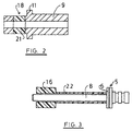
- the damping element 18 arranged at the outer end of the pin guide 9 2 shows an embodiment of the bolt guide 9, in which the damping element 18 as a ring element 21 between two parts of the otherwise identical bolt guide 9 is arranged.
- the ring element is 21 with its outer and inner dimensions on the bolt guide 9 matched.
- Fig. 3 shows again a side view of the driving piston 5 with its shaft 8 in the same arrangement as in the Fig. 1. Also the ring element 16 acting as a piston brake Elastomeric material is in the same position as in FIG. 1 shown.
- a sleeve 22 made of elastomer material around the shaft 8, especially made of rubber.
- the sleeve 22 is designed to withstand axial compression is caused by the movement of the driving piston 5 in the space between the disk part 6 and the braking element 16 can deform elastically, with this deformation remains enclosed within a closed space. Due to the elastic deformation, it develops restoring forces, the driving piston 5 in the after the setting process Piston guide 4 again in its starting position shown in FIG. 1 lead back.
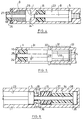
- Fig. 4 shows a partial longitudinal section through another Embodiment. While in the embodiment according to FIG. 1 the piston guide 4 is slidably formed in the housing 1 is in the embodiment of FIG. 4 are one piece Housing 1 with a cylindrical interior formed piston guide 23 shown. For the production the housing 1 would have to be constructed from several parts, what but is not shown for reasons of simplification.
- an inward one Flange 24 is present, which has a passage 25 for the shaft 8 of the driving piston 5.
- the ring element Brake element 16 On the driving piston 5 facing Side of the flange 24 is the ring element Brake element 16 arranged. It can be in the piston guide 23 displaceable both with the driving piston 5 as well the flange 24 attached itself or just be attached. The The braking effect of this ring element 16 then happens simply by contacting the side surface of the flange 24.
- the free end of the Housing 1 also provided with a damping element 26, which corresponds to the damping element 18 of the pin guide 9.
- a flat plate 27 vulcanized from metal, for example.
- Fig. 5 also shows a simplified embodiment, at the driving piston 5 via a sleeve-shaped one, for example Link 28 with a piston-shaped guide cylinder 29 connected is.
- This guide piston 29 contains two diametrically arranged approaches 30, each through a housing slot 31 protrude outwards.
- On the outside of the housing 1 lying areas of the lugs 30 is a spring 32, respectively Example made of elastomeric material, attached to each other end is connected to a housing-fixed extension 33.
- the only indicated spring 32 is in this case as a tension spring educated.
- the distance between the driving piston 5 and the Guide piston 29 is selected so that the drive piston 5 only reached the slot 31 at the end of its movement, so that only then the propellant gas can escape there.
- Fig. 6 shows another embodiment in which the driving piston 5 on the side opposite the piston guide 23 is provided with a rod 34, at the end of which a piston-shaped Guide cylinder 35 is attached.
- the rod 34 reaches through an opening in a transverse wall 36.
- the transverse wall 36 delimits a cavity 37 in which both the braking element 16 and a return spring 38 are housed.
- the Brake element 16 is immediately on in the example shown the transverse wall 38 arranged, while the return spring 38 in the remaining space is attached.
- the guide piston moves to the left 35 with and leads to compression in the same way the return spring 38 and then to concern the Brake element 16, so that this then the drive piston 15 on Also decelerated at the end of his movement.
- the braking element 16 can of course also in the front room according to Fig. 1, i.e. between The front of the piston and the pin guide must be arranged so that only the return spring is in the rear cavity 37 located.
- the embodiment 6 is particularly suitable for a cartridge feed by means of a rotary movement of the housing 1, which is similar due to the axial movement over a control curve as can be achieved with a ballpoint pen mechanism.
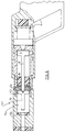
- Fig. 7 shows schematically and in ready to fire (cocked) Condition an embodiment in which, for example, the Arrangement of Fig. 4 can be used.
- the bolt gun contains a two-part housing consisting of a holding part 40 and axially opposite this sliding front housing part 41, which is also the Piston guide 4 according to the previous embodiment Fig. 1 corresponds.
- the front housing part 41 is the Bolt guide 9 arranged and the piston guide 23 formed.
- One between a shoulder 42 of the bracket member and a shoulder 43 of the front part acting compression spring provides ensure that the housing front part 41 when it is not on the Pressed underground, in an extended state located.
- the cartridge abutment is located in the holding part 40 44, on which the cartridge is pressed when pressing the front part of the housing 41 supports.
- the indicated cartridges 45 are pressed into the cartridge bearing 45a at the end of the Front part 41 inserted to be fired there become.
- the cartridge storage 44 is guided by a stamp 46, at its free end a pressure plate 47 is arranged. Between the pressure plate 47 and the end wall 48, the Limited interior space of the bracket 40 is another Damping element 49 arranged.
- the damping element 49 is a relatively hard elastomer material, because when pressing the Front housing part 41 and / or the bolt guide 9 for tensioning of the device, the cartridge abutment 44 does not yield should.
- the damping element 49 serves to dampen the at Recoil and thus relieves the Operator of the device.
- Fig. 8 shows a similar device, now only the Differences are mentioned.
- FIGS. 4 and 7 The existing in the embodiment of FIGS. 4 and 7 after internally directed flange 24 is here as a loose screw-in element 24 ', wherein the front housing part 41 consists of two parts that can be screwed together are constructed.
- the piston skirt 8 extends in the embodiment according to FIG. 8 when pushed back only to about the outside of the Flange 24.
- a second driving piston 51 arranged, the disc-shaped guide collar 52nd having.
- the damping element 53 arranged, the second driving piston 51 on its guide collar 52 brakes. While in the previous embodiments two chronologically and spatially arranged one behind the other Damping occurs, namely the one for braking of the driving piston and on the other hand that of the resulting ones Axial movement of the entire moving system housing and / or bolt guide, are in the embodiment 8 three such attenuations connected in series, the braking of the driving piston 5 and the second drive piston 51 can also occur simultaneously.
- the shaft 8 of the driving piston 5 can with the additional Driving piston 51 by a bayonet lock or a other facility connected.
- FIG. 9 shows different possibilities for a return spring. While with the simplified 3 the return spring as one Neck made of rubber-elastic material was shown 9 as a return spring, a ring 54 made of elastomer material, which is claimed on train. Simply put, is a hook 55 is attached to the housing of the bolt-actuating device, connected to the driving piston 5 during a second hook 56 is. This could happen, for example, as in the Fig. 5 shown. When the driving piston 5 moves forward, 9 to the left, this ring is then subjected to tension.
- the elastomer ring 54 could also be in the rear cavity 37 the embodiment of FIG. 6 may be arranged.
- Fig. 10 shows a spring element 57, which is similar to the 3 around the shaft 8 of the driving piston 5 is arranged around. It is made up of a variety of individual Layers 58 constructed, each made of elastomer material exist and can be loose or connected. For example by gluing or vulcanizing. Through the Variety of loose or interconnected layers better dimensional stability can be achieved. Likewise it is possible that the layers of different material exist and / or the spring elements in conical or are double conical.
- FIGS. 11 and 12. 11 is again only to be understood schematically.
- the element shown in Fig. 11 contains individual disks 59, the same diameter for better guidance like the driving piston 5 and form a kind of chamber. In between are the actual spring elements, the Elastomer rings 60.
- the elastomer rings 60 can also be arranged in shallow depressions, or it 59 small projections could be provided on the surfaces of the disks to be the one when the device is compressed Complete flat pressing (block setting) of the elastomer rings 60 to prevent.
- the cross section round elastomer rings 60 could also rings 61 with other Cross-section and other material.
- This element can be found in the working area in front of the driving piston 5 and behind in the cavity as in the embodiment 6 may be arranged.
- a bolt-driving tool of the design according to the invention can be easily provided with a nail magazine on the front, so that an automatic and quick setting of the Fasteners is guaranteed.
Landscapes
- Engineering & Computer Science (AREA)
- Chemical & Material Sciences (AREA)
- Combustion & Propulsion (AREA)
- Mechanical Engineering (AREA)
- Portable Nailing Machines And Staplers (AREA)
- Braking Arrangements (AREA)
- Details Of Spanners, Wrenches, And Screw Drivers And Accessories (AREA)
- Diaphragms And Bellows (AREA)
- Gripping Jigs, Holding Jigs, And Positioning Jigs (AREA)
- Dowels (AREA)
- Vibration Dampers (AREA)
- Surgical Instruments (AREA)
- Fluid-Damping Devices (AREA)
- Vehicle Body Suspensions (AREA)
- Forging (AREA)
- Braking Systems And Boosters (AREA)
Abstract
Description
- Fig.1
- einen teilweisen Längsschnitt durch ein Bolzensetzgerät nach der Erfindung;
- Fig. 2
- einen der Fig. 1 entsprechenden Längsschnitt durch eine Bolzenführung nach einer zweiten Ausführungsform;
- Fig. 3
- einen Treibkolben mit einer um seinen Schaft herum angeordneten Rückstellfeder;
- Fig. 4
- einen weiteren rein schematischen Schnitt durch den vorderen Teil eines Bolzensetzgeräts nach einer zweiten Ausführungsform;
- Fig. 5
- einen der Fig. 4 entsprechenden ebenfalls vereinfachten Schnitt;
- Fig. 6
- einen weiteren ebenfalls vereinfachten Schnitt durch ein Bolzensetzgerät;
- Fig. 7
- einen schematischen Längsschnitt durch ein Bolzensetzgerät nach einer weiteren Ausführungsform;
- Fig. 8
- einen der Fig. 7 entsprechenden Längsschnitt durch ein weiteres Bolzensetzgerät;
- Fig. 9
- die Ansicht einer mit einem Treibkolben verbundenen Rückstellfeder;
- Fig. 10
- eine weitere Ausführungsform einer mit einem Treibkolben zusammenwirkenden Rückstellfeder;
- Fig. 11
- eine der Fig. 10 entsprechende Darstellung bei einer weiteren Ausführungsform;
- Fig. 12
- eine der Fig. 11 entsprechende Darstellung als Kammerbauweise.
Claims (22)
- Bolzensetzgerät, mit1.1 einem Gehäuse (1),1.2 einem in dem Gehäuse (1) angeordneten Treibkolben (5), der1.2.1 durch eine Treibladung ein Befestigungsmittel (15) setzt,1.3 einer Bolzenführung (9), die1.3.1 das zu setzende Befestigungselement (15) vor und/oder während des Setzvorgangs aufnimmt und mindestens teilweise führt, sowie mit1.4 einer Feder aus elastisch verformbaren Material, insbesondere aus Elastomermaterial, zum Zurückschieben des Treibkolbens (5) nach dem Setzvorgang, wobei ggf. die Feder als Hülse (22) ausgebildet ist, die einen Schaft (8) des Treibkolbens (5) umgibt und insbesondere balgartig ausgebildet ist.
- Bolzensetzgerät nach Anspruch 1, mit einem Bremselement (16) zum Abbremsen des Treibkolbens (5) gegenüber dem Gehäuse (1) am Ende der Schubbewegung des Treibkolbens (5).
- Bolzensetzgerät nach Anspruch 1 oder 2, mit einem Dämpfungselement (18), das elastisch deformierbar und mit der Stirnfläche (10) des Gehäuses und/oder mit der Bolzenführung (9) verbunden ist bzw. einen Teil dieser bildet.
- Bolzensetzgerät nach einem der vorhergehenden Ansprüche, bei dem das Dämpfungselement (18) mit dem vorderen Ende der Bolzenführung (9) verbunden ist und/oder als Ringelement (21) zwischen zwei die Bolzenführung (9) bildenden Ringteilen eingesetzt und mit diesen verbunden ist.
- Bolzensetzgerät nach einem der vorhergehenden Ansprüche, bei dem die Bolzenführung (9), mit der das Dämpfungselement (18) verbunden ist, axial verschiebbar ist.
- Bolzensetzgerät nach einem der vorhergehenden Ansprüche, bei dem das Dämpfungselement (18) sich bei axialer Beaufschlagung radial erweitert.
- Bolzensetzgerät nach einem der vorhergehenden Ansprüche, bei dem das Dämpfungselement (18) aus einem Elastomer gebildet ist.
- Bolzensetzgerät nach einem der vorhergehenden Ansprüche, bei dem das Dämpfungselement (18) anvulkanisiert oder angeklebt ist.
- Bolzensetzgerät nach einem der vorhergehenden Ansprüche, bei dem das Dämpfungselement (18) mit seiner radialen Außenseite einer zylindrischen Wand des Gehäuses (1) gegenüberliegend angeordnet ist, wobei insbesondere die radiale Außenseite des Dämpfungselements (18) von der zylindrischen Wand des Gehäuses (1) einen geringen bis keinen radialen Abstand aufweist.
- Bolzensetzgerät nach einem der vorhergehenden Ansprüche, bei dem die Bolzenführung (9) mindestens teilweise aus Kunstharzpreßholz besteht.
- Bolzensetzgerät nach einem der vorhergehenden Ansprüche, bei dem das freie Ende des mit der Bolzenführung (9) verbundenen Dämpfungselements (18) einen dünnen Ring (27) aus nicht expandierendem Material aufweist.
- Bolzensetzgerät nach einem der vorhergehenden Ansprüche, bei dem ein Gehäuse (1) mit einer Kolbenführung (23) einen nach innen gerichteten Flansch (24) zur Anlage des Bremselements (16) aufweist.
- Bolzensetzgerät nach einem der vorhergehenden Ansprüche, bei dem das Gehäuse aus einem einen Handgriff (2) aufweisenden Halterungsteil (40) und einem die Kolbenführung (23), den Kolben (5) und die Bolzenführung (9) aufweisenden zweiten Gehäuseteil (41) aufgebaut ist, der gegenüber dem Halterungsteil (40) axial bewegbar gehaltert ist, wobei zwischen den beiden Teilen (40, 41) ein Rückstoßdämpfungselement (49) vorgesehen ist.
- Bolzensetzgerät nach einem der vorhergehenden Ansprüche, bei dem die Feder im Raum zwischen der Bolzenführung (9) und dem Treibkolben (5) angeordnet ist und/oder bei dem der Treibkolben (5) eine rückwärtige Verlängerung aufweist, an der die Feder angreift.
- Bolzensetzgerät nach einem der vorhergehenden Ansprüche, bei dem die Feder als Druckfeder ausgebildet ist.
- Bolzensetzgerät nach einem der vorhergehenden Ansprüche, bei dem der Kolben (5) seitliche durch Schlitze (31) in dem Gehäuse (1) hindurchgreifende Ansätze (30) aufweist, an denen die gegebenenfalls als Zugfedern ausgebildeten Federn (32) angreifen.
- Bolzensetzgerät nach einem der vorhergehenden Ansprüche, bei dem die Zugfeder (32) als Elastomerring (54) ausgebildet ist.
- Bolzensetzgerät nach einem der vorhergehenden Ansprüche, bei dem die Feder (57) aus losen oder miteinander verbundenen Schichten (58) aufgebaut ist, die ggf. aus verschiedenen Materialien bestehen, insbesondere abwechselnd aus härterem und weicherem Material, wobei vorzugsweise das härtere Material (59) das Bremselement (16) für den Treibkolben (5) und das weichere Material (60, 61) die Rückstellfeder bildet.
- Bolzensetzgerät nach Anspruch 18, bei dem die harten Schichten (59) als Scheiben mit kleinen Ansätzen ausgebildet sind, die beim Zusammendrücken eine Kammer für die weichen Elastomerringe bilden.
- Bolzensetzgerät nach Anspruch 18 oder 19, bei dem die harten Scheiben (59) beim Zusammendrücken einen massiven Block bilden und die vom Schubkolben (5) aufgebrachte Energie auf ein vorgelagertes Bremselement (16) übertragen.
- Bolzensetzgerät nach einem der vorhergehenden Ansprüche, bei dem die Rückstellfeder (57) und das Bremselement (16) als eine Baueinheit ausgeführt sind.
- Bolzensetzgerät nach einem der vorhergehenden Ansprüche, bei dem an der Vorderseite des Gehäuses (1) ein Nagelmagazin angebracht ist, das an seiner Andrückfläche mit einen Dämpfungselement (18) verbunden ist.
Applications Claiming Priority (3)
| Application Number | Priority Date | Filing Date | Title |
|---|---|---|---|
| DE19509763A DE19509763A1 (de) | 1995-03-17 | 1995-03-17 | Bolzensetzgerät |
| DE19509763 | 1995-03-17 | ||
| EP96103717A EP0732178B1 (de) | 1995-03-17 | 1996-03-09 | Bolzensetzgerät |
Related Parent Applications (2)
| Application Number | Title | Priority Date | Filing Date |
|---|---|---|---|
| EP96103717.3 Division | 1996-03-09 | ||
| EP96103717A Division EP0732178B1 (de) | 1995-03-17 | 1996-03-09 | Bolzensetzgerät |
Publications (3)
| Publication Number | Publication Date |
|---|---|
| EP0995552A2 true EP0995552A2 (de) | 2000-04-26 |
| EP0995552A3 EP0995552A3 (de) | 2000-11-08 |
| EP0995552B1 EP0995552B1 (de) | 2007-05-02 |
Family
ID=7756986
Family Applications (2)
| Application Number | Title | Priority Date | Filing Date |
|---|---|---|---|
| EP99124281A Expired - Lifetime EP0995552B1 (de) | 1995-03-17 | 1996-03-09 | Bolzensetzgerät |
| EP96103717A Expired - Lifetime EP0732178B1 (de) | 1995-03-17 | 1996-03-09 | Bolzensetzgerät |
Family Applications After (1)
| Application Number | Title | Priority Date | Filing Date |
|---|---|---|---|
| EP96103717A Expired - Lifetime EP0732178B1 (de) | 1995-03-17 | 1996-03-09 | Bolzensetzgerät |
Country Status (7)
| Country | Link |
|---|---|
| EP (2) | EP0995552B1 (de) |
| AT (2) | ATE361179T1 (de) |
| DE (3) | DE19509763A1 (de) |
| DK (1) | DK0732178T3 (de) |
| ES (2) | ES2284233T3 (de) |
| GR (1) | GR3033960T3 (de) |
| PT (1) | PT732178E (de) |
Families Citing this family (14)
| Publication number | Priority date | Publication date | Assignee | Title |
|---|---|---|---|---|
| DE19635312A1 (de) * | 1996-09-02 | 1998-03-05 | Hilti Ag | Setzgerät |
| DE19638341A1 (de) * | 1996-09-19 | 1998-03-26 | Adolf Wuerth Gmbh & Co Kg | Bolzenschubgerät und Feder dafür |
| DE19648535B4 (de) * | 1996-11-24 | 2006-05-11 | Gerd Dr.-Ing. Kellner | Vorrichtung zum Setzen von Bolzen |
| DE19722795A1 (de) * | 1997-05-30 | 1998-12-03 | Hilti Ag | Setzgerät |
| DE19800847A1 (de) * | 1997-12-04 | 1999-06-17 | Gerd Dr Ing Kellner | Gerät zum Setzen eines Befestigungselementes in einen Setzuntergrund und Verwendung des Gerätes |
| DE19755730A1 (de) * | 1997-12-15 | 1999-06-17 | Hilti Ag | Bolzensetzgerät |
| PL185374B1 (pl) * | 1998-01-19 | 2003-04-30 | Lagodzinska Boguslawa | Samorepetujący osadzak wybuchowy |
| RU2224071C2 (ru) * | 1998-04-14 | 2004-02-20 | АДОЛЬФ ВЮРТ ГмбХ унд Ко. КГ | Строительно-монтажный пистолет и пружина для него |
| DE19824389A1 (de) * | 1998-05-30 | 1999-12-02 | Adolf Wuerth Gmbh & Co Kg | Bolzenschubgerät |
| DE10251307B4 (de) * | 2002-11-04 | 2014-04-10 | Hilti Aktiengesellschaft | Brennkraftbetriebenes Setzgerät |
| DE10358576A1 (de) * | 2003-12-15 | 2005-07-28 | Hilti Ag | Brennkraftbetriebenes Setzgerät |
| DE102008000909A1 (de) | 2008-04-01 | 2009-10-08 | Hilti Aktiengesellschaft | Brennkraftbetriebenes Setzgerät |
| GB0810678D0 (en) * | 2008-06-11 | 2008-07-16 | Black & Decker Inc | Resilient stop assembly for impact tool |
| WO2023135041A1 (de) * | 2022-01-14 | 2023-07-20 | Fischerwerke Gmbh & Co. Kg | Bolzensetzgerät zum eintreiben eines befestigungselements in einen untergrund |
Family Cites Families (20)
| Publication number | Priority date | Publication date | Assignee | Title |
|---|---|---|---|---|
| US3126630A (en) * | 1964-03-31 | T catlin | ||
| US2354958A (en) * | 1943-05-29 | 1944-08-01 | Hydraulic Brake Co | Diaphragm pump |
| CH318934A (de) * | 1952-12-29 | 1957-01-31 | Anstalt Fuer Montage Technik | Schiessvorrichtung für Verankerungsbolzen |
| DE1478819A1 (de) * | 1963-09-04 | 1969-07-17 | Herbert Behrend | Geraet zum Einstanzen von Bolzen od.dgl. |
| US3301335A (en) * | 1964-04-20 | 1967-01-31 | Thomas E Snelling | Energy absorbing structure |
| US3331546A (en) * | 1965-06-01 | 1967-07-18 | Olin Mathieson | Piston return and buffer system |
| DE1603852C3 (de) * | 1968-01-29 | 1975-12-04 | Hilti Ag, Schaan (Liechtenstein) | Abfangvorrichtung für den Eintreibkolben eines pulverkraftbetriebenen Bolzensetzgerätes |
| FR1600417A (de) * | 1968-08-05 | 1970-07-27 | ||
| FR2109090A5 (de) * | 1970-09-16 | 1972-05-26 | Reymond Michel | |
| US4204622A (en) * | 1975-05-23 | 1980-05-27 | Cunningham James D | Electric impact tool |
| DE7622745U1 (de) * | 1976-07-19 | 1978-04-27 | Hilti Ag, Schaan (Liechtenstein) | Pulverkraftbetriebenes bolzensetzgeraet mit einer abfangvorrichtung fuer den treibkolben |
| DE2727639A1 (de) * | 1977-06-20 | 1979-01-04 | Hilti Ag | Pulverkraftbetriebenes bolzensetzgeraet |
| DE2850273A1 (de) * | 1978-11-20 | 1980-05-29 | Hilti Ag | Pulverkraftbetriebenes bolzensetzgeraet |
| US4442757A (en) * | 1981-08-24 | 1984-04-17 | Baker Cac, Inc. | Fluid pressure actuator having bias element immersed in non-corrosive environment |
| AU548929B2 (en) * | 1982-07-27 | 1986-01-09 | Gareth J. Smith | Dimpling fastener driving tool |
| FR2608493B1 (fr) * | 1986-12-23 | 1994-09-02 | Prospection & Inventions | Appareil de scellement a tir indirect |
| DE3702364A1 (de) * | 1987-01-28 | 1988-08-04 | Mo N Proizv Ob Mekh | Handwerkzeug zum einschlagen von befestigungselementen |
| DE8915510U1 (de) * | 1989-03-22 | 1990-08-30 | Kellner, Gerd, Dr.-Ing., 7230 Schramberg | Bolzensetzgerät |
| DE3924620A1 (de) * | 1989-07-26 | 1991-01-31 | Hilti Ag | Pulverkraftbetriebenes bolzensetzgeraet |
| US5205457A (en) * | 1992-01-06 | 1993-04-27 | Blomquist Jr Roy A | Driving tool and method |
-
1995
- 1995-03-17 DE DE19509763A patent/DE19509763A1/de not_active Withdrawn
-
1996
- 1996-03-09 EP EP99124281A patent/EP0995552B1/de not_active Expired - Lifetime
- 1996-03-09 DK DK96103717T patent/DK0732178T3/da active
- 1996-03-09 AT AT99124281T patent/ATE361179T1/de not_active IP Right Cessation
- 1996-03-09 DE DE59611428T patent/DE59611428D1/de not_active Expired - Lifetime
- 1996-03-09 ES ES99124281T patent/ES2284233T3/es not_active Expired - Lifetime
- 1996-03-09 DE DE59605376T patent/DE59605376D1/de not_active Expired - Lifetime
- 1996-03-09 ES ES96103717T patent/ES2149396T3/es not_active Expired - Lifetime
- 1996-03-09 AT AT96103717T patent/ATE193668T1/de not_active IP Right Cessation
- 1996-03-09 EP EP96103717A patent/EP0732178B1/de not_active Expired - Lifetime
- 1996-03-09 PT PT96103717T patent/PT732178E/pt unknown
-
2000
- 2000-07-17 GR GR20000401645T patent/GR3033960T3/el not_active IP Right Cessation
Also Published As
| Publication number | Publication date |
|---|---|
| ATE193668T1 (de) | 2000-06-15 |
| DE19509763A1 (de) | 1996-09-19 |
| GR3033960T3 (en) | 2000-11-30 |
| ES2149396T3 (es) | 2000-11-01 |
| PT732178E (pt) | 2000-09-29 |
| DK0732178T3 (da) | 2000-10-30 |
| ATE361179T1 (de) | 2007-05-15 |
| EP0732178A1 (de) | 1996-09-18 |
| ES2284233T3 (es) | 2007-11-01 |
| DE59605376D1 (de) | 2000-07-13 |
| EP0732178B1 (de) | 2000-06-07 |
| EP0995552A3 (de) | 2000-11-08 |
| DE59611428D1 (de) | 2007-06-14 |
| EP0995552B1 (de) | 2007-05-02 |
Similar Documents
| Publication | Publication Date | Title |
|---|---|---|
| DE3119956C2 (de) | Schallgedämpftes Eintreibgerät für Befestigungsmittel | |
| EP0732178B1 (de) | Bolzensetzgerät | |
| EP1035950B1 (de) | Gerät zum setzen eines befestigungselementes in einen setzuntergrund und verwendung des gerätes | |
| DE1603918C3 (de) | Treibkolbenpuffer und TreibkolbenrückfUhrfeder an einem Eintreibwerkzeug | |
| DE3515244C2 (de) | ||
| DE19755730A1 (de) | Bolzensetzgerät | |
| DE1478822A1 (de) | Bolzensetzgeraet | |
| DE2720186A1 (de) | Durch eine explosivladung betaetigtes schlagkolbengeraet | |
| DE19947464A1 (de) | Bolzensetzgerät zum Eintreiben von Bolzen oder dergleichen in Bauteile | |
| EP0805003B1 (de) | Pulverkraftbetriebenes Bolzensetzgerät | |
| DE3930592A1 (de) | Bolzensetzgeraet | |
| DE10259817A1 (de) | Brennkraftbetriebenes Setzgerät für Befestigungselemente | |
| DE10105881B4 (de) | Kolbenhalterung | |
| DE102005000106B4 (de) | Setzgerät | |
| DE102012217686A1 (de) | Geradezug-Repetiergewehr mit einem Verschlussmechanismus | |
| EP0962289B1 (de) | Bolzenschubgerät | |
| DE2927507C2 (de) | Bolzenschußapparat | |
| DE2743155A1 (de) | Schlaghammer | |
| DE3739448A1 (de) | Automatische feuerwaffe | |
| WO1999059779A1 (de) | Vorrichtung zur erzeugung einer schlagartigen vorschubbewegung | |
| DE2954538C2 (de) | Bolzenschußapparat zur Betäubung von Schlachtvieh | |
| DE1478838C3 (de) | Abfangeinrichtung für den Flugkolben eines Brennkraftbolzensetzers | |
| DE1703439C3 (de) | Pulverkraftbetriebenes Bolzensetzgerät | |
| DE894530C (de) | Presslufthammer mit Einrichtung zur Stossdaempfung | |
| DE2226598C3 (de) | Pulverkraftbetriebenes Werkzeug |
Legal Events
| Date | Code | Title | Description |
|---|---|---|---|
| PUAI | Public reference made under article 153(3) epc to a published international application that has entered the european phase |
Free format text: ORIGINAL CODE: 0009012 |
|
| AC | Divisional application: reference to earlier application |
Ref document number: 732178 Country of ref document: EP |
|
| AK | Designated contracting states |
Kind code of ref document: A2 Designated state(s): AT BE CH DE DK ES FI FR GB GR IE IT LI LU MC NL PT SE |
|
| PUAL | Search report despatched |
Free format text: ORIGINAL CODE: 0009013 |
|
| AK | Designated contracting states |
Kind code of ref document: A3 Designated state(s): AT BE CH DE DK ES FI FR GB GR IE IT LI LU MC NL PT SE |
|
| 17P | Request for examination filed |
Effective date: 20010130 |
|
| AKX | Designation fees paid |
Free format text: AT BE CH DE DK ES FI FR GB GR IE IT LI LU MC NL PT SE |
|
| 17Q | First examination report despatched |
Effective date: 20050623 |
|
| GRAP | Despatch of communication of intention to grant a patent |
Free format text: ORIGINAL CODE: EPIDOSNIGR1 |
|
| GRAS | Grant fee paid |
Free format text: ORIGINAL CODE: EPIDOSNIGR3 |
|
| GRAA | (expected) grant |
Free format text: ORIGINAL CODE: 0009210 |
|
| AC | Divisional application: reference to earlier application |
Ref document number: 0732178 Country of ref document: EP Kind code of ref document: P |
|
| AK | Designated contracting states |
Kind code of ref document: B1 Designated state(s): AT BE CH DE DK ES FI FR GB GR IE IT LI LU MC NL PT SE |
|
| PG25 | Lapsed in a contracting state [announced via postgrant information from national office to epo] |
Ref country code: FI Free format text: LAPSE BECAUSE OF FAILURE TO SUBMIT A TRANSLATION OF THE DESCRIPTION OR TO PAY THE FEE WITHIN THE PRESCRIBED TIME-LIMIT Effective date: 20070502 |
|
| REG | Reference to a national code |
Ref country code: GB Ref legal event code: FG4D Free format text: NOT ENGLISH |
|
| REG | Reference to a national code |
Ref country code: CH Ref legal event code: EP |
|
| REG | Reference to a national code |
Ref country code: IE Ref legal event code: FG4D Free format text: LANGUAGE OF EP DOCUMENT: GERMAN |
|
| REF | Corresponds to: |
Ref document number: 59611428 Country of ref document: DE Date of ref document: 20070614 Kind code of ref document: P |
|
| REG | Reference to a national code |
Ref country code: SE Ref legal event code: TRGR |
|
| NLV1 | Nl: lapsed or annulled due to failure to fulfill the requirements of art. 29p and 29m of the patents act | ||
| REG | Reference to a national code |
Ref country code: ES Ref legal event code: FG2A Ref document number: 2284233 Country of ref document: ES Kind code of ref document: T3 |
|
| GBV | Gb: ep patent (uk) treated as always having been void in accordance with gb section 77(7)/1977 [no translation filed] |
Effective date: 20070502 |
|
| REG | Reference to a national code |
Ref country code: IE Ref legal event code: FD4D |
|
| PG25 | Lapsed in a contracting state [announced via postgrant information from national office to epo] |
Ref country code: PT Free format text: LAPSE BECAUSE OF FAILURE TO SUBMIT A TRANSLATION OF THE DESCRIPTION OR TO PAY THE FEE WITHIN THE PRESCRIBED TIME-LIMIT Effective date: 20071002 Ref country code: NL Free format text: LAPSE BECAUSE OF FAILURE TO SUBMIT A TRANSLATION OF THE DESCRIPTION OR TO PAY THE FEE WITHIN THE PRESCRIBED TIME-LIMIT Effective date: 20070502 Ref country code: IE Free format text: LAPSE BECAUSE OF FAILURE TO SUBMIT A TRANSLATION OF THE DESCRIPTION OR TO PAY THE FEE WITHIN THE PRESCRIBED TIME-LIMIT Effective date: 20070502 Ref country code: DK Free format text: LAPSE BECAUSE OF FAILURE TO SUBMIT A TRANSLATION OF THE DESCRIPTION OR TO PAY THE FEE WITHIN THE PRESCRIBED TIME-LIMIT Effective date: 20070502 |
|
| PLBE | No opposition filed within time limit |
Free format text: ORIGINAL CODE: 0009261 |
|
| STAA | Information on the status of an ep patent application or granted ep patent |
Free format text: STATUS: NO OPPOSITION FILED WITHIN TIME LIMIT |
|
| 26N | No opposition filed |
Effective date: 20080205 |
|
| PG25 | Lapsed in a contracting state [announced via postgrant information from national office to epo] |
Ref country code: GR Free format text: LAPSE BECAUSE OF FAILURE TO SUBMIT A TRANSLATION OF THE DESCRIPTION OR TO PAY THE FEE WITHIN THE PRESCRIBED TIME-LIMIT Effective date: 20070803 Ref country code: GB Free format text: LAPSE BECAUSE OF FAILURE TO SUBMIT A TRANSLATION OF THE DESCRIPTION OR TO PAY THE FEE WITHIN THE PRESCRIBED TIME-LIMIT Effective date: 20070502 |
|
| BERE | Be: lapsed |
Owner name: ADOLF WURTH G.M.B.H. & CO. KG Effective date: 20080331 |
|
| PG25 | Lapsed in a contracting state [announced via postgrant information from national office to epo] |
Ref country code: MC Free format text: LAPSE BECAUSE OF NON-PAYMENT OF DUE FEES Effective date: 20080331 |
|
| REG | Reference to a national code |
Ref country code: CH Ref legal event code: PL |
|
| PG25 | Lapsed in a contracting state [announced via postgrant information from national office to epo] |
Ref country code: LI Free format text: LAPSE BECAUSE OF NON-PAYMENT OF DUE FEES Effective date: 20080331 Ref country code: CH Free format text: LAPSE BECAUSE OF NON-PAYMENT OF DUE FEES Effective date: 20080331 |
|
| PG25 | Lapsed in a contracting state [announced via postgrant information from national office to epo] |
Ref country code: BE Free format text: LAPSE BECAUSE OF NON-PAYMENT OF DUE FEES Effective date: 20080331 |
|
| PG25 | Lapsed in a contracting state [announced via postgrant information from national office to epo] |
Ref country code: AT Free format text: LAPSE BECAUSE OF NON-PAYMENT OF DUE FEES Effective date: 20080309 |
|
| PGFP | Annual fee paid to national office [announced via postgrant information from national office to epo] |
Ref country code: SE Payment date: 20090325 Year of fee payment: 14 |
|
| PGFP | Annual fee paid to national office [announced via postgrant information from national office to epo] |
Ref country code: FR Payment date: 20090318 Year of fee payment: 14 |
|
| PGFP | Annual fee paid to national office [announced via postgrant information from national office to epo] |
Ref country code: ES Payment date: 20100326 Year of fee payment: 15 |
|
| PG25 | Lapsed in a contracting state [announced via postgrant information from national office to epo] |
Ref country code: LU Free format text: LAPSE BECAUSE OF NON-PAYMENT OF DUE FEES Effective date: 20080309 |
|
| PGFP | Annual fee paid to national office [announced via postgrant information from national office to epo] |
Ref country code: IT Payment date: 20100326 Year of fee payment: 15 |
|
| EUG | Se: european patent has lapsed | ||
| REG | Reference to a national code |
Ref country code: FR Ref legal event code: ST Effective date: 20101130 |
|
| PG25 | Lapsed in a contracting state [announced via postgrant information from national office to epo] |
Ref country code: FR Free format text: LAPSE BECAUSE OF NON-PAYMENT OF DUE FEES Effective date: 20100331 |
|
| PG25 | Lapsed in a contracting state [announced via postgrant information from national office to epo] |
Ref country code: IT Free format text: LAPSE BECAUSE OF NON-PAYMENT OF DUE FEES Effective date: 20110309 |
|
| REG | Reference to a national code |
Ref country code: ES Ref legal event code: FD2A Effective date: 20120424 |
|
| PG25 | Lapsed in a contracting state [announced via postgrant information from national office to epo] |
Ref country code: ES Free format text: LAPSE BECAUSE OF NON-PAYMENT OF DUE FEES Effective date: 20110310 |
|
| PG25 | Lapsed in a contracting state [announced via postgrant information from national office to epo] |
Ref country code: SE Free format text: LAPSE BECAUSE OF NON-PAYMENT OF DUE FEES Effective date: 20100310 |
|
| PGFP | Annual fee paid to national office [announced via postgrant information from national office to epo] |
Ref country code: DE Payment date: 20140319 Year of fee payment: 19 |
|
| REG | Reference to a national code |
Ref country code: DE Ref legal event code: R119 Ref document number: 59611428 Country of ref document: DE |
|
| PG25 | Lapsed in a contracting state [announced via postgrant information from national office to epo] |
Ref country code: DE Free format text: LAPSE BECAUSE OF NON-PAYMENT OF DUE FEES Effective date: 20151001 |