EP0995572A1 - Dispositif de dosage et transport pour des composants de matière plastique - Google Patents
Dispositif de dosage et transport pour des composants de matière plastique Download PDFInfo
- Publication number
- EP0995572A1 EP0995572A1 EP99120490A EP99120490A EP0995572A1 EP 0995572 A1 EP0995572 A1 EP 0995572A1 EP 99120490 A EP99120490 A EP 99120490A EP 99120490 A EP99120490 A EP 99120490A EP 0995572 A1 EP0995572 A1 EP 0995572A1
- Authority
- EP
- European Patent Office
- Prior art keywords
- dosing
- conveying device
- mixer
- injection molding
- conveying
- Prior art date
- Legal status (The legal status is an assumption and is not a legal conclusion. Google has not performed a legal analysis and makes no representation as to the accuracy of the status listed.)
- Granted
Links
- 239000004033 plastic Substances 0.000 title claims abstract description 25
- 229920003023 plastic Polymers 0.000 title claims abstract description 25
- 238000001746 injection moulding Methods 0.000 claims description 36
- 239000000654 additive Substances 0.000 claims description 9
- 239000000203 mixture Substances 0.000 claims description 6
- 230000001105 regulatory effect Effects 0.000 claims description 2
- 239000000463 material Substances 0.000 abstract description 10
- 238000002347 injection Methods 0.000 abstract description 6
- 239000007924 injection Substances 0.000 abstract description 6
- 238000004904 shortening Methods 0.000 description 2
- 229920002379 silicone rubber Polymers 0.000 description 2
- 239000004944 Liquid Silicone Rubber Substances 0.000 description 1
- 238000006243 chemical reaction Methods 0.000 description 1
- 238000010276 construction Methods 0.000 description 1
- 230000003111 delayed effect Effects 0.000 description 1
- 230000007257 malfunction Effects 0.000 description 1
- 238000000034 method Methods 0.000 description 1
- 230000006855 networking Effects 0.000 description 1
- 239000004848 polyfunctional curative Substances 0.000 description 1
- 230000035484 reaction time Effects 0.000 description 1
- 230000003068 static effect Effects 0.000 description 1
- 239000000126 substance Substances 0.000 description 1
- 238000011144 upstream manufacturing Methods 0.000 description 1
Images



Classifications
-
- B—PERFORMING OPERATIONS; TRANSPORTING
- B29—WORKING OF PLASTICS; WORKING OF SUBSTANCES IN A PLASTIC STATE IN GENERAL
- B29C—SHAPING OR JOINING OF PLASTICS; SHAPING OF MATERIAL IN A PLASTIC STATE, NOT OTHERWISE PROVIDED FOR; AFTER-TREATMENT OF THE SHAPED PRODUCTS, e.g. REPAIRING
- B29C45/00—Injection moulding, i.e. forcing the required volume of moulding material through a nozzle into a closed mould; Apparatus therefor
- B29C45/17—Component parts, details or accessories; Auxiliary operations
- B29C45/18—Feeding the material into the injection moulding apparatus, i.e. feeding the non-plastified material into the injection unit
- B29C45/1866—Feeding multiple materials
-
- B—PERFORMING OPERATIONS; TRANSPORTING
- B29—WORKING OF PLASTICS; WORKING OF SUBSTANCES IN A PLASTIC STATE IN GENERAL
- B29B—PREPARATION OR PRETREATMENT OF THE MATERIAL TO BE SHAPED; MAKING GRANULES OR PREFORMS; RECOVERY OF PLASTICS OR OTHER CONSTITUENTS OF WASTE MATERIAL CONTAINING PLASTICS
- B29B7/00—Mixing; Kneading
- B29B7/30—Mixing; Kneading continuous, with mechanical mixing or kneading devices
- B29B7/58—Component parts, details or accessories; Auxiliary operations
- B29B7/60—Component parts, details or accessories; Auxiliary operations for feeding, e.g. end guides for the incoming material
-
- B—PERFORMING OPERATIONS; TRANSPORTING
- B29—WORKING OF PLASTICS; WORKING OF SUBSTANCES IN A PLASTIC STATE IN GENERAL
- B29C—SHAPING OR JOINING OF PLASTICS; SHAPING OF MATERIAL IN A PLASTIC STATE, NOT OTHERWISE PROVIDED FOR; AFTER-TREATMENT OF THE SHAPED PRODUCTS, e.g. REPAIRING
- B29C45/00—Injection moulding, i.e. forcing the required volume of moulding material through a nozzle into a closed mould; Apparatus therefor
- B29C45/17—Component parts, details or accessories; Auxiliary operations
- B29C45/18—Feeding the material into the injection moulding apparatus, i.e. feeding the non-plastified material into the injection unit
- B29C45/1816—Feeding auxiliary material, e.g. colouring material
-
- B—PERFORMING OPERATIONS; TRANSPORTING
- B29—WORKING OF PLASTICS; WORKING OF SUBSTANCES IN A PLASTIC STATE IN GENERAL
- B29K—INDEXING SCHEME ASSOCIATED WITH SUBCLASSES B29B, B29C OR B29D, RELATING TO MOULDING MATERIALS OR TO MATERIALS FOR MOULDS, REINFORCEMENTS, FILLERS OR PREFORMED PARTS, e.g. INSERTS
- B29K2083/00—Use of polymers having silicon, with or without sulfur, nitrogen, oxygen, or carbon only, in the main chain, as moulding material
- B29K2083/005—LSR, i.e. liquid silicone rubbers, or derivatives thereof
Definitions
- the invention relates to a metering and conveying device for plastic components according to the preamble of claim 1.
- Such a metering and conveying device is, for example, from AT 403 135 B. known and is used there in connection with an injection molding machine.
- Gear pumps are the various components of a liquid silicone rubber fed to a mixer and by this mixer, which, like the rest of the whole Dosing and conveying device arranged away from the injection molding machine is fed via flexible lines to the injection molding unit of the injection molding machine.
- lines 14-41 proposed in which the two gear pumps for the two components electronically operated in a regulated manner.
- An extruder is known from DE 196 53 O99 A1, which has two different plastic components be fed.
- the plastic components are via conveyor lines fed to a mixer, which is also the funding.
- the injection molding unit is thus both a metering and conveying device.
- the material is pressed through the movement of a drive shaft through mixing elements and then injected directly into the mold.
- Interchangeable containers for holding the plastic components are not provided. Instead, be upstream Conveying elements in the form of plasticizing extruders the two together melted plastic components to be processed. It is not that possible, such plastic components via a standard unchanged injection molding unit to be injected with a screw conveyor. Because the mixing is not is decoupled from funding, there is no problem that a connection between Dosing and conveying device and injection molding unit must be created.
- the object of the present invention to create a dosing and conveying device that is largely can do without flexible lines, especially after the mixer.
- This task is performed by a dosing and conveying device with the features of Claim 1 solved.
- the metering and conveying device is arranged on the injection molding unit, so that this results in a shortening of any lines that may still be required.
- the mixer itself stands with the feed channel for feeding the material in the injection molding unit in a fixed connection.
- This can preferably be used on flexible lines be dispensed with in this extremely endangered area.
- Weak areas are often the flexible lines and thus the supply lines from the dosing and conveying device to the injection molding unit. This weak area is due to the arrangement made and the possible waiver of flexible Lines removed, which contributes to the safety of the entire machine.
- the mixture is therefore deliberately conveyed from the mixer to the actual funding, so the material does not come from a separate mixer to the injection molding unit and must be handed over to the funding there, at least if you don't our own special injection molding unit with appropriate mixing elements in the area of the funding.
- the state of the art suggests to provide a separate mixing plant and the material via flexible lines feed, not only are the lengths of the delivery lines reduced and fixed connections created, it can also be a conventional injection molding unit without previous conversions are used to process such mixtures.
- the compact dosing and conveying device can be moved as required to e.g. in Connection with injection molding units working vertically in the parting plane to find. It can be tested for functionality at the manufacturer's factory, so that it can be put into operation by the customer without any problems, even when the customer is in remote areas of the world.
- the possibility is created of the conveyor motors to operate under pressure control. Because there are no flexible cables can, this pressure control is more precise than the volume control previously carried out, so that a constant quality of the supplied plastic components is guaranteed. In addition, the pressure control is cheaper to implement than the quantity control used up to now.
- Fig. 1 shows an injection molding machine for processing plastics
- the present Case for processing plastic components to be mixed is used. It is e.g. liquid silicone rubbers, their components can be fed separately to a mixer 63. After mixing, remains a certain reaction time, the pot life, within which the components are processed Need to become. The curing of these components is usually delayed by that e.g. when conveying into the mold cavity one not shown in the drawing Injection mold are cooled while heated in the injection mold so that it hardens.
- the dosing system D shown in Fig. 1 is supported on a support block 74 of the injection molding unit S.
- the injection molding unit S transfers the plastic component mixture with a conveyor 68 into the Mold cavity of the injection mold, which is accommodated in the mold clamping unit F.
- Injection molding unit S and mold clamping unit F are in the exemplary embodiment on a machine base 10.
- the plasticizing cylinder is controlled by a temperature control 70 and a temperature control circuit 69 73 of the injection molding unit S tempered. There is also a in the injection molding machine Integrated vacuum control and an additional temperature control unit 71 can be connected become.
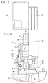
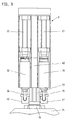
- FIG. 3 a view of the dosing system D in FIG. 1 from the right, are two - there may be more - containers 31, 32 for holding two components shown. These containers are interchangeable cartridges. These cartridges are used by piston-cylinder units 21, 22 among those for Convey necessary delivery pressure set. As a result of this delivery pressure, the Plastic components separated from each other in delivery lines 35.51 and 36.52. They are conveyed from the respective container 31, 32 to a mixer 63, which is the best can be seen in Fig. 4. The mixture of plastic components is conveyed through another delivery line from mixer 63 to injection molding unit S.
- the metering and conveying device is arranged on the injection molding unit S according to FIG. 1. More precisely, it is located on a connection element 75 of the carrier block 74, with which in turn the injection molding unit S on the machine stand 10 supports. The support takes place via a support element 77.
- the mixer 63 is in the form of a further delivery line Feed channel 66 preferably in a fixed connection, e.g. Pipelines, in contrast to a flexible connection.
- a fixed connection e.g. Pipelines
- the cable length is shortened.
- Disorders are here by means of e.g. fixed pipe connections easier to control.
- a pressure sensor 64 is provided on the mixer 63.
- the pressure sensor measures Actual pressure values within the mixing tube and gives them for pressure control of the conveyor motors 45.46 further.
- the conveyor motors 45, 46 are designed as servomotors, so that there is an exact dosage and thus continuous feeding constant quality of the plastic component mixture can be realized.
- the gear pumps 41, 42 are driven by the conveyor motors 45, 46 via gears 45 ', 46' driven.
- the two components come from the gear pumps 41, 42, still in separate delivery lines, to the mixer 63, whereby between the mixer and delivery lines check valves 55,56 are provided which have a backflow prevent mixed material into the delivery lines 51, 52.
- the conveyor lines 51.52 are already dosing sections, since here one according to the requirements of the regulation dosed volume in the delivery lines.
- the static mixer 63 the components are mixed, which via the feed channel 66 to the plasticizing cylinder 67 with the conveying means 68 located therein. From here the material is injected through the nozzle 76 into the mold cavity of the injection mold.
- Dosing device 60 is provided for the addition of additives. These additives can be supplied from a container 62 via line 61. Additives can e.g. Color additives or chemical additives such as hardeners, accelerators or retarders or Additives to modify the material properties.
- the figures show the entire metering and conveying device as a compact construction Unit.
- This unit can be easily mounted on the injection molding machine if required become. It can be used in any way, e.g. also in connection with one in the parting plane injecting injection molding unit.
- the compact dosing and conveying device can be prefabricated in the manufacturer 's company and checked for functionality, so that it only has to be attached to the machine's support body at the customer. The footprint of the machine is not enlarged and the device can be used with the existing machine control on the injection molding machine.
- the delivery lines 35, 36, 51, 52 also being designed as fixed lines can, although they are flexible in the embodiment.
- Conveyor motors 45, 46 with their gears 45 ', 46' and the pressure-controlled gear pumps 41,42 vertically along the motor axis a-a or b-b.
- the mixing tube 63a is essentially parallel to these motor axes of the conveyor motors 45, 46.
- the Piston-cylinder units 21, 22 are essentially parallel to these engine axes a-a, b-b.
- the result is a slim, upward-looking unit, with the Space above the conveyor motors 45, 46 is also used for the control cabinet 20.
- the cylinder of the piston-cylinder units can be used as a supporting part for this control cabinet 20 21.22 serve.
- the components of the dosing and conveying device are located essentially within the vertical projection of the at the top of the facility arranged control cabinet 20 and the piston-cylinder units 21,22.
- this container is located in the space between the two containers 31, 32 and the conveyor motors 45, 46.
Landscapes
- Engineering & Computer Science (AREA)
- Mechanical Engineering (AREA)
- Manufacturing & Machinery (AREA)
- Injection Moulding Of Plastics Or The Like (AREA)
- Processing And Handling Of Plastics And Other Materials For Molding In General (AREA)
- Coating Apparatus (AREA)
Applications Claiming Priority (2)
| Application Number | Priority Date | Filing Date | Title |
|---|---|---|---|
| DE19848060A DE19848060C2 (de) | 1998-10-19 | 1998-10-19 | Dosier- und Fördereinrichtung für Kunststoffkomponenten |
| DE19848060 | 1998-10-19 |
Publications (2)
| Publication Number | Publication Date |
|---|---|
| EP0995572A1 true EP0995572A1 (fr) | 2000-04-26 |
| EP0995572B1 EP0995572B1 (fr) | 2002-06-12 |
Family
ID=7884895
Family Applications (1)
| Application Number | Title | Priority Date | Filing Date |
|---|---|---|---|
| EP99120490A Expired - Lifetime EP0995572B1 (fr) | 1998-10-19 | 1999-10-15 | Dispositif de dosage et transport pour des composants de matière plastique |
Country Status (3)
| Country | Link |
|---|---|
| EP (1) | EP0995572B1 (fr) |
| AT (1) | ATE218963T1 (fr) |
| DE (2) | DE19848060C2 (fr) |
Cited By (6)
| Publication number | Priority date | Publication date | Assignee | Title |
|---|---|---|---|---|
| EP1767331A1 (fr) * | 2005-09-26 | 2007-03-28 | Reinhardt Technik Gmbh & Co | Dispositif de moulage par injection pour l'alimentation en matière à cartouches |
| EP2599466A3 (fr) * | 2011-11-30 | 2013-08-28 | Johnson & Johnson Vision Care, Inc. | Dispositif et procédé de moulage par injection |
| FR3004378A1 (fr) * | 2013-04-11 | 2014-10-17 | Safran | Procede de moulage d'une piece par injection d'un polymere avec colorant |
| CN106738636A (zh) * | 2017-01-10 | 2017-05-31 | 刘云龙 | 一种注塑机用间歇性均匀加料设备 |
| WO2019025612A1 (fr) * | 2017-08-03 | 2019-02-07 | Klöckner Desma Elastomertechnik GmbH | Dispositif d'amenée pour l'amenée de substances pâteuses |
| CN112265173A (zh) * | 2020-09-14 | 2021-01-26 | 谢海林 | 一种用于pvc塑料生产的原料混合搅拌装置 |
Families Citing this family (1)
| Publication number | Priority date | Publication date | Assignee | Title |
|---|---|---|---|---|
| CN115139427B (zh) * | 2022-05-18 | 2024-11-22 | 中材锂膜(内蒙古)有限公司 | 一种改善锂电池隔膜物理性能一致性的自动混料系统 |
Citations (2)
| Publication number | Priority date | Publication date | Assignee | Title |
|---|---|---|---|---|
| JPS59164124A (ja) * | 1983-03-08 | 1984-09-17 | Kobe Steel Ltd | ギヤポンプ付連続混練押出装置 |
| DE29512047U1 (de) * | 1995-07-26 | 1995-09-28 | Amboß + Langbein Elektro-Elektronik-Gerätebau KG, 42781 Haan | Fördereinrichtung für pulverförmiges und/oder granuliertes Gut, insbesondere für eine kunststoffverarbeitende Maschine |
Family Cites Families (2)
| Publication number | Priority date | Publication date | Assignee | Title |
|---|---|---|---|---|
| AT403135B (de) * | 1994-12-21 | 1997-11-25 | Sterner Franz | Dosier- und fördereinrichtung für kunststoffkomponenten, insbesondere für spritzgiessmaschinen |
| DE19653099C2 (de) * | 1996-12-20 | 1999-05-20 | Battenfeld Gmbh | Verfahren zum Spritzgießen von aus mindestens zwei unterschiedlichen Materialien bestehenden Kunststoffgegenständen |
-
1998
- 1998-10-19 DE DE19848060A patent/DE19848060C2/de not_active Expired - Fee Related
-
1999
- 1999-10-15 AT AT99120490T patent/ATE218963T1/de active
- 1999-10-15 DE DE59901709T patent/DE59901709D1/de not_active Expired - Lifetime
- 1999-10-15 EP EP99120490A patent/EP0995572B1/fr not_active Expired - Lifetime
Patent Citations (2)
| Publication number | Priority date | Publication date | Assignee | Title |
|---|---|---|---|---|
| JPS59164124A (ja) * | 1983-03-08 | 1984-09-17 | Kobe Steel Ltd | ギヤポンプ付連続混練押出装置 |
| DE29512047U1 (de) * | 1995-07-26 | 1995-09-28 | Amboß + Langbein Elektro-Elektronik-Gerätebau KG, 42781 Haan | Fördereinrichtung für pulverförmiges und/oder granuliertes Gut, insbesondere für eine kunststoffverarbeitende Maschine |
Non-Patent Citations (3)
| Title |
|---|
| "Appareils automatiques pour la coloration", PLASTIQUES MODERNES ET ELASTOMÈRES, vol. 28, no. 9, November 1976 (1976-11-01), pages 74, XP002128664 * |
| "On-machine color blender", MODERN PLASTICS INTERNATIONAL, vol. 7, no. 6, June 1977 (1977-06-01), pages 113, XP002128665 * |
| PATENT ABSTRACTS OF JAPAN vol. 009, no. 014 (M - 352) 22 January 1985 (1985-01-22) * |
Cited By (9)
| Publication number | Priority date | Publication date | Assignee | Title |
|---|---|---|---|---|
| EP1767331A1 (fr) * | 2005-09-26 | 2007-03-28 | Reinhardt Technik Gmbh & Co | Dispositif de moulage par injection pour l'alimentation en matière à cartouches |
| EP2599466A3 (fr) * | 2011-11-30 | 2013-08-28 | Johnson & Johnson Vision Care, Inc. | Dispositif et procédé de moulage par injection |
| US8721322B2 (en) | 2011-11-30 | 2014-05-13 | Johnson & Johnson Vision Care, Inc. | Injection molding device and method |
| FR3004378A1 (fr) * | 2013-04-11 | 2014-10-17 | Safran | Procede de moulage d'une piece par injection d'un polymere avec colorant |
| CN106738636A (zh) * | 2017-01-10 | 2017-05-31 | 刘云龙 | 一种注塑机用间歇性均匀加料设备 |
| CN106738636B (zh) * | 2017-01-10 | 2019-04-09 | 山东博优机械科技股份有限公司 | 一种注塑机用间歇性均匀加料设备 |
| WO2019025612A1 (fr) * | 2017-08-03 | 2019-02-07 | Klöckner Desma Elastomertechnik GmbH | Dispositif d'amenée pour l'amenée de substances pâteuses |
| US12042967B2 (en) | 2017-08-03 | 2024-07-23 | Kloeckner Desma Elastomertechnik Gmbh | Supply device for supplying pasty masses |
| CN112265173A (zh) * | 2020-09-14 | 2021-01-26 | 谢海林 | 一种用于pvc塑料生产的原料混合搅拌装置 |
Also Published As
| Publication number | Publication date |
|---|---|
| ATE218963T1 (de) | 2002-06-15 |
| DE59901709D1 (de) | 2002-07-18 |
| DE19848060C2 (de) | 2001-08-16 |
| DE19848060A1 (de) | 2000-04-27 |
| EP0995572B1 (fr) | 2002-06-12 |
Similar Documents
| Publication | Publication Date | Title |
|---|---|---|
| DE2636902C2 (de) | Anlage zum Niederdruckgiessen heisshärtender Harze | |
| DE4210687C2 (de) | Vorrichtung für die Abgabe zähflüssiger, aushärtender Stoffe, sowie Verfahren zum Betrieb einer derartigen Vorrichtung | |
| EP0024330A1 (fr) | Procédé pour la fabrication de pièces en un mélange réactionnel à plusieurs composants | |
| DE19538255A1 (de) | Einspritzgießverfahren und Einspritzgießeinheit für langfaserverstärkten thermoplastischen Kunststoff | |
| EP0025871A1 (fr) | Procédé pour produire un mélange de réaction à partir de composants liquides formant une mousse plastique ou une matière plastique dense | |
| DE10062659B4 (de) | Aufschäummittelbeladungs- und Mischvorrichtung | |
| EP0976514A1 (fr) | Procédé et appareil pour la préparation d'un produit en polyuréthane par moulage par injection | |
| EP0009118B2 (fr) | Procédé et dispositif pour la fabrication d'articles en matériau chimique contenant une matière de charge | |
| EP2814654B2 (fr) | Mélangeur pour moulage par injection et procédé | |
| EP0995572B1 (fr) | Dispositif de dosage et transport pour des composants de matière plastique | |
| DE4126390A1 (de) | Misch- und aufbereitungsvorrichtung mit austragspumpe | |
| DE3442954A1 (de) | Verfahren und vorrichtung zum herstellen eines fliessfaehigen, zu schaumstoff ausreagierenden gemisches aus fliessfaehigen, in vorratsraeumen gelagerten komponenten | |
| EP0846050B1 (fr) | Presse de moulage par injection avec systeme a canal chauffant integre | |
| EP0623445B1 (fr) | Unité d'injection pour des machines à mouler par injection pour fabriquer des articles en matière thermoplastique | |
| EP0919350A2 (fr) | Procédé et dispositif pour préparer des objets conformés en polyuréthane | |
| DE3929608A1 (de) | Vorrichtung zum stetigen foerdern von zwei pastoesen komponenten eines zweikomponentendicht- und -klebstoffes fuer das verkleben von glasscheiben in vorgegebenem mengenverhaeltnis aus zwei vorratsbehaeltern zu einer duese | |
| EP0108287B1 (fr) | Dispositif pour mélanger par injection à haute pression des composants réactifs liquides en matière plastique | |
| DE2507580B2 (de) | Vorrichtung zum zufuehren fliessfaehigen materials unter druck | |
| EP0207932B1 (fr) | Dispositif pour le moulage assisté en pression, en particulier le moulage par injection, de pièces moulées | |
| DE2734414A1 (de) | Spritzgiessanlage | |
| DE69020936T2 (de) | Reaktionsspritzgussmaschine mit Verwendung mehrerer Reaktionsflüssigkeiten. | |
| EP0206073A2 (fr) | Dispositif de dosage à piston pour la fabrication d'une matière plastique, en particulier d'un mélange de réaction apte à couler d'au moins deux composants de réaction aptes à couler pour former une mousse | |
| DE4320848A1 (de) | Vorrichtung für die Abgabe zähflüssiger, aushärtender Stoffe | |
| EP1847367A2 (fr) | Dispositif de mélange pour composants plastiques réactifs et procédé de fonctionnement d'un tel dispositif de mélange | |
| EP0143239B1 (fr) | Procédé et dispositif pour fabriquer un mélange réactionnel pouvant couler et formant une matière plastique, notamment du polyuréthane |
Legal Events
| Date | Code | Title | Description |
|---|---|---|---|
| PUAI | Public reference made under article 153(3) epc to a published international application that has entered the european phase |
Free format text: ORIGINAL CODE: 0009012 |
|
| AK | Designated contracting states |
Kind code of ref document: A1 Designated state(s): AT CH DE FR GB IT LI |
|
| AX | Request for extension of the european patent |
Free format text: AL;LT;LV;MK;RO;SI |
|
| 17P | Request for examination filed |
Effective date: 20001020 |
|
| AKX | Designation fees paid |
Free format text: AT CH DE FR GB IT LI |
|
| GRAG | Despatch of communication of intention to grant |
Free format text: ORIGINAL CODE: EPIDOS AGRA |
|
| 17Q | First examination report despatched |
Effective date: 20010813 |
|
| GRAG | Despatch of communication of intention to grant |
Free format text: ORIGINAL CODE: EPIDOS AGRA |
|
| GRAH | Despatch of communication of intention to grant a patent |
Free format text: ORIGINAL CODE: EPIDOS IGRA |
|
| GRAH | Despatch of communication of intention to grant a patent |
Free format text: ORIGINAL CODE: EPIDOS IGRA |
|
| GRAA | (expected) grant |
Free format text: ORIGINAL CODE: 0009210 |
|
| AK | Designated contracting states |
Kind code of ref document: B1 Designated state(s): AT CH DE FR GB IT LI |
|
| REF | Corresponds to: |
Ref document number: 218963 Country of ref document: AT Date of ref document: 20020615 Kind code of ref document: T |
|
| REG | Reference to a national code |
Ref country code: GB Ref legal event code: FG4D Free format text: NOT ENGLISH |
|
| REG | Reference to a national code |
Ref country code: CH Ref legal event code: NV Representative=s name: LUCHS & PARTNER PATENTANWAELTE Ref country code: CH Ref legal event code: EP |
|
| REF | Corresponds to: |
Ref document number: 59901709 Country of ref document: DE Date of ref document: 20020718 |
|
| GBT | Gb: translation of ep patent filed (gb section 77(6)(a)/1977) |
Effective date: 20020916 |
|
| ET | Fr: translation filed | ||
| PLBE | No opposition filed within time limit |
Free format text: ORIGINAL CODE: 0009261 |
|
| STAA | Information on the status of an ep patent application or granted ep patent |
Free format text: STATUS: NO OPPOSITION FILED WITHIN TIME LIMIT |
|
| 26N | No opposition filed |
Effective date: 20030313 |
|
| PGFP | Annual fee paid to national office [announced via postgrant information from national office to epo] |
Ref country code: GB Payment date: 20030922 Year of fee payment: 5 |
|
| PGFP | Annual fee paid to national office [announced via postgrant information from national office to epo] |
Ref country code: FR Payment date: 20031021 Year of fee payment: 5 |
|
| PG25 | Lapsed in a contracting state [announced via postgrant information from national office to epo] |
Ref country code: GB Free format text: LAPSE BECAUSE OF NON-PAYMENT OF DUE FEES Effective date: 20041015 |
|
| GBPC | Gb: european patent ceased through non-payment of renewal fee |
Effective date: 20041015 |
|
| PG25 | Lapsed in a contracting state [announced via postgrant information from national office to epo] |
Ref country code: FR Free format text: LAPSE BECAUSE OF NON-PAYMENT OF DUE FEES Effective date: 20050630 |
|
| REG | Reference to a national code |
Ref country code: FR Ref legal event code: ST |
|
| PGFP | Annual fee paid to national office [announced via postgrant information from national office to epo] |
Ref country code: IT Payment date: 20101030 Year of fee payment: 12 |
|
| PG25 | Lapsed in a contracting state [announced via postgrant information from national office to epo] |
Ref country code: IT Free format text: LAPSE BECAUSE OF NON-PAYMENT OF DUE FEES Effective date: 20121015 |
|
| REG | Reference to a national code |
Ref country code: DE Ref legal event code: R082 Ref document number: 59901709 Country of ref document: DE Representative=s name: PATENTANWAELTE REINHARDT & POHLMANN PARTNERSCH, DE |
|
| REG | Reference to a national code |
Ref country code: DE Ref legal event code: R082 Ref document number: 59901709 Country of ref document: DE Representative=s name: RPK PATENTANWAELTE REINHARDT, POHLMANN UND KAU, DE Effective date: 20140731 Ref country code: DE Ref legal event code: R082 Ref document number: 59901709 Country of ref document: DE Representative=s name: PATENTANWAELTE REINHARDT & POHLMANN PARTNERSCH, DE Effective date: 20140731 Ref country code: DE Ref legal event code: R081 Ref document number: 59901709 Country of ref document: DE Owner name: KEINATH, RENATE, DE Free format text: FORMER OWNER: HEHL, KARL, 72290 LOSSBURG, VERSTORBEN, DE Effective date: 20140731 |
|
| PGFP | Annual fee paid to national office [announced via postgrant information from national office to epo] |
Ref country code: CH Payment date: 20151026 Year of fee payment: 17 |
|
| PGFP | Annual fee paid to national office [announced via postgrant information from national office to epo] |
Ref country code: DE Payment date: 20160805 Year of fee payment: 18 |
|
| PGFP | Annual fee paid to national office [announced via postgrant information from national office to epo] |
Ref country code: AT Payment date: 20161024 Year of fee payment: 18 |
|
| REG | Reference to a national code |
Ref country code: CH Ref legal event code: PL |
|
| PG25 | Lapsed in a contracting state [announced via postgrant information from national office to epo] |
Ref country code: LI Free format text: LAPSE BECAUSE OF NON-PAYMENT OF DUE FEES Effective date: 20161031 Ref country code: CH Free format text: LAPSE BECAUSE OF NON-PAYMENT OF DUE FEES Effective date: 20161031 |
|
| REG | Reference to a national code |
Ref country code: DE Ref legal event code: R119 Ref document number: 59901709 Country of ref document: DE |
|
| REG | Reference to a national code |
Ref country code: AT Ref legal event code: MM01 Ref document number: 218963 Country of ref document: AT Kind code of ref document: T Effective date: 20171015 |
|
| PG25 | Lapsed in a contracting state [announced via postgrant information from national office to epo] |
Ref country code: DE Free format text: LAPSE BECAUSE OF NON-PAYMENT OF DUE FEES Effective date: 20180501 |
|
| PG25 | Lapsed in a contracting state [announced via postgrant information from national office to epo] |
Ref country code: AT Free format text: LAPSE BECAUSE OF NON-PAYMENT OF DUE FEES Effective date: 20171015 |