EP0995899A2 - Dispositif d'actionnement piézoélectrique et appareil d'injection de carburant utilisant le dispositif - Google Patents
Dispositif d'actionnement piézoélectrique et appareil d'injection de carburant utilisant le dispositif Download PDFInfo
- Publication number
- EP0995899A2 EP0995899A2 EP99305113A EP99305113A EP0995899A2 EP 0995899 A2 EP0995899 A2 EP 0995899A2 EP 99305113 A EP99305113 A EP 99305113A EP 99305113 A EP99305113 A EP 99305113A EP 0995899 A2 EP0995899 A2 EP 0995899A2
- Authority
- EP
- European Patent Office
- Prior art keywords
- fuel
- pulse
- piezoelectric elements
- actuator
- valve
- Prior art date
- Legal status (The legal status is an assumption and is not a legal conclusion. Google has not performed a legal analysis and makes no representation as to the accuracy of the status listed.)
- Granted
Links
Images
Classifications
-
- H—ELECTRICITY
- H02—GENERATION; CONVERSION OR DISTRIBUTION OF ELECTRIC POWER
- H02N—ELECTRIC MACHINES NOT OTHERWISE PROVIDED FOR
- H02N2/00—Electric machines in general using piezoelectric effect, electrostriction or magnetostriction
- H02N2/02—Electric machines in general using piezoelectric effect, electrostriction or magnetostriction producing linear motion, e.g. actuators; Linear positioners ; Linear motors
- H02N2/06—Drive circuits; Control arrangements or methods
-
- F—MECHANICAL ENGINEERING; LIGHTING; HEATING; WEAPONS; BLASTING
- F02—COMBUSTION ENGINES; HOT-GAS OR COMBUSTION-PRODUCT ENGINE PLANTS
- F02D—CONTROLLING COMBUSTION ENGINES
- F02D41/00—Electrical control of supply of combustible mixture or its constituents
- F02D41/20—Output circuits, e.g. for controlling currents in command coils
- F02D41/2096—Output circuits, e.g. for controlling currents in command coils for controlling piezoelectric injectors
-
- F—MECHANICAL ENGINEERING; LIGHTING; HEATING; WEAPONS; BLASTING
- F02—COMBUSTION ENGINES; HOT-GAS OR COMBUSTION-PRODUCT ENGINE PLANTS
- F02M—SUPPLYING COMBUSTION ENGINES IN GENERAL WITH COMBUSTIBLE MIXTURES OR CONSTITUENTS THEREOF
- F02M47/00—Fuel-injection apparatus operated cyclically with fuel-injection valves actuated by fluid pressure
- F02M47/02—Fuel-injection apparatus operated cyclically with fuel-injection valves actuated by fluid pressure of accumulator-injector type, i.e. having fuel pressure of accumulator tending to open, and fuel pressure in other chamber tending to close, injection valves and having means for periodically releasing that closing pressure
- F02M47/027—Electrically actuated valves draining the chamber to release the closing pressure
-
- F—MECHANICAL ENGINEERING; LIGHTING; HEATING; WEAPONS; BLASTING
- F02—COMBUSTION ENGINES; HOT-GAS OR COMBUSTION-PRODUCT ENGINE PLANTS
- F02M—SUPPLYING COMBUSTION ENGINES IN GENERAL WITH COMBUSTIBLE MIXTURES OR CONSTITUENTS THEREOF
- F02M63/00—Other fuel-injection apparatus having pertinent characteristics not provided for in groups F02M39/00 - F02M57/00 or F02M67/00; Details, component parts, or accessories of fuel-injection apparatus, not provided for in, or of interest apart from, the apparatus of groups F02M39/00 - F02M61/00 or F02M67/00; Combination of fuel pump with other devices, e.g. lubricating oil pump
- F02M63/0012—Valves
- F02M63/0014—Valves characterised by the valve actuating means
- F02M63/0015—Valves characterised by the valve actuating means electrical, e.g. using solenoid
- F02M63/0026—Valves characterised by the valve actuating means electrical, e.g. using solenoid using piezoelectric or magnetostrictive actuators
-
- F—MECHANICAL ENGINEERING; LIGHTING; HEATING; WEAPONS; BLASTING
- F02—COMBUSTION ENGINES; HOT-GAS OR COMBUSTION-PRODUCT ENGINE PLANTS
- F02M—SUPPLYING COMBUSTION ENGINES IN GENERAL WITH COMBUSTIBLE MIXTURES OR CONSTITUENTS THEREOF
- F02M63/00—Other fuel-injection apparatus having pertinent characteristics not provided for in groups F02M39/00 - F02M57/00 or F02M67/00; Details, component parts, or accessories of fuel-injection apparatus, not provided for in, or of interest apart from, the apparatus of groups F02M39/00 - F02M61/00 or F02M67/00; Combination of fuel pump with other devices, e.g. lubricating oil pump
- F02M63/0012—Valves
- F02M63/0031—Valves characterized by the type of valves, e.g. special valve member details, valve seat details, valve housing details
- F02M63/0033—Lift valves, i.e. having a valve member that moves perpendicularly to the plane of the valve seat
- F02M63/0035—Poppet valves, i.e. having a mushroom-shaped valve member that moves perpendicularly to the plane of the valve seat
-
- F—MECHANICAL ENGINEERING; LIGHTING; HEATING; WEAPONS; BLASTING
- F02—COMBUSTION ENGINES; HOT-GAS OR COMBUSTION-PRODUCT ENGINE PLANTS
- F02M—SUPPLYING COMBUSTION ENGINES IN GENERAL WITH COMBUSTIBLE MIXTURES OR CONSTITUENTS THEREOF
- F02M2200/00—Details of fuel-injection apparatus, not otherwise provided for
- F02M2200/30—Fuel-injection apparatus having mechanical parts, the movement of which is damped
Definitions
- the present invention relates to a piezoelectric actuator applicable to a fuel-injection apparatus of direct gasoline-injection engines, diesel engines or the like and having piezoelectric elements that, when applied with an electric current, may exhibit strains in dimension thereby driving an object.
- the present invention further relates to a fuel-injection apparatus provided with the same actuator.
- the pressure-accumulated, fuel-injection apparatus is widely used, in which fuel stored in the common rail under pressure is injected into the combustion chambers by the closure and open of the valves built in the injectors.
- An exemplary pressure-accumulated, fuel-injection apparatus is disclosed in Japanese Patent Laid-Open No. 77924/1998, which is comprised of a body having fuel-discharge orifice, a needle valve movable in a space in the body in a reciprocating manner so as to open and close at its one axial end the fuel-discharge orifices, a balance chamber in which the needle valve is exposed at its axially opposite end serving as a pressure-supporting face to control the amount of lift of the needle valve, a fuel-supply passage for applying the fuel pressure to the balance chamber, a fuel-discharge passage for relief of the fuel pressure in the balance chamber, a valve for opening and closing the fuel-discharge passage, and a piezoelectric actuator for operating the valve.
- the actuator-operated valve is composed of a valve stem extending through the fuel-discharge passage into the balance chamber, and a tapered valve head provided at the end of the valve stem and having a valve face to make a contact with a valve seat formed at the ingress of the fuel-discharge passage.
- the piezoelectric actuator may be driven with the command pulse width and the timing of "turned on”, depending on the amount of fuel to be injected per cycle and the timing of fuel injection, which are defined in accordance with the engine operating conditions such as the engine rpm, engine load, accelerator position and the like.
- the command pulse is made to fall for a duration during which the injectors are to be operated, the piezoelectric elements is applied with a preselected voltage for the duration, thereby kept in conductive phase.
- the electric current flowing through the piezoelectric elements causes the elements any strains in dimension to thereby vary the distance between the piezoelectric elements of laminated structure with the result of varying the total stroke of the laminated elements. This variation in total stroke comes into action on the valve stem of the actuator-operated valve, which is in turn moved along its axial direction.
- the piezoelectric actuator is energized, the valve face of the tapered valve head moves off its seat, whereby the actuator-operated valve opens the fuel-discharge passage, resulting in relieving the fuel pressure in the balance chamber to the fuel-discharge passage. Consequently, the fuel pressure acting on the pressure-support surface of the needle valve is reduced to allow the needle valve to lift so that the fuel may be injected out of the fuel-discharge orifices into the combustion chambers.
- the tapered valve head moves, together with the valve stem extending through the fuel-discharge passage into the balance chamber, towards the egress of the fuel-discharge passage and thus the valve face is pressed against the valve seat to block the fuel-discharge passage.
- the fuel pressure in the balance chamber increases so that the needle valve closes the fuel-discharge orifices to stop the fuel injection out of the discharge orifices in the injectors into the combustion chambers.
- the piezoelectric actuator is superior in responsive property of occurrence and disappearance of strains to the energization and deenergization thereof, the piezoelectric actuator for the valve control of the fuel-injection apparatus has the advantage of achieving the rapid operation of the start and stop of the fuel injection with less response lag even the fuel injection cycle is very short in period in compliance with the high-speed rotation of the engines.
- the prior piezoelectric actuators nevertheless, the instant the command pulse starts to fall or the injector is turned on, the piezoelectric elements are suddenly excited under an electric voltage that increases steeply.
- the prior actuator has trended to be driven over its design stroke at the initial timing of its driving, which might cause the piezoelectric actuator itself to oscillate, thereby obstructing the actuator from consistency with the desired stroke.
- the over stroke is a major cause of the damage in the actuator.
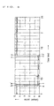
- an exciting pulse is applied to raise up a command pulse after a lapse of 1ms from a timing at which the command pulse falls as shown with a solid line in FIG. 6, the voltage applied across the piezoelectric elements, as shown with a solid line in FIG. 7, causes an overshoot, refer to a circle A, just after the command pulse has started to fall, and thereafter starts to oscillate with a resonance amplitude of about 20V.
- the exciting pulse in the prior art causes a resonance frequency in the voltage applied across the piezoelectric elements, which is defined by a design constant of the piezoelectric elements.
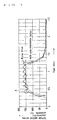
- an overshoot refer to a circle B, happens in a dimensional strain or displacement in the piezoelectric elements and also a mechanical oscillation having a resonance amplitude of about 30 ⁇ m, or a ringing, occurs in the piezoelectric elements.
- the resonance takes place owing to the ringing.
- the resonance in the piezoelectric elements becomes obstructive to the desired displacement and causes the dielectric breakdown across the terminals of the piezoelectric elements.
- the displacement in the piezoelectric elements does not damp immediately, but continues to oscillate even after the command pulse has raised up, or the exciting pulse is turned off.
- the prior piezoelectric actuator has for its technical subject to eliminate the overshoot in the voltage across the piezoelectric elements and in the displacement in the piezoelectric elements, and to prevent the ringing thereby preventing the occurrence of resonance phenomenon.
- the present invention is to overcome the above shortcomings to be solved, and to provide a piezoelectric actuator in which a superposing pulse is generated just after a command pulse has started to fall to make an overshoot less whereby a displacement in piezoelectric elements is reduced, and also to provide a fuel-injection apparatus incorporated with the same piezoelectric actuator.
- the present invention relates to a piezoelectric actuator in which an electric potential is applied across terminals of piezoelectric elements by turning on an exciting pulse to cause strains in dimension for the piezoelectric elements, the resultant strains are held for a preselected length of time, and thereafter the application of the electric potential ceases by turning off the exciting pulse whereby the piezoelectric elements are released from the strains in dimension, wherein, just after the exciting pulse is turned on, a pulse is superposed so as to turn off for a minute length of time.
- a pulse is superposed in synchronized with a timing at which the exciting pulse is turned on.
- the pulse is superposed in such a manner as to once turn off the exciting pulse in synchronized with the timing at which the exciting pulse is turned on, and again turn on the exciting pulse after a lapse of a minute length of time. This lessens the voltage across the piezoelectric elements and the overshoot of the displacement in the piezoelectric elements while reduces the oscillations thereof.
- an exciting pulse is also superposed for a minute length of time so as to once turn off the exciting pulse.
- the piezoelectric actuator is preferred, wherein the pulse superposed for the minute length of time is controlled so as to turn off with a timing less than one-fourth a period of an oscillation obtained as a characteristic and also turn on with the same timing. That is to say, the exciting pulse is preferably turned off within a minute period less than one-fourth a period of an oscillation, just after the exciting pulse has been turned off, and also turned on again after a lapse of the same period.
- the provision of the minute period has the great effect on diminishing the overshoot, which might otherwise happen at the initiation of displacement in the piezoelectric actuator, as well as reducing the oscillations in the displacement.
- the present invention is also concerned with a fuel-injection apparatus comprising; a body having discharge orifices to inject fuel, a needle valve movable in a reciprocating manner in a space in the body to thereby open and close at one end thereof the discharge orifices, a balance chamber in which the needle valve is exposed at its opposite end providing a pressure-exposed surface to bear a fuel pressure to regulate an amount of lift of the needle valve, a fuel path for supplying the fuel pressure into the balance chamber, a fuel-discharge passage for releasing the fuel pressure in the balance chamber, a valve for opening and closing the fuel-discharge passage, and an actuator for operating the valve, the actuator being of a piezoelectric actuator.
- the piezoelectric actuator of the present invention is controlled such that the exciting pulse is turned on at the start of the fuel injection and turned off at the end of the fuel injection.
- the piezoelectric actuator is superior in responsive characteristics of the occurrence and extinction of strains with respect to the switching-on and off of the electric potential and, therefore, able to start and cease injecting fuel without time lag on even the fuel-injection cycle that is very high in frequency for the high-speed engines.
- a pulse is superposed so as to once turn off the exciting pulse, immediately after the start of fuel injection, in synchronized with a timing at which the exciting pulse is turned on, and turn on again the exciting pulse after a lapse of a minute length of time.
- the piezoelectric actuator may be effectively protected from the dielectric breakdown.
- an exciting pulse is superposed so as to turn off the exciting pulse, just after having been turned on, for a minute length of time. This lessens the resonance amplitude at the timing of turning on the exciting pulse, which might be 20V in voltage and 30 ⁇ m in displacement, thus resulting in improving theaccuracy of defining the desired displacement.
- the fuel-injection apparatus having mounted with the piezoelectric actuator described above may be reduced in resonance oscillations with the result of improvement on the accuracy of the displacement in the actuator, and also protected against the dielectric breakdown across the terminals of the piezoelectric elements, thereby providing a very reliable and long-life fuel injectors.
- the fuel-injection apparatus of the present invention may operate rapidly so as to start and cease injecting fuel without time lag on even the fuel-injection cycle very high in frequency.
- the operating modes of the actuator-operated valve may be altered by regulating the timing, interval, strength and the like of the electric current applied to the piezoelectric elements, thereby varying the speed on lift of the needle valve depending on the engine operating conditions.
- This makes it possible to achieve reliably various characteristics on fuel-injection rating, especially, initial characteristics on fuel-injection rating, thereby diminishing the NOx emissions and noise from the engines.
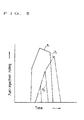
- FIG. 6 illustrates a waveform of an exciting pulse to control a piezoelectric actuator.
- the exciting pulse shown with a solid line is applied to piezoelectric elements, such that after having held for 1ms the event a command pulse had fallen or the exciting pulse had turned on, the command pulse is raised up or the exciting pulse is turned off.
- a voltage across the piezoelectric elements varies along a solid line in FIG. 7 while a displacement in the piezoelectric elements varies as shown in FIG. 8.
- the voltage across the piezoelectric elements starts to steeply arise just after the command pulse has fallen, causing an overshoot at an area circled at A in FIG.7, and thereafter continues to oscillate.
- the command pulse is superposed with the exciting pulse that is turned on and immediately thereafter turned off for a minute length of time. That is, the exciting pulse is once turned off synchronized with the "turn-on" timing of the exciting pulse and turned on again after a lapse of a minute time, which is a period less than one-fourth the period of the oscillation given as a characteristic of the piezoelectric actuator.
- the command pulse is once raised up, at a timing b in FIG. 6, within a length of time less than one-fourth the period of the oscillation of the piezoelectric actuator.
- the command pulse falls at a timing c in FIG. 6 and held at the last event, or the event the exciting pulse is turned on, for a little 1ms.
- the voltage across the piezoelectric elements may vary along a broken line in FIG. 7 while the displacement in the piezoelectric elements may vary as shown with a broken line in FIG. 8.
- the exciting pulse is superposed on the command pulse, just before turning on the command pulse, so as to turn off once and turn on again the command pulse after a lapse of a minute length of time. That is to say, immediately before the rise of command pulse, the command pulse once rise at a timing x in FIG. 6, then falls at a timing y after a minute length of time less than one-fourth the period of the oscillation of the piezoelectric actuator.
- This fuel-injection apparatus is suitably applicable to the common rail, fuel-injection system or pressure-accumulated, fuel-injection apparatus, not shown in the drawing.
- the fuel fed in an accumulator, referred to as "common rail” hereinafter, by a fuel injection pump is intensified in pressure in the common rail to the high pressure fuel, which is in turn charged out of injection nozzles of the fuel-injection apparatus into combustion chambers.
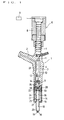
- an injector body 1 of the fuel-injection apparatus is hermetically attached in a bore, not shown in figures, provided in a base such as a cylinder head through a sealing member.
- the injector body 1 is hermetically mounted at the lower end thereof with a nozzle.
- the injector body 1 is formed at the upper shoulder thereof with a high-pressure fuel inlet 2.
- the injector 1 includes a middle section 3 provided therein with a space 4 extending axially of the injector body 1.
- a valve 5 for opening and closing a fuel-discharge passage 33, which will be described below.
- the valve 5 is designed to be driven by a piezoelectric actuator 6, which is composed of piezoelectric elements 7 laminated one on the other and accommodated in the injector body 1 with a fixing cap 8 screwed on the middle section 3.
- the piezoelectric elements 7 operate in response to control signals issued from a control unit 9 to drive the valve towards its open position.
- An output shaft 10 of the piezoelectric actuator 6 is extended from the piezoelectric elements 7 through the space 4 and further guided for sliding movement through a guide section 11 reduced radially with respect to the space 4 in the middle section 3, and a guide piece 12 arranged in the space 4 near the nozzle tip with respect to the guide section 11.
- the output shaft 10 may make a high-speed axial reciprocating movement under the operation of the piezoelectric elements 7 in the actuator 6.
- the piezoelectric actuator 6 is the same as described above in connection with FIGS. 6 to 8.
- the piezoelectric elements 7 in the actuator 6 are applied with an exciting pulse having a command pulse width corresponding to an operating duration of the injector.
- a command pulse width spanning from a pulse fall to a pulse rise is equal to the duration during which the injector is operated.
- the command pulse is kept at its pulse-fall phase for the duration of the injector operation, only during which a preselected exciting voltage is applied across the laminated piezoelectric elements 7 and thus an electric current flows through the piezoelectric elements 7, which are in turn caused to vary in distance between any adjoining elements to thereby produce a desired amount of variation in the total stroke.
- the variation in the total stroke makes the output shaft 10 force along its axial direction.
- the control member 13 is arranged interposed between the middle section 3 and a nozzle body 14. Both the control member 13 and the nozzle body 14 are united together to the middle section 3 to constitute a part of the injector body 1 by screwing a threaded cap 15, engaged with the nozzle body 14, onto the mating portion of the middle section 3.
- the nozzle body 14 is provided therein with a nozzle bore 16 in which a needle valve 17 is inserted for sliding movement so as to provide an annular clearance 18 therebetween.
- the clearance around the needle valve 17 forms a high-pressure fuel passage.
- the nozzle body 14 is formed at its tip with a discharge orifice 19 through which the fuel is injected into the combustion chambers of the internal combustion engine.
- the needle valve 17 has a tapered end.
- Axial reciprocating motion of the needle valve 17 causes the its tapered end to raise off and to reseat on a confronting tapered surface 20 at the tip of the nozzle bore 16 in the nozzle body 14, whereby the fuel flow to be injected out of the discharge orifice 19 may be allowed and blocked.
- the needle valve 17 has at the midway area thereof an annular tapered surface 21 that forms a pressure-exposed surface for bearing the fuel pressure acting in the direction where the needle valve 17 opens the discharge orifice. The instant the needle valve 17 is raised off the tapered surface 20, the high-pressure fuel may be injected out of the discharge orifice 19 into the combustion chamber. In contrast, when the needle valve 17 moves back down onto the tapered surface 20, the fuel flow is blocked and thus the fuel injection ceases.
- the fuel fed from the common rail, not shown, for the high-pressure supply source to the fuel inlet 2 flows through a fuel passage 22 in the injector body 1, a fuel passage 23 in the control member 13 and a fuel passage 24 in the nozzle body 14, and reaches the fuel sac 25 to which is exposed the tapered surface 21 for the pressure-exposed surface.
- the control member 13 has a hole 27 that is at the position offset radially outwardly with respect to the center thereof and in alignment with a hole 26 in the injector body 1.
- a connector pin 28 is inserted in the confronting holes 26, 27 to thereby keep the control member 13 in proper position relatively of the middle section 3.
- the control member 13 is further provided with a recess 29 opened facing to the nozzle body 14.
- the needle valve 17, explained in detail hereinafter, extends into the recess 29 and has at its end a pressure-exposed surface 31 to the fuel pressure, which cooperates with the recess 29 to define the balance chamber 30.
- the control member 13 is bored with a fuel path 32, which is open to the fuel passage 23 and extends radially to the center of the control member 13.
- the fuel path 32 communicates with the balance chamber 30 to feed the high-pressure fuel into the chamber 30.
- the fuel-discharge passage 33 is bored axially at the center of the control member 13 so as to communicate at one end thereof with the balance chamber 30 and at the opposite end with the axially extending space 4 in the middle section 3.
- the actuator-operated valve 5 includes a valve stem 34 connected integrally with the output shaft 10 of the piezoelectric actuator 6, and a return spring 35 to urge the valve stem 34 in a direction for closing the valve 5.
- the return spring 35 is abutted at its one end against a spring bearing 36 fixed to the valve stem 34 and at the opposite end against a top face 37 of the control member 13.
- the return spring 35 is fitted under compression to urge constantly the valve stem 34 upwards.
- the valve stem 34 extends through the fuel-discharge passage 33, leaving a small clearance therebetween, into the balance chamber 30.
- the valve stem 34 has at its end a tapered valve head 38 to open and close the fuel-discharge passage 33.
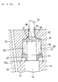
- the essential structures or components of the fuel-injection apparatus in FIG. 4 is substantially identical with that of the fuel-injection apparatus in FIG. 2, except for the type of the spring serving as means for biasing the needle valve 17 towards its closing position at which the fuel injection ceases, and therefore the details of the actuator-operated valve 5 will be explained below in connection with FIG. 4.
- the tapered valve head 38 has a tapered conical valve face 39 that may snugly match a valve seat 40 of a conical convex surface, which is formed in the fuel-discharge passage 33 at its end opened facing to the balance chamber 30.
- the piezoelectric actuator 6 When the piezoelectric actuator 6 is in nonconductive state or deenergized, the actuator-operated valve 5 is held by the spring force of the return spring 35 at its closure position where the valve face 38 of the tapered valve head 39 seats against the valve seat 40 in face-to-face contact relation, thereby blocking the fuel-discharge passage 33. With the piezoelectric actuator 6 turned into energization by the application of electric current, the valve stem 34 of the valve 5 moves downwards in the drawing, overcoming the spring force of the return spring 35.
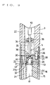
- a diaphragm spring 43 for return spring is interposed under compression between a corner 41 of the recess 29 and a spring bearing 42 attached to the axial end 44 of the needle valve 17.
- the diaphragm spring 43 forces the needle valve 17 to its closure position where the needle valve 17 blocks the fuel flow to the discharge orifice 19.
- Both the spring bearing 42 and the diaphragm spring 43 are formed with suitable holes, not shown, to allow the fuel pressure in the fuel path 32 to reach the balance chamber 30.
- the force of the fuel pressure in the balance chamber 30 acting on the pressure-exposed surface 31 of the needle valve 17 may control the lift of the valve head under balance with the fuel pressure exerted on the pressure-exposed surface of the tapered surface 21 of the needle valve 17 and the return force of the diaphragm spring 43 acting on the needle valve 17.
- the control member 13 is provided with a shoulder 47 for accommodate the spring bearing 42.
- the shoulder 47 is formed larger in depth by a distance H, compared to the thickness of the spring bearing 42.
- the distance H is equal to a distance spanning from the closure position to the open position of the needle valve 17, which may be thus movable within the range of between the closure and open positions.
- the open degree of the actuator-operated valve 5 upon opening the fuel-discharge passage 33 defines the extent of reduction of the fuel pressure in the balance chamber 30.
- the fuel also reaches the clearance 18 defined between the nozzle body 14 and the periphery of the needle valve 17 thereby to fill the clearance 18.
- the fuel pressure which is charged in the balance chamber 30 through the fuel path 32, acts on the pressure-exposed surface 31 of the needle valve 17.
- the resultant force of the return force of the diaphragm spring 43 with the force of the fuel pressure acting the pressure-exposed surface 31 to force the needle valve 17 to its closing position exceeds the force of the fuel pressure acting on the pressure-exposed surface of the tapered surface 21 to force the needle vale 17 to its open position and, therefore, the needle valve 17 closes the discharge orifice 19 whereby the fuel injection ceases.
- the instant a controller unit 9 energizes the piezoelectric actuator 6, the valve stem 34 is forced downwards in the drawing against the compression spring force of the return spring 35 to move the valve face 39 of the tapered valve head 38 off the valve seat 40 whereby the valve 5 opens the fuel-discharge passage 33.
- the fuel path 32 has the effect of an iris, which renders the flow of fuel in the fuel path 32 smaller than that in the fuel-discharge passage 33. Therefore, opening the fuel-discharge passage 33 relives the fuel pressure in the balance chamber 30 to the space 4.
- the force of the fuel pressure acting on the tapered surface 21 to force the needle valve 17 to its open position overcomes the resultant force of the return force of the diaphragm spring 43 with the force of the fuel pressure acting the pressure-exposed surface 31 to force the needle valve 17 to its closing position to thereby lift the needle vale 17 so that the fuel is injected out of the discharge orifice 19 into the combustion chambers.
- the effective open area of the fuel-discharge passage 33 opened by the actuator-operated valve 5 is designed less than the cross-sectional area of any other fuel-discharge passages after the balance chamber 30, the open degree of the actuator-operated valve 5 defines the magnitude of the fuel pressure in the balance chamber 30.
- the balance chamber 30 is applied the fuel pressure from the fuel path 32 thereby restoring the fuel pressure therein and, consequently, the needle valve 17 stops the fuel injection.
- the restored fuel pressure acts on the tapered valve head 38 to consequently urge, in addition to the force of the return spring 35, the valve face 39 against the its seat 40. It will be understood that the higher the fuel pressure in the balance chamber 30 is, the greater is the force closing the actuator-operated valve 5, which may thus block certainly the fuel leakage.
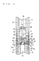
- a coiled spring 46 is used for the return spring to force the valve 5 toward the closure position.
- Like numerals designate identical or corresponding components or parts throughout FIGS. 2 and 3 and, therefore, the previous description is applicable.
- the coiled spring 46 in the embodiment shown in FIG. 3 is contained in the balance chamber 30 with its one end being abutted against the spring bearing 42 and the opposite end being a bottom face of the recess 29.
- the coiled spring 46 has no difference in the function of return spring from the diaphragm spring 43.
- the coiled spring 46 may use without any modification the bottom face of the recess 29 for the spring bearing surface and, therefore, has the advantage of not having to form the corner 41 in the recess 29, which is required for the diaphragm spring 43.
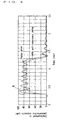
- FIG. 5 illustrates fuel-injection ratings per one fuel-injection cycle, which are obtained by a conventional instrument for measuring the fuel-injection rating.
- a curve f1 shows the fuel-injection rating of the needle valve 17 in a fuel-injection cycle in which the piezoelectric elements 7 in the piezoelectric actuator 6 are applied with a high voltage. It will be found that, as the electricity is supplied, the fuel-injection rating increases steeply. In contrast, when applying a low voltage to the piezoelectric elements 7, the fuel-injection rating increases slowly, as shown with a curve f2, as the electricity is supplied.
- the fuel injection may be stopped at low fuel-injection rating, as shown in a curve f3.
- the fuel-injection rating may be easily controlled by regulating the timing, interval, strength and the like of the electricity applied to the piezoelectric elements 7, depending on the engine operating conditions such as engine load.
Landscapes
- Engineering & Computer Science (AREA)
- Chemical & Material Sciences (AREA)
- Combustion & Propulsion (AREA)
- Mechanical Engineering (AREA)
- General Engineering & Computer Science (AREA)
- Physics & Mathematics (AREA)
- Fluid Mechanics (AREA)
- Fuel-Injection Apparatus (AREA)
- Electrical Control Of Air Or Fuel Supplied To Internal-Combustion Engine (AREA)
- General Electrical Machinery Utilizing Piezoelectricity, Electrostriction Or Magnetostriction (AREA)
Applications Claiming Priority (2)
| Application Number | Priority Date | Filing Date | Title |
|---|---|---|---|
| JP10186665A JP2000023474A (ja) | 1998-07-01 | 1998-07-01 | 圧電アクチュエータ及びそれを用いた燃料噴射装置 |
| JP18666598 | 1998-07-01 |
Publications (3)
| Publication Number | Publication Date |
|---|---|
| EP0995899A2 true EP0995899A2 (fr) | 2000-04-26 |
| EP0995899A3 EP0995899A3 (fr) | 2001-05-30 |
| EP0995899B1 EP0995899B1 (fr) | 2005-02-02 |
Family
ID=16192535
Family Applications (1)
| Application Number | Title | Priority Date | Filing Date |
|---|---|---|---|
| EP99305113A Expired - Lifetime EP0995899B1 (fr) | 1998-07-01 | 1999-06-29 | Dispositif d'actionnement piézoélectrique et appareil d'injection de carburant utilisant le dispositif |
Country Status (4)
| Country | Link |
|---|---|
| US (1) | US6155500A (fr) |
| EP (1) | EP0995899B1 (fr) |
| JP (1) | JP2000023474A (fr) |
| DE (1) | DE69923516T2 (fr) |
Cited By (7)
| Publication number | Priority date | Publication date | Assignee | Title |
|---|---|---|---|---|
| WO2006069750A1 (fr) * | 2004-12-23 | 2006-07-06 | Siemens Vdo Automotive Ag | Procede et dispositif de compensation des effets de rebond dans un systeme d'injection a commande piezo-electrique d'un moteur a combustion interne |
| EP1860310A2 (fr) | 2006-05-23 | 2007-11-28 | Delphi Technologies, Inc. | Procédé pour faire fonctionner un injecteur de carburant |
| WO2009115360A1 (fr) | 2008-03-18 | 2009-09-24 | Robert Bosch Gmbh | Procédé pour empêcher les chocs d’une soupape commandée à l’aide d’un actionneur piézoélectrique |
| EP2149695A3 (fr) * | 2002-09-23 | 2010-10-20 | Delphi Technologies Holding S.à.r.l. | Système d'injection |
| DE102010063667A1 (de) * | 2010-12-21 | 2012-06-21 | Continental Automotive Gmbh | Geräuschreduzierendes Ansteuerverfahren für einen Piezoaktor in einem Injektor |
| WO2014117897A1 (fr) * | 2013-02-04 | 2014-08-07 | Continental Automotive Gmbh | Procédé de détermination de la température d'un carburant |
| WO2018002177A1 (fr) * | 2016-06-29 | 2018-01-04 | Koninklijke Philips N.V. | Actionneur en polymère électro-actif (eap) et procédé d'entrainement |
Families Citing this family (10)
| Publication number | Priority date | Publication date | Assignee | Title |
|---|---|---|---|---|
| US6886898B2 (en) * | 2001-11-30 | 2005-05-03 | Sharp Kabushiki Kaisha | Driving method of piezoelectric elements, ink-jet head, and ink-jet printer |
| US6811093B2 (en) * | 2002-10-17 | 2004-11-02 | Tecumseh Products Company | Piezoelectric actuated fuel injectors |
| GB0616713D0 (en) * | 2006-08-23 | 2006-10-04 | Delphi Tech Inc | Piezoelectric fuel injectors |
| EP1956221B1 (fr) * | 2007-02-02 | 2009-12-02 | Delphi Technologies, Inc. | Procédé de fonctionnement d'un actionneur piézoélectrique |
| JP2009089517A (ja) * | 2007-09-28 | 2009-04-23 | Olympus Corp | 超音波モータの駆動装置 |
| JP5752410B2 (ja) * | 2010-12-27 | 2015-07-22 | 株式会社 Acr | ディーゼルエンジン用のユニットインジェクタ |
| BR112014026011B1 (pt) * | 2012-04-20 | 2021-09-28 | Mechano Transformer Corporation | Válvula pizoelétrica e separador ótico de material particulado provido com meios de sopro de ar que utiliza válvula pizoelétrica |
| DE102012214565B4 (de) * | 2012-08-16 | 2015-04-02 | Continental Automotive Gmbh | Verfahren und Vorrichtung zum Betreiben eines Einspritzventils |
| JP6011193B2 (ja) * | 2012-09-21 | 2016-10-19 | Tdk株式会社 | 駆動装置 |
| DE102017218869A1 (de) * | 2017-10-23 | 2019-04-25 | Robert Bosch Gmbh | Injektor |
Family Cites Families (5)
| Publication number | Priority date | Publication date | Assignee | Title |
|---|---|---|---|---|
| US4641053A (en) * | 1984-08-14 | 1987-02-03 | Matsushita Seiko Co., Ltd. | Ultrasonic liquid atomizer with an improved soft start circuit |
| JPS6372381A (ja) * | 1986-09-17 | 1988-04-02 | 株式会社日本自動車部品総合研究所 | 容量性負荷の駆動方法 |
| JPH01187363A (ja) * | 1988-01-21 | 1989-07-26 | Toyota Motor Corp | 内燃機関用燃料噴射弁 |
| JP3740733B2 (ja) * | 1996-02-13 | 2006-02-01 | いすゞ自動車株式会社 | 内燃機関の燃料噴射装置 |
| JP3823391B2 (ja) * | 1996-08-31 | 2006-09-20 | いすゞ自動車株式会社 | エンジンの燃料噴射装置 |
-
1998
- 1998-07-01 JP JP10186665A patent/JP2000023474A/ja active Pending
-
1999
- 1999-06-28 US US09/340,163 patent/US6155500A/en not_active Expired - Fee Related
- 1999-06-29 DE DE69923516T patent/DE69923516T2/de not_active Expired - Fee Related
- 1999-06-29 EP EP99305113A patent/EP0995899B1/fr not_active Expired - Lifetime
Cited By (18)
| Publication number | Priority date | Publication date | Assignee | Title |
|---|---|---|---|---|
| EP2149695A3 (fr) * | 2002-09-23 | 2010-10-20 | Delphi Technologies Holding S.à.r.l. | Système d'injection |
| US8239115B2 (en) | 2004-12-23 | 2012-08-07 | Continental Automotive Gmbh | Method and device for offsetting bounce effects in a piezo-actuated injection system of an internal combustion engine |
| WO2006069750A1 (fr) * | 2004-12-23 | 2006-07-06 | Siemens Vdo Automotive Ag | Procede et dispositif de compensation des effets de rebond dans un systeme d'injection a commande piezo-electrique d'un moteur a combustion interne |
| EP1860310A2 (fr) | 2006-05-23 | 2007-11-28 | Delphi Technologies, Inc. | Procédé pour faire fonctionner un injecteur de carburant |
| EP1860310A3 (fr) * | 2006-05-23 | 2008-08-27 | Delphi Technologies, Inc. | Procédé pour faire fonctionner un injecteur de carburant |
| US7856963B2 (en) | 2006-05-23 | 2010-12-28 | Delphi Technologies Holding S.Arl | Method of operating a fuel injector |
| CN101978202B (zh) * | 2008-03-18 | 2013-04-24 | 罗伯特.博世有限公司 | 由压电致动器开关的阀门的跳动抑制方法 |
| WO2009115360A1 (fr) | 2008-03-18 | 2009-09-24 | Robert Bosch Gmbh | Procédé pour empêcher les chocs d’une soupape commandée à l’aide d’un actionneur piézoélectrique |
| US8578896B2 (en) | 2008-03-18 | 2013-11-12 | Robert Bosch Gmbh | Method for bounce suppression of a valve switched by a piezo actuator |
| DE102010063667A1 (de) * | 2010-12-21 | 2012-06-21 | Continental Automotive Gmbh | Geräuschreduzierendes Ansteuerverfahren für einen Piezoaktor in einem Injektor |
| US8800535B2 (en) | 2010-12-21 | 2014-08-12 | Continental Automotive Gmbh | Noise-reduced actuation method for a piezoactuator in an injector |
| DE102010063667B4 (de) | 2010-12-21 | 2018-11-22 | Continental Automotive Gmbh | Geräuschreduzierendes Ansteuerverfahren für einen Piezoaktor in einem Injektor |
| WO2014117897A1 (fr) * | 2013-02-04 | 2014-08-07 | Continental Automotive Gmbh | Procédé de détermination de la température d'un carburant |
| US9829394B2 (en) | 2013-02-04 | 2017-11-28 | Continental Automotive Gmbh | Method for determining the fuel temperature |
| WO2018002177A1 (fr) * | 2016-06-29 | 2018-01-04 | Koninklijke Philips N.V. | Actionneur en polymère électro-actif (eap) et procédé d'entrainement |
| WO2018001839A1 (fr) * | 2016-06-29 | 2018-01-04 | Koninklijke Philips N.V. | Actionneur à eap et procédé d'excitation |
| JP2019520709A (ja) * | 2016-06-29 | 2019-07-18 | コーニンクレッカ フィリップス エヌ ヴェKoninklijke Philips N.V. | Eapアクチュエータおよび駆動方法 |
| US11362258B2 (en) | 2016-06-29 | 2022-06-14 | Koninklijke Philips N.V. | EAP actuator and drive method |
Also Published As
| Publication number | Publication date |
|---|---|
| EP0995899A3 (fr) | 2001-05-30 |
| EP0995899B1 (fr) | 2005-02-02 |
| DE69923516T2 (de) | 2006-02-09 |
| US6155500A (en) | 2000-12-05 |
| JP2000023474A (ja) | 2000-01-21 |
| DE69923516D1 (de) | 2005-03-10 |
Similar Documents
| Publication | Publication Date | Title |
|---|---|---|
| EP0995899B1 (fr) | Dispositif d'actionnement piézoélectrique et appareil d'injection de carburant utilisant le dispositif | |
| EP1382836B1 (fr) | Injecteur à combustible | |
| US6837221B2 (en) | Fuel injector with feedback control | |
| US6253736B1 (en) | Fuel injector nozzle assembly with feedback control | |
| KR100561791B1 (ko) | 연료분사장치 | |
| US5860597A (en) | Injection rate shaping nozzle assembly for a fuel injector | |
| US6705551B1 (en) | Common rail injector | |
| US6267306B1 (en) | Fuel injector including valve needle, injection control valve, and drain valve | |
| RU2193683C2 (ru) | Гидрораспределительный клапан | |
| US6012430A (en) | Fuel injector | |
| EP1163440B1 (fr) | Injecteur de carburant | |
| EP1098087B1 (fr) | Injecteur de combustible | |
| US6209524B1 (en) | Fuel-injection apparatus | |
| EP0892171B1 (fr) | Injecteur asservi associé à une rampe d'alimentation commune | |
| US7150410B1 (en) | Method for providing a controlled injection rate and injection pressure in a fuel injector assembly | |
| US6439483B2 (en) | Variable orifice electronically controlled common rail injector (VOECRRI) | |
| JPH0467026B2 (fr) | ||
| GB2366664A (en) | Control method for a piezoelectric fuel injector | |
| WO2005054655A2 (fr) | Procede destine a reguler la vitesse d'injection et la pression d'injection dans un ensemble injecteur de carburant | |
| JP2632713B2 (ja) | 燃料噴射装置 | |
| JP4134968B2 (ja) | 燃料噴射ノズル | |
| EP1024281A2 (fr) | Procédé et dispositif pour fournir un taux et une pression d'injection réglables dans un injecteur de combustible | |
| JP3760572B2 (ja) | エンジンの燃料噴射装置 | |
| JP2008144635A (ja) | 燃料噴射弁 | |
| JPH0230975A (ja) | 燃料噴射弁 |
Legal Events
| Date | Code | Title | Description |
|---|---|---|---|
| PUAI | Public reference made under article 153(3) epc to a published international application that has entered the european phase |
Free format text: ORIGINAL CODE: 0009012 |
|
| AK | Designated contracting states |
Kind code of ref document: A2 Designated state(s): DE FR GB |
|
| AX | Request for extension of the european patent |
Free format text: AL;LT;LV;MK;RO;SI |
|
| PUAL | Search report despatched |
Free format text: ORIGINAL CODE: 0009013 |
|
| AK | Designated contracting states |
Kind code of ref document: A3 Designated state(s): AT BE CH CY DE DK ES FI FR GB GR IE IT LI LU MC NL PT SE |
|
| AX | Request for extension of the european patent |
Free format text: AL;LT;LV;MK;RO;SI |
|
| 17P | Request for examination filed |
Effective date: 20010906 |
|
| AKX | Designation fees paid |
Free format text: DE FR GB |
|
| GRAP | Despatch of communication of intention to grant a patent |
Free format text: ORIGINAL CODE: EPIDOSNIGR1 |
|
| GRAS | Grant fee paid |
Free format text: ORIGINAL CODE: EPIDOSNIGR3 |
|
| GRAA | (expected) grant |
Free format text: ORIGINAL CODE: 0009210 |
|
| AK | Designated contracting states |
Kind code of ref document: B1 Designated state(s): DE FR GB |
|
| REG | Reference to a national code |
Ref country code: GB Ref legal event code: FG4D |
|
| REF | Corresponds to: |
Ref document number: 69923516 Country of ref document: DE Date of ref document: 20050310 Kind code of ref document: P |
|
| PLBE | No opposition filed within time limit |
Free format text: ORIGINAL CODE: 0009261 |
|
| STAA | Information on the status of an ep patent application or granted ep patent |
Free format text: STATUS: NO OPPOSITION FILED WITHIN TIME LIMIT |
|
| ET | Fr: translation filed | ||
| 26N | No opposition filed |
Effective date: 20051103 |
|
| PGFP | Annual fee paid to national office [announced via postgrant information from national office to epo] |
Ref country code: DE Payment date: 20070524 Year of fee payment: 9 |
|
| PGFP | Annual fee paid to national office [announced via postgrant information from national office to epo] |
Ref country code: GB Payment date: 20070517 Year of fee payment: 9 |
|
| PGFP | Annual fee paid to national office [announced via postgrant information from national office to epo] |
Ref country code: FR Payment date: 20070515 Year of fee payment: 9 |
|
| GBPC | Gb: european patent ceased through non-payment of renewal fee |
Effective date: 20080629 |
|
| REG | Reference to a national code |
Ref country code: FR Ref legal event code: ST Effective date: 20090228 |
|
| PG25 | Lapsed in a contracting state [announced via postgrant information from national office to epo] |
Ref country code: DE Free format text: LAPSE BECAUSE OF NON-PAYMENT OF DUE FEES Effective date: 20090101 |
|
| PG25 | Lapsed in a contracting state [announced via postgrant information from national office to epo] |
Ref country code: GB Free format text: LAPSE BECAUSE OF NON-PAYMENT OF DUE FEES Effective date: 20080629 |
|
| PG25 | Lapsed in a contracting state [announced via postgrant information from national office to epo] |
Ref country code: FR Free format text: LAPSE BECAUSE OF NON-PAYMENT OF DUE FEES Effective date: 20080630 |