EP0996294A2 - Méthode et appareil de traitement de signal audio - Google Patents
Méthode et appareil de traitement de signal audio Download PDFInfo
- Publication number
- EP0996294A2 EP0996294A2 EP99120007A EP99120007A EP0996294A2 EP 0996294 A2 EP0996294 A2 EP 0996294A2 EP 99120007 A EP99120007 A EP 99120007A EP 99120007 A EP99120007 A EP 99120007A EP 0996294 A2 EP0996294 A2 EP 0996294A2
- Authority
- EP
- European Patent Office
- Prior art keywords
- signal
- audio signal
- receiver
- audio
- television
- Prior art date
- Legal status (The legal status is an assumption and is not a legal conclusion. Google has not performed a legal analysis and makes no representation as to the accuracy of the status listed.)
- Withdrawn
Links
- 230000005236 sound signal Effects 0.000 title claims abstract description 182
- 238000000034 method Methods 0.000 title claims abstract description 35
- 238000012545 processing Methods 0.000 title claims description 21
- DFPAKSUCGFBDDF-UHFFFAOYSA-N Nicotinamide Chemical compound NC(=O)C1=CC=CN=C1 DFPAKSUCGFBDDF-UHFFFAOYSA-N 0.000 claims abstract 3
- 230000008569 process Effects 0.000 claims description 7
- 238000001514 detection method Methods 0.000 claims description 6
- 101000959126 Xenopus laevis Peptidyl-alpha-hydroxyglycine alpha-amidating lyase B Proteins 0.000 claims 6
- -1 PAL-G Proteins 0.000 claims 3
- 230000009977 dual effect Effects 0.000 abstract description 4
- 230000006870 function Effects 0.000 abstract description 3
- 230000006798 recombination Effects 0.000 description 9
- 238000005215 recombination Methods 0.000 description 9
- 238000000926 separation method Methods 0.000 description 4
- 230000011664 signaling Effects 0.000 description 4
- 238000010586 diagram Methods 0.000 description 3
- 238000001914 filtration Methods 0.000 description 2
- 208000037656 Respiratory Sounds Diseases 0.000 description 1
- 230000004075 alteration Effects 0.000 description 1
- 238000004891 communication Methods 0.000 description 1
- 230000001934 delay Effects 0.000 description 1
- 238000013461 design Methods 0.000 description 1
- 230000008030 elimination Effects 0.000 description 1
- 238000003379 elimination reaction Methods 0.000 description 1
- 238000011835 investigation Methods 0.000 description 1
- 238000012986 modification Methods 0.000 description 1
- 230000004048 modification Effects 0.000 description 1
- 230000005855 radiation Effects 0.000 description 1
- 230000004044 response Effects 0.000 description 1
- 238000006467 substitution reaction Methods 0.000 description 1
Images


Classifications
-
- H—ELECTRICITY
- H04—ELECTRIC COMMUNICATION TECHNIQUE
- H04N—PICTORIAL COMMUNICATION, e.g. TELEVISION
- H04N5/00—Details of television systems
- H04N5/44—Receiver circuitry for the reception of television signals according to analogue transmission standards
- H04N5/60—Receiver circuitry for the reception of television signals according to analogue transmission standards for the sound signals
- H04N5/602—Receiver circuitry for the reception of television signals according to analogue transmission standards for the sound signals for digital sound signals
-
- H—ELECTRICITY
- H04—ELECTRIC COMMUNICATION TECHNIQUE
- H04N—PICTORIAL COMMUNICATION, e.g. TELEVISION
- H04N21/00—Selective content distribution, e.g. interactive television or video on demand [VOD]
- H04N21/40—Client devices specifically adapted for the reception of or interaction with content, e.g. set-top-box [STB]; Operations thereof
- H04N21/43—Processing of content or additional data, e.g. demultiplexing additional data from a digital video stream; Elementary client operations, e.g. monitoring of home network or synchronising decoder's clock; Client middleware
- H04N21/439—Processing of audio elementary streams
- H04N21/4396—Processing of audio elementary streams by muting the audio signal
-
- H—ELECTRICITY
- H04—ELECTRIC COMMUNICATION TECHNIQUE
- H04N—PICTORIAL COMMUNICATION, e.g. TELEVISION
- H04N21/00—Selective content distribution, e.g. interactive television or video on demand [VOD]
- H04N21/80—Generation or processing of content or additional data by content creator independently of the distribution process; Content per se
- H04N21/81—Monomedia components thereof
- H04N21/8106—Monomedia components thereof involving special audio data, e.g. different tracks for different languages
Definitions
- This invention relates in general to controlling audio anomalies and in particular to controlling audio anomalies in signals which have an auxiliary audio signal or dual language audio signal adjacent to a main audio signal.
- Audio anomalies occur in a variety of signals such as in the television signals of a television system which has an auxiliary audio signal adjacent to a main audio signal.
- An understanding of the system in which a signal occurs can help define the causes of the audio anomalies.
- a television system is used to illustrate the audio anomalies which occur with a signal having an auxiliary audio signal adjacent to a main audio signal.
- Television system 10 as illustrated in FIG. 1, includes a headend 14 which receives input programming from input sources 12 (a-c). Headend 14 combines the programming from the various input sources 12 (a-c) into a television signal with multiple channels and modulates and distributes the television signal to subscriber locations (e.g., subscriber location 17) via distribution system 16.
- subscriber locations e.g., subscriber location 17
- the audio options associated with the multiple channels will vary. Some channels will be available in either monophonic or stereo sound, others will only be available in monophonic sound. Some channels may have an optional second audio language.
- an intermediate device such as a home communication terminal (HCT) 18 or a set-top, interfaces to distribution system 16 and to receiver 19.
- HCT home communication terminal
- Receiver 19 can be a monophonic television, a stereo television, an audio only stereo receiver, or a computer.
- HCT 18 allows access to the auxiliary audio options as an additional service of television system 10.
- the options are unique to each television system 10.
- a television system 10 may have auxiliary audio signaling on all channels, such as a second audio language for every channel.
- Another television system 10 may have no auxiliary audio signaling, while another may have auxiliary audio signaling on one or more channels.
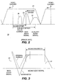
- FIG. 2 is a graphic representation illustrating the components of a single channel within multi-channel television signal 20 having auxiliary audio signal 21 adjacent to main audio signal 22.
- the components also include video signal 24 and color signal 26.
- the auxiliary audio signal 21 is provided because additional languages and stereo sound are available and in demand by subscribers paying for access to television signal 20.
- the auxiliary audio signal 21 may be, for example, Near Instantaneously Companded Audio Multiplex (NICAM) audio signals or dual language audio signals. It is important to note that, even in systems designed for multiple audio signals, auxiliary audio signal 21 may not be present on every programming channel in television signal 20.
- a set-top, HCT 18, or any television can process main audio signal 22.
- the reception or processing of auxiliary audio signal 21 can be limited by several factors such as the type of receiver 19, system controlled conditional access within television system 10, and the availability of additional audio on auxiliary audio signal 21.
- the multiple channels occur at a set spacing based on the format of television signal 20.
- PAL-B Phase Alteration (by) Line type B
- PAL-G Phase Alteration (by) Line type B
- the location of television signal 20 components is also fixed within the total channel allocation based on the format.
- the location of main audio signal 22 is offset from the video signal by a fixed frequency.
- NTSC National Television System Committee
- a PAL-I format uses a 6.0 MHz frequency offset
- PAL-B and PAL-G formats use a 5.5 MHz frequency offset.
- Audio anomalies are most prevalent in PAL-B, PAL-G, and PAL-B/G hybrid formats due to the close channel spacing, but have occurred in other formats such as PAL-I.
- a PAL-B signal format is used for all examples unless stated otherwise.
- additional limitations such as a total channel allocation of only 7 MHz impacts the audio signals.
- the main audio signal 22 is frequency offset from the video carrier by 5.5 MHz.
- the auxiliary audio signal 21 is frequency offset from the video carrier by 5.85 MHz. With limited space within the total channel allocation, the auxiliary audio signal 21 is located at only 350 Kilohertz (KHz ) above the main audio signal 22.
- auxiliary audio signal 21 is located at 552 KHz above the main audio signal 22.
- the close spacing of the two audio signals is not a problem as the main audio signal 22 would occur right at 5.5 MHz, however when the main audio signal 22 is modulated there is a spread around 5.5 MHz as shown by the shaded region in FIG. 2.
- the close proximity of the two audio signals in a PAL-B or PAL-G system creates audio anomalies when filtering out one audio signal to receive the other.
- Audio whistle occurs when a portion of the main audio signal 22 is processed through the auxiliary audio signal processing circuitry or when signal interference occurs due to the layout of the components within HCT 38. Due to the close proximity of the two signals, filters designed to isolate the auxiliary audio signal 21 capture a small portion of the spread main audio signal 22, for example a portion of the main audio signal 22 at 5.5 MHz. Thus, when the signals are recombined in the output of HCT 18, there are two components of the 5.5 MHz main audio signal 22 with different amplitudes and only slightly different or the same frequencies.
- One of the components is generated by processing main audio signal 22.
- the other component is the portion of the main audio signal 22 that was processed through the auxiliary audio signal 21 circuitry.
- the additional component results in the generation of a constant tone signal, the audio whistle. Attempts to eliminate audio whistle have resulted in the creation of additional problems.
- One proposed solution involves locking the main audio signal 22 output frequency to the main audio signal 22 input 5.5 frequency. This solution was unsuccessful as the main audio signal 22 input when modulated had signal spread and the resultant signal lock constantly shifted resulting in a loss of volume control.
- a second proposed solution involved designing a deeper notch separating the two signals.
- a deeper notch or gap between the main audio signal 22 and the auxiliary audio signal 21 allows easier separation of the two signals. Easier separation allows for an easier removal of the main audio signal 22 in the auxiliary audio signal 21 processing circuitry, thus no additional main audio signal 22 component remains in the recombined signal.
- the present invention provides a method, apparatus, and system for controlling audio anomalies in signals such as television signals, that have a first and second audio signal or multiple audio signals. Multiple audio signals include examples such as an auxiliary audio signal 21 adjacent to a main audio signal 22.
- the present invention provides a method for controlling audio whistle and audio pop in PAL-B, PAL-G, and PAL-B/G hybrid television systems with NICAM digital stereo audio signals.
- a PAL-B/G hybrid format includes a portion of the television signal formatted in the PAL-B format and a portion of the television signal formatted in the PAL-G format.
- This exemplary embodiment includes a method for separating and processing auxiliary audio signal 21 and for preventing the recombination of auxiliary audio signal 21 with the output of HCT 18. Based on the presence of auxiliary audio signal 21 and receiver 19 type, recombination is allowed or disallowed.
- FIG. 3 is a graphic representation illustrating the impact of a deeper notch on a NICAM audio signal.
- a deeper notch is created using sound traps, filters, or by other methods well known in the art.
- the deeper notch does reduce the introduction of main audio signal 22 into the auxiliary audio signal processing.
- the deeper notch also narrows the NICAM filter bandwidth, as shown by the shaded region in FIG. 3, causing excessive group delay in the NICAM signal.
- NICAM detection circuitry in receiver 19 shifts to the main audio signal 22 when no NICAM signal is detected or when NICAM signal distortion occurs due to excessive group delay. It was discovered that the excessive group delay results in the NICAM circuitry in receiver 19 shifting rapidly between main audio signal 22 and the NICAM formatted auxiliary audio signal 20. The rapid shift causes audio pop.
- auxiliary audio signal 21 and a HCT 18 or set-top processing auxiliary audio signal 21 prior to receiver 19.
- the audio anomalies occur in these systems when a stereo television tunes to a channel with only monophonic audio or when a monophonic television tunes to a channel with an auxiliary audio signal 21.
- the present invention provides an easy to implement and cost effective solution to audio anomalies without introducing additional problems into HCT 18.
- the introduction of circuitry to selectively eliminate the recombination of auxiliary audio signal 21 into the signal being output from HCT 18 to receiver 19, provides this easy and cost effective solution.
- the elimination of the output of auxiliary audio signal 21 is based on the type of receiver 19 connected to HCT 18 and on the presence of an auxiliary audio signal 21.
- the NICAM processing circuitry shown in an exemplary embodiment is typical of auxiliary audio processing circuitry but the present invention is not so limited as to the circuitry shown.
- Other methods of processing an auxiliary audio signal 21 and methods of preventing the recombination of auxiliary audio signal 21 with the output to receiver 19 are well known in the art.
- the present invention would work with the inclusion of a notch filter in the auxiliary audio processing circuitry, with different types of auxiliary audio detection circuitry, or with different methods of determining the type of receiver 19 attached to HCT 18.
- the present invention also works with different types of auxiliary audio signal 21 formats such as the NICAM format and formats for a second audio language signal.
- the circuitry required for processing auxiliary audio signal 21 can be comprised of any of a multitude of devices or combinations of devices such as band pass filters, amplifiers, and sound traps.
- the type and configuration of the devices will vary based on the type and format of the auxiliary audio signal 21 to be processed and the processing required.
- the circuitry and devices for detecting the presence of an auxiliary audio signal 21, for receiving input of the type of receiver 19 to which the auxiliary audio signals 21 will be output, for preventing the output of auxiliary audio signal 21 to the receiver 19 can also be varied.
- FIG. 4 is a representation of the portion of HCT 18 of FIG. 1 which processes incoming audio signals and selectively eliminates the recombination of auxiliary audio signal 21 into the signal being output from HCT 18 to receiver 19, in accordance with the present invention.
- FIG. 4 illustrates, in block diagram fashion, an apparatus for controlling audio anomalies, including a 5.85 MHz band pass filter 48, signal level detector 52, mute switch 51, amplifier 49, sound trap 50, comparator 53, and microprocessor unit (MPU) 54 of the present invention.
- the input signal 41 from distribution system 16 is received and adjusted for demodulation by a device such as up/down converter 42.
- the video demodulator 43 sends the demodulated baseband video component to RF modulator 45 for recombination with the other components of television signal 20 and for RF modulation.
- Inter-carrier detector 44 sends television signal 20 to 5.5 MHz band pass filter 46 for main audio signal 22 separation and modulation.
- the main audio signal 22 portion of television signal 20 is passed from the 5.5 MHz band pass filter 46 to a frequency modulation (FM) demodulator 47 and then to the RF modulator 45 for recombination with the other components of television signal 20, for RF modulation, and for output to receiver 19.
- FM frequency modulation
- the auxiliary audio signal 21 portion of television signal 20 is also separated and modified within HCT 19.
- Inter-carrier detector 44 also sends at least a portion of television signal 20 to 5.85 MHz band pass filter 48 for auxiliary audio signal 21 separation.
- the 5.85 MHz band pass filter 48 separates out signals in a range around the 5.85 auxiliary audio carrier and passes the signals within the range to amplifier 49.
- the signals are amplified at amplifier 49 to improve detection of auxiliary audio signal 21.
- the signal is then passed to mute switch 21 and to sound trap 50. Based on the setting of mute switch 21 the signal is or is not passed to RF modulator 45 for recombination with the other components of television signal 20, for RF modulation, and for output to receiver 19.
- the setting of mute switch is determined by both the detection of an auxiliary audio signal 21 and by the type of receiver 19 to which the RF output will go.
- the detection of an auxiliary audio signal 21 for a particular channel is achieved by sound trap 50, signal level detector 52, and comparator 53.
- the signal is run through sound trap 50 to reduce the amplitude of any signal around 5.5 MHz where any remaining portions of the main audio signal 22 would be and then passed to signal level detector 52.
- Signal level detector 52 indicates the strength of the signal received from sound trap 50 in the bandwidth of the auxiliary audio signal 21.
- Signal level detector 52 outputs a signal to comparator 53.
- Comparator 53 determines if the strength of the signal, as received from signal level detector 52, indicates the presence of auxiliary audio signal 21. If the signal level indicates auxiliary audio signal 21 is present, the comparator 53 signals mute switch 51 to allow the output of auxiliary audio signal 21 to RF modulator 45.
- Mute switch 51 requires an allowable indication from both comparator 53 and from MPU 54 before it allows the output of auxiliary audio signal 21.
- the normal position of mute switch 51 is muted or output disallowed.
- the signal from comparator 53 to mute switch 51 solves the problem of audio whistle when a stereo television tunes to a channel with only monophonic audio by eliminating the output of auxiliary audio signal 21 to RF modulator 45 when auxiliary audio signal 21 is not present.
- the auxiliary audio processing circuitry in the stereo television does not try to tune to the auxiliary audio signal 21 because no auxiliary audio signal 21 is output from HCT 18.
- MPU 54 receives input 55 as to the type of receiver 19 connected to HCT 18.
- the input 55 can be provided in many ways. For example, input 55 can be provided directly to HCT 18 via HCT 18 front panel keystrokes by the subscriber. Input 55 could be provided via infra-red radiation (IR) input by the subscriber to HCT 18 from a remote control device based on a set-up display screen displayed on a television. If input 55 indicates to MPU 54 that the receiver 19 is a stereo receiver, MPU 54 signals mute switch 51 to be controlled only by comparator 53.
- IR infra-red radiation
- MPU 54 signals mute switch 51 to always disallow or mute auxiliary audio signal 21.
- the instruction from MPU 54 to mute switch 51 solves the problem of audio whistle on monophonic televisions in television system 30 when auxiliary audio signal 21 is adjacent to a main audio signal 22.
- mute switch 51 disallows output of auxiliary audio signal 21 even if comparator 53 indicates an auxiliary audio signal 21 is present.
- No auxiliary audio signal 21 is output from HCT 18 to cause audio anomalies on the monophonic television.
- RF modulator 45 recombines the baseband video, the FM demodulated main audio signal 22, and, when allowed by mute switch 54, the auxiliary audio signal 21 into a RF output 56 to receiver 19.
- the present invention allows HCT 18 in television system 10 with auxiliary audio signal 21 on one or more channels and with multiple receiver 19 types to eliminate audio anomalies. Additionally, HCT 18 with the present invention can function in television system 10 when none of the channels have auxiliary audio signal 21 or any additional audio options.
- the present invention can be applied to other audio signaling and formats such as stereo audio signals and multiple music channels, and to other television formats such as Pal-I.
- the present invention provides a method for controlling audio anomalies in signals which may have an auxiliary audio signal 21 adjacent to main audio signal 22.
- the present invention controls audio anomalies in television signal 20 which may have an NICAM audio signal adjacent to a main audio signal 22 on some of the channels.
- the present invention is not limited to the described techniques, and that a variety of techniques and processes may be developed to accomplish these tasks.
- the determination of the type of receiver 19 connected to HCT 18 could be done automatically via a feedback or two-way connection from a television to HCT 18.
- Other methods of inputting receiver 19 type can be used such as a wired remote control input.
- the present invention does not require a deeper notch and as such does not introduce the excessive group delays which cause the audio pop.
Landscapes
- Engineering & Computer Science (AREA)
- Multimedia (AREA)
- Signal Processing (AREA)
- Television Receiver Circuits (AREA)
- Signal Processing Not Specific To The Method Of Recording And Reproducing (AREA)
- Circuits Of Receivers In General (AREA)
Applications Claiming Priority (2)
| Application Number | Priority Date | Filing Date | Title |
|---|---|---|---|
| US176676 | 1998-10-21 | ||
| US09/176,676 US6476878B1 (en) | 1998-10-21 | 1998-10-21 | Method and apparatus for audio signal processing |
Publications (2)
| Publication Number | Publication Date |
|---|---|
| EP0996294A2 true EP0996294A2 (fr) | 2000-04-26 |
| EP0996294A3 EP0996294A3 (fr) | 2001-11-21 |
Family
ID=22645376
Family Applications (1)
| Application Number | Title | Priority Date | Filing Date |
|---|---|---|---|
| EP99120007A Withdrawn EP0996294A3 (fr) | 1998-10-21 | 1999-10-14 | Méthode et appareil de traitement de signal audio |
Country Status (2)
| Country | Link |
|---|---|
| US (1) | US6476878B1 (fr) |
| EP (1) | EP0996294A3 (fr) |
Cited By (1)
| Publication number | Priority date | Publication date | Assignee | Title |
|---|---|---|---|---|
| EP1793598A1 (fr) * | 2005-12-01 | 2007-06-06 | LG Electronics Inc. | Processeur de signal audio et son procede |
Families Citing this family (16)
| Publication number | Priority date | Publication date | Assignee | Title |
|---|---|---|---|---|
| BR9804955B1 (pt) * | 1997-06-03 | 2009-12-01 | aparelho e processo para a reprodução de um sinal de audio digital a partir de um suporte de gravação. | |
| US7039941B1 (en) * | 1998-10-30 | 2006-05-02 | General Instrument Corporation | Low distortion passthrough circuit arrangement for cable television set top converter terminals |
| CN1452842A (zh) * | 2000-09-09 | 2003-10-29 | 高增益天线株式会社 | 多语言视频发射/接收系统 |
| US7239357B2 (en) * | 2000-12-15 | 2007-07-03 | Broadcom Corporation | Digital IF demodulator with carrier recovery |
| US7352411B2 (en) | 2000-12-15 | 2008-04-01 | Broadcom Corporation | Digital IF demodulator |
| US7019791B2 (en) * | 2001-11-09 | 2006-03-28 | Hitachi, Ltd. | Video processing device |
| US7020292B1 (en) * | 2001-12-27 | 2006-03-28 | Bellsouth Intellectual Property Corporation | Apparatuses and methods for recognizing an audio input and muting an audio device |
| US7079657B2 (en) * | 2002-02-26 | 2006-07-18 | Broadcom Corporation | System and method of performing digital multi-channel audio signal decoding |
| US7006806B2 (en) * | 2002-02-26 | 2006-02-28 | Broadcom Corporation | System and method for SAP FM demodulation |
| US20050027771A1 (en) * | 2003-07-30 | 2005-02-03 | Broadcom Corporation | System and method for approximating division |
| US7489362B2 (en) | 2003-03-04 | 2009-02-10 | Broadcom Corporation | Television functionality on a chip |
| US7692726B1 (en) * | 2005-05-17 | 2010-04-06 | Pixelworks, Inc. | Video decoder with integrated audio IF demodulation |
| US7518661B2 (en) * | 2005-09-30 | 2009-04-14 | Sigmatel, Inc. | System and method of audio detection |
| JP2007165943A (ja) * | 2005-12-09 | 2007-06-28 | Funai Electric Co Ltd | ディジタルテレビ |
| JP4171922B2 (ja) * | 2006-04-12 | 2008-10-29 | 船井電機株式会社 | ミュート装置、液晶ディスプレイテレビ、及びミュート方法 |
| US8184201B2 (en) * | 2007-11-04 | 2012-05-22 | Analog Devices, Inc. | Method and apparatus for automatic audio standard detection in terrestrial broadcast signals employing frequency scanning |
Citations (3)
| Publication number | Priority date | Publication date | Assignee | Title |
|---|---|---|---|---|
| JPS596700A (ja) * | 1982-07-02 | 1984-01-13 | Matsushita Electric Ind Co Ltd | シンセサイザ受信器 |
| US5103315A (en) * | 1990-03-16 | 1992-04-07 | Zenith Electronics Corporation | Stereo audio mute circuit |
| US5428404A (en) * | 1993-01-29 | 1995-06-27 | Scientific-Atlanta, Inc. | Apparatus for method for selectively demodulating and remodulating alternate channels of a television broadcast |
Family Cites Families (9)
| Publication number | Priority date | Publication date | Assignee | Title |
|---|---|---|---|---|
| US3842198A (en) * | 1973-09-07 | 1974-10-15 | Warwick Electronics Inc | Sound demodulator and afc system |
| JPH0396180A (ja) * | 1989-09-08 | 1991-04-22 | Sony Corp | 受信装置 |
| US5125105A (en) * | 1989-11-30 | 1992-06-23 | Ford Motor Company | High-quality reception indicating circuit for fm receivers |
| JPH04373290A (ja) * | 1991-06-21 | 1992-12-25 | Pioneer Electron Corp | Catv端末器 |
| US5220602A (en) * | 1991-12-09 | 1993-06-15 | General Instrument Corporation | NICAM compatible television signal converter |
| JP3360399B2 (ja) * | 1994-02-28 | 2002-12-24 | ソニー株式会社 | デジタル音声放送受信装置 |
| US6016352A (en) * | 1997-11-20 | 2000-01-18 | Intel Corporation | Low distortion audio muting circuit |
| US6157726A (en) * | 1997-12-05 | 2000-12-05 | Motorola, Inc. | Circuit and method of preventing audio pop in an electronic audio device |
| US6147713A (en) * | 1998-03-09 | 2000-11-14 | General Instrument Corporation | Digital signal processor for multistandard television reception |
-
1998
- 1998-10-21 US US09/176,676 patent/US6476878B1/en not_active Expired - Lifetime
-
1999
- 1999-10-14 EP EP99120007A patent/EP0996294A3/fr not_active Withdrawn
Patent Citations (3)
| Publication number | Priority date | Publication date | Assignee | Title |
|---|---|---|---|---|
| JPS596700A (ja) * | 1982-07-02 | 1984-01-13 | Matsushita Electric Ind Co Ltd | シンセサイザ受信器 |
| US5103315A (en) * | 1990-03-16 | 1992-04-07 | Zenith Electronics Corporation | Stereo audio mute circuit |
| US5428404A (en) * | 1993-01-29 | 1995-06-27 | Scientific-Atlanta, Inc. | Apparatus for method for selectively demodulating and remodulating alternate channels of a television broadcast |
Non-Patent Citations (1)
| Title |
|---|
| PATENT ABSTRACTS OF JAPAN vol. 008, no. 088 (E - 240) 21 April 1984 (1984-04-21) * |
Cited By (2)
| Publication number | Priority date | Publication date | Assignee | Title |
|---|---|---|---|---|
| EP1793598A1 (fr) * | 2005-12-01 | 2007-06-06 | LG Electronics Inc. | Processeur de signal audio et son procede |
| US7751571B2 (en) | 2005-12-01 | 2010-07-06 | Lg Electronics Inc. | Sound signal processor and method for processing sound signal using the same |
Also Published As
| Publication number | Publication date |
|---|---|
| EP0996294A3 (fr) | 2001-11-21 |
| US6476878B1 (en) | 2002-11-05 |
Similar Documents
| Publication | Publication Date | Title |
|---|---|---|
| US6476878B1 (en) | Method and apparatus for audio signal processing | |
| CN101155159A (zh) | 检波电路、调制方式识别电路、集成电路、调谐器装置和多调制方式兼容的接收装置 | |
| KR20080088302A (ko) | 이상 변조 신호 처리 방법 및 이상 변조 신호 보상 기능을가지는 수신기 | |
| EP0445579B1 (fr) | Traitement à fréquence quasi parallèle avec filtre commun à ondes acoustiques de surface | |
| US4158858A (en) | Television system with two FM sound carriers | |
| JPS5999886A (ja) | 音声情報検波装置 | |
| US5305382A (en) | Satellite broadcast receiver | |
| NO301100B1 (no) | Terminalapparat for CATV | |
| KR19990001528A (ko) | 에프엠 라디오 수신기능을 구비한 케이블티브이 컨버터 | |
| US6707917B1 (en) | Monaural and stereo audio signal control system | |
| JPH11355681A (ja) | テレビジョン放送の受信装置 | |
| GB2238213A (en) | Multiplex stereophonic demodulator for A2 and NICAM | |
| KR0137526B1 (ko) | 텔레비전의 수직화면폭 제어장치(apparatus for controlling verticality screen width of television) | |
| GB2237710A (en) | CATV terminal extracts digital stereo audio signal | |
| KR100211466B1 (ko) | 디지탈 음성신호 혼입에 의한 영상 노이즈 제거기능을 갖춘 텔레비전수상기 | |
| KR0139170B1 (ko) | 미국 음성다중 시스템에서의 텔레비젼용 스피커/헤드폰 스위치 전환장치(Speaker/Head Phone Switching System in the MTS/Stereo Receiver) | |
| KR200176961Y1 (ko) | 칼라킬러 전압의 검출을 통한 무신호시 음성다중 오동작 경고장치 | |
| JP2613946B2 (ja) | Catv端末器 | |
| KR200176962Y1 (ko) | 동기신호 및 자동이득제어전압 검출통한 약신호시 음성다중 오동작 경고장치 | |
| GB2122458A (en) | Stereophonic television receivers | |
| KR100218834B1 (ko) | 음성다중 신호 재전송 방법 및 장치 | |
| KR960009150B1 (ko) | 텔레비젼; 신호변환장치 | |
| KR920002289Y1 (ko) | 게이트회로를 가진 유선 텔레비젼 방송 수신장치 | |
| JPH02260885A (ja) | 有料放送信号のスクランブル方式 | |
| KR19980018127U (ko) | 오디오 무선 스피커 장치 |
Legal Events
| Date | Code | Title | Description |
|---|---|---|---|
| PUAI | Public reference made under article 153(3) epc to a published international application that has entered the european phase |
Free format text: ORIGINAL CODE: 0009012 |
|
| AK | Designated contracting states |
Kind code of ref document: A2 Designated state(s): AT BE CH CY DE DK ES FI FR GB GR IE IT LI LU MC NL PT SE Kind code of ref document: A2 Designated state(s): DE ES FR GB NL |
|
| AX | Request for extension of the european patent |
Free format text: AL;LT;LV;MK;RO;SI |
|
| RAP1 | Party data changed (applicant data changed or rights of an application transferred) |
Owner name: SCIENTIFIC-ATLANTA, INC. |
|
| PUAL | Search report despatched |
Free format text: ORIGINAL CODE: 0009013 |
|
| AK | Designated contracting states |
Kind code of ref document: A3 Designated state(s): AT BE CH CY DE DK ES FI FR GB GR IE IT LI LU MC NL PT SE |
|
| AX | Request for extension of the european patent |
Free format text: AL;LT;LV;MK;RO;SI |
|
| RIC1 | Information provided on ipc code assigned before grant |
Free format text: 7H 04N 17/00 A, 7H 04N 5/60 B |
|
| 17P | Request for examination filed |
Effective date: 20020517 |
|
| AKX | Designation fees paid |
Free format text: DE ES FR GB NL |
|
| 17Q | First examination report despatched |
Effective date: 20021219 |
|
| GRAP | Despatch of communication of intention to grant a patent |
Free format text: ORIGINAL CODE: EPIDOSNIGR1 |
|
| STAA | Information on the status of an ep patent application or granted ep patent |
Free format text: STATUS: THE APPLICATION IS DEEMED TO BE WITHDRAWN |
|
| 18D | Application deemed to be withdrawn |
Effective date: 20060501 |