EP0996747B1 - Feuerfeste mauerstruktur - Google Patents
Feuerfeste mauerstruktur Download PDFInfo
- Publication number
- EP0996747B1 EP0996747B1 EP98936294A EP98936294A EP0996747B1 EP 0996747 B1 EP0996747 B1 EP 0996747B1 EP 98936294 A EP98936294 A EP 98936294A EP 98936294 A EP98936294 A EP 98936294A EP 0996747 B1 EP0996747 B1 EP 0996747B1
- Authority
- EP
- European Patent Office
- Prior art keywords
- wall structure
- gap
- refractory
- refractory wall
- accordance
- Prior art date
- Legal status (The legal status is an assumption and is not a legal conclusion. Google has not performed a legal analysis and makes no representation as to the accuracy of the status listed.)
- Expired - Lifetime
Links
- 238000001816 cooling Methods 0.000 claims abstract description 29
- 229910000831 Steel Inorganic materials 0.000 claims abstract description 13
- 239000010959 steel Substances 0.000 claims abstract description 13
- 238000000034 method Methods 0.000 claims abstract description 10
- 239000004020 conductor Substances 0.000 claims abstract description 3
- 229910052751 metal Inorganic materials 0.000 claims description 25
- 239000002184 metal Substances 0.000 claims description 25
- 238000002844 melting Methods 0.000 claims description 18
- 230000008018 melting Effects 0.000 claims description 18
- 239000008188 pellet Substances 0.000 claims description 14
- 229910002804 graphite Inorganic materials 0.000 claims description 12
- 239000010439 graphite Substances 0.000 claims description 12
- OKTJSMMVPCPJKN-UHFFFAOYSA-N Carbon Chemical compound [C] OKTJSMMVPCPJKN-UHFFFAOYSA-N 0.000 claims description 10
- RYGMFSIKBFXOCR-UHFFFAOYSA-N Copper Chemical compound [Cu] RYGMFSIKBFXOCR-UHFFFAOYSA-N 0.000 claims description 9
- 239000010949 copper Substances 0.000 claims description 9
- 229910052802 copper Inorganic materials 0.000 claims description 8
- 239000002923 metal particle Substances 0.000 claims description 7
- 239000011248 coating agent Substances 0.000 claims description 4
- 238000000576 coating method Methods 0.000 claims description 4
- 239000000126 substance Substances 0.000 claims description 4
- 239000011347 resin Substances 0.000 claims description 3
- 229920005989 resin Polymers 0.000 claims description 3
- BQCADISMDOOEFD-UHFFFAOYSA-N Silver Chemical compound [Ag] BQCADISMDOOEFD-UHFFFAOYSA-N 0.000 claims description 2
- ATJFFYVFTNAWJD-UHFFFAOYSA-N Tin Chemical compound [Sn] ATJFFYVFTNAWJD-UHFFFAOYSA-N 0.000 claims description 2
- HCHKCACWOHOZIP-UHFFFAOYSA-N Zinc Chemical compound [Zn] HCHKCACWOHOZIP-UHFFFAOYSA-N 0.000 claims description 2
- 229910045601 alloy Inorganic materials 0.000 claims description 2
- 239000000956 alloy Substances 0.000 claims description 2
- 229910052782 aluminium Inorganic materials 0.000 claims description 2
- 239000004411 aluminium Substances 0.000 claims description 2
- XAGFODPZIPBFFR-UHFFFAOYSA-N aluminium Chemical compound [Al] XAGFODPZIPBFFR-UHFFFAOYSA-N 0.000 claims description 2
- 239000011888 foil Substances 0.000 claims description 2
- 239000011133 lead Substances 0.000 claims description 2
- 239000004332 silver Substances 0.000 claims description 2
- 229910052709 silver Inorganic materials 0.000 claims description 2
- 229920001187 thermosetting polymer Polymers 0.000 claims description 2
- 239000011135 tin Substances 0.000 claims description 2
- 229910052725 zinc Inorganic materials 0.000 claims description 2
- 239000011701 zinc Substances 0.000 claims description 2
- 239000010410 layer Substances 0.000 description 18
- 239000002893 slag Substances 0.000 description 5
- 238000005553 drilling Methods 0.000 description 4
- 239000004570 mortar (masonry) Substances 0.000 description 4
- 239000011449 brick Substances 0.000 description 3
- 239000000155 melt Substances 0.000 description 3
- 239000000843 powder Substances 0.000 description 3
- 239000011819 refractory material Substances 0.000 description 3
- 229910000805 Pig iron Inorganic materials 0.000 description 2
- 238000003723 Smelting Methods 0.000 description 2
- 239000004568 cement Substances 0.000 description 2
- 230000000694 effects Effects 0.000 description 2
- 238000004519 manufacturing process Methods 0.000 description 2
- 239000000463 material Substances 0.000 description 2
- 238000011946 reduction process Methods 0.000 description 2
- 238000007711 solidification Methods 0.000 description 2
- 230000008023 solidification Effects 0.000 description 2
- 229910000838 Al alloy Inorganic materials 0.000 description 1
- 229910000881 Cu alloy Inorganic materials 0.000 description 1
- 229910001128 Sn alloy Inorganic materials 0.000 description 1
- 230000004888 barrier function Effects 0.000 description 1
- 239000011230 binding agent Substances 0.000 description 1
- 230000005540 biological transmission Effects 0.000 description 1
- 239000002775 capsule Substances 0.000 description 1
- 239000011247 coating layer Substances 0.000 description 1
- 238000004939 coking Methods 0.000 description 1
- 239000002131 composite material Substances 0.000 description 1
- 150000001875 compounds Chemical class 0.000 description 1
- 239000004567 concrete Substances 0.000 description 1
- 238000010276 construction Methods 0.000 description 1
- 239000002826 coolant Substances 0.000 description 1
- 239000012530 fluid Substances 0.000 description 1
- 239000008187 granular material Substances 0.000 description 1
- 230000017525 heat dissipation Effects 0.000 description 1
- 238000012423 maintenance Methods 0.000 description 1
- 210000002445 nipple Anatomy 0.000 description 1
- 239000011148 porous material Substances 0.000 description 1
- 238000005086 pumping Methods 0.000 description 1
- -1 ramming mass Substances 0.000 description 1
- 230000008439 repair process Effects 0.000 description 1
- 239000002002 slurry Substances 0.000 description 1
- 238000005507 spraying Methods 0.000 description 1
- 239000000725 suspension Substances 0.000 description 1
Images


Classifications
-
- C—CHEMISTRY; METALLURGY
- C21—METALLURGY OF IRON
- C21B—MANUFACTURE OF IRON OR STEEL
- C21B7/00—Blast furnaces
- C21B7/10—Cooling; Devices therefor
-
- F—MECHANICAL ENGINEERING; LIGHTING; HEATING; WEAPONS; BLASTING
- F27—FURNACES; KILNS; OVENS; RETORTS
- F27D—DETAILS OR ACCESSORIES OF FURNACES, KILNS, OVENS OR RETORTS, IN SO FAR AS THEY ARE OF KINDS OCCURRING IN MORE THAN ONE KIND OF FURNACE
- F27D1/00—Casings; Linings; Walls; Roofs
- F27D1/12—Casings; Linings; Walls; Roofs incorporating cooling arrangements
Definitions
- the invention relates to a refractory wall structure for a furnace, in particular for a metallurgical furnace, such as for example a blast furnace with a high process temperature during operation, which wall structure is subjected to a high thermal loading, comprising
- the refractory lining With the wall structure of this type, the refractory lining is exposed to a high temperature. As a consequence of this, considerable wear of the refractory lining occurs and its service life is reduced.
- the reference temperature is kept low by cooling and attempts are made to keep the interior temperature low by using refractory materials with a high heat conductivity, such as graphite, semi-graphite or other refractory materials containing graphite.
- the means for cooling the refractory wall structure can consist of means on the outside of the steel wall, such as for example spray-cooling, air-cooling or cooling ducts for fluid coolants, or of other means on the inside of the steel wall such as for example water-cooled cooling elements such as stave coolers or cooling plates which are generally made from copper.
- the object of the invention is to reduce the wear of this wall structure and to improve the service life.
- the object of the invention is also to create a repair process for the refractory wall structure of a furnace which prolongs the service life.
- the wall structure has a gap and the gap has gap walls, which gap basically extends in parallel with the steel outer wall and the wall structure also comprises a permanent, well heat-conducting metallic filling in the gap in the refractory wall structure, which filling has been molten inside the gap and then after solidifying is in thermal contact with the gap walls and forms a low heat resistance across the gap.
- the invention relies on the notion that the gaps which inevitably occur or form in the refractory wall structure which is always of a composite nature, form considerable heat resistances for the flow of dissipating heat passing through, so that the interior temperature of the refractory lining remains high.
- the filling which in molten state has a close thermal contact with the gap walls, which contact remains unchanged following solidification, and the good heat conductivity of the material of the filling, together provide a low heat resistance across the gap, so that the interior temperature of the refractory lining falls.
- a layer such as slag can even solidify onto and build up on the inside. This results in a permanent, wear-resistant layer.
- WO95/22732 a construction of a wall lining for a furnace is described in which high thermal conductivity elements extend from a cooled metal outer shell into a refractory lining. These elements may themselves consist of a refractory material of which the pores have been impregnated with a metal.
- This patent application does not deal with the reduction of heat barriers which are formed by gaps between refractory bricks or between elements and refractory bricks.
- the gap with a good heat conducting metallic filling is a gap in the refractory lining, or a gap between the steel outer wall and the refractory lining, or, if the means for cooling the refractory wall structure are water-cooled copper cooling elements, a gap between the refractory lining and a cooling element.
- a gap in the refractory lining can be a gap between two layers of the refractory lining, or a gap between two elements such as blocks or bricks of the refractory lining, or a gap such as a heat crack in the material of the refractory lining.
- the most effective are fillings in gaps which lie at right-angles to the flow of heat, so that the heat resistance for the heat dissipation is reduced.
- the melting temperature of the metallic filling is preferably lower than the process temperature, higher than 200 °C and lower than 1,100 °C and the filling has a coefficient of. heat conductivity of over 15 W/m °C.
- the filling is preferably selected from the group consisting of tin, lead, zinc, aluminium, silver, copper and alloys of these and combinations of these.
- the filling is obtained during operation by melting of foil which is applied in the gap during assembly of the refractory wall structure, the filling is cast into the gap in molten state during assembly or the filling is obtained during operation by melting a metal which is applied in the gap in the form of a mass containing metal particles during assembly of the refractory wall structure.
- the embodiment with a mass containing metal particles is also suitable for wider gaps such as joints which are normally filled up with mortar, concrete, ramming mass, cement or other binding agents such as for example the joint between jacket (1) and graphite layer (3') in Fig. 2.
- Metal particles in the form of powder, grains, granulated material, chips, needles, small wires or similar are added to this mass.
- This metal-laden mass is applied in a joint during assembly of the refractory wall structure. In this state the metal particles are evenly divided present in the relevant joint, but still do not form a heat bridge over the joint.
- the joint is not homogeneously filled with metal but at sufficient loading of the mass with metal particles of for example 10-40 %vol a continuous metal lattice with a spongy or biscuit-like structure forms throughout the joint with a low heat resistance owing to the good heat conductivity of the metal and thus forms a heat bridge.
- the filling is obtained during operation by melting metal in the form of one or more pellets which are placed into one or more cavities in the refractory wall structure before or after the start of the operation of the furnace.
- pellets can also be applied during operation.
- pellets are taken to be a form of the filling which can be applied into the cavity singly or in multiples, such as tablets of round, oval or cylindrical shape, but also shaped parts which fit into the cavity, or for example in rod-shaped pieces in the case where they are applied subsequently during operation.
- Capsules with a dosing opening are also possible so that the filling is discharged over a longer period of time or several times, for example where the refractory wall structure breathes in the event of temperature fluctuations.
- the filling is obtained during operation by melting metal which is introduced in the form of a pumpable mass containing the metal into the refractory wall structure through a duct.
- the pumpable mass can for example be a slurry or a suspension, which is laden with the metal in finely divided state such as powder or grains to such an extent, for example 10 to 60 %wt, that it does not sag.
- the pumpable mass also contains an oil product such as tar or pitch or a thermosetting resin as a carrier and the pumpable mass also contains graphite for example in the form of powder. Mortar and cement can also be added.
- the tar or the pitch forms a skeleton which for example effects a certain gas tightness of the gap.
- the same effect can be obtained by the resin following setting, while the graphite can yield extra wear resistance and/or heat conduction of the refractory wall structure.
- the embodiments of the invention with pellets and with a pumpable mass are particularly suited to be applied after starting the operation of the furnace.
- cooling elements are used which, at least partly, have been provided with a coating with the substance of the metallic filling.
- a coating here is understood a layer which during its application has obtained a good heat-transfer contact with the cooling element.
- the coating can have been applied by melting a layer of the substance upon the cooling element, by immersing the cooling element in a melt of that substance, by position electrode or by spraying.
- the invention is embodied in a method for repairing a blast furnace during operation with a refractory wall structure in accordance with Claim 1, comprising a steel outer wall (jacket), a refractory lining (brickwork) and means for cooling the refractory wall structure comprising the stages
- the means for cooling the refractory wall structure comprise stave coolers
- recesses are left in the stave coolers through which during operation a duct may be drilled.
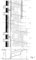
- Fig. 1 shows a refractory wall structure in accordance with the invention in a general embodiment in different stages of wear together with the associated temperature curve.
- Fig. 2 shows as example of the invention a refractory wall structure for a hearth of a blast furnace.
- Fig. 3 shows as example of the invention a refractory wall structure for a final reduction vessel of a smelting reduction process.
- the refractory wall structure of Fig. 1 comprises a steel outer wall (1), means of cooling in the form of water-cooled, copper stave coolers (2) and a well heat-conducting refractory lining (3), for example of graphite.
- the space between the steel outer wall and the stave coolers (2) is filled up with for example mortar (4).
- T process indicates the process temperature
- T cool indicates the reference temperature of the cooling. The figure shows that a considerable fall in temperature occurs across the gap (5) between stave coolers (2) and refractory lining (3) as a result of the high heat resistance of gap (5).
- the situation after the furnace has been in operation for some time is indicated by B.
- the refractory lining (3) is partly worn away as a result of the high temperature and the corrosive conditions. In particular slag containing FeO is especially corrosive.
- T B indicates the temperature curve.
- the total heat transmission resistance of the wall structure has reduced, and the heat flow density has increased through the wall structure. This results in a steeper temperature curve across the residual thickness of refractory lining (3) and a greater temperature drop across gap (5). If the process of wear is allowed to continue then refractory lining (3) becomes further consumed and the risk of breakthrough increases.
- T C indicates the situation with a metallic filling (6) in gap (5) which filling has been molten and therefrom continues to maintain a good thermal contact with the gap walls.
- the filling is a low melting point metal such as for example a tin alloy.
- T C shows that, as a result of the low heat resistance of the filling, the temperature drop across gap (5) is much less.
- the temperature of refractory lining (3) falls so that a slag layer (7) can solidify, which of itself does not conduct heat well, so that a big temperature drop occurs across it, but which protects the residual thickness of refractory lining (3) from further wear.
- Filling (6) can be cast into gap (5) during assembly of the refractory wall structure or be applied there as a film which in situation B will melt.
- Fig. 2 shows the invention applied to the hearth of a blast furnace.
- Jacket (1) is cooled on the outside by means of spray-cooling (2).
- refractory lining (3) consists of two layers, namely layer (3') of graphite and a layer (3'') of semi-graphite.
- a ramming compound of graphite is applied in gap (5) between layers (3') and (3'').
- Situations A and B are analogous to that of Fig. 1.
- situation 3 a considerable part of inner coating layer (3'') has worn away and a considerable temperature drop is occurring across gap (5).
- the figure shows how in situation B the wall structure is repaired after the start of the operation and during operation.
- ducts (8) are drilled through jacket (1), mortar layer (4) and refractory lining layer (3'), which ducts (8) extend into or past gap (5) between lining layers (3') and (3'').
- drilling cannot take place during the production of pig iron because the furnace is under pressure. Therefore the holes are drilled during operation but during a so-called standstill or maintenance stop whereby the production of pig iron is interrupted and whereby the hot blast is switched off and the pressure falls out.
- the ducts can already be made wholly or partly during assembly of the refractory wall structure.
- pellets (9) of a metal with a melting point in the vicinity of the instantaneous temperature at the gap are introduced into the holes. Once the ducts have been drilled this temperature may be measured and the metal selected accordingly.
- the metal can be an alloy of aluminium or copper.
- pellets (9) melt the metal runs into gap (5). The reduced heat resistance of gap (5) makes the temperature drop fall across gap (5), and the temperature of the outer lining layer (3'') falls. Filling (6) solidifies and slag layer (7) can solidify and build up.
- pellets (9) can also be placed in suitable places in the refractory wall structure prior to the operation of the blast furnace. If pellets are placed through such ducts as (8) or similar then these ducts may of course be filled in and sealed (possibly temporarily) after the pellets have been placed.
- the ducts (8) can be provided with nipples (not shown) on the outside of the jacket (1) to which a pressure pipe is connected, through which a pumpable mass containing the metal can be pressed into the ducts (8). The mass then spreads over the gaps in the refractory wall structure and following melting etc. forms heat bridges over the gaps. Contrary to drilling pumping can take place at a furnace under pressure.
- Fig. 3 shows an invention applied to a final reduction vessel for a smelting reduction process, for example of the deep slag type such as for example the Cyclone Converter Furnace (CCF) process.
- the thermal loading here is especially high. Consequently in Fig. 3 not only are stave coolers (2) used, but also water-cooled copper sills (10) which extend into the refractory lining and which serve to improve the heat contact between the refractory lining and the means of cooling (2), (10).
- Refractory lining (3) consists of at least a layer (3') of graphite.
- the means of cooling (2), (10) limit the possibilities of applying pellets afterwards, that is to say during operation.
- pellets (9) during the assembly of the refractory wall structure into suitable cavities (11) in the refractory wall structure which pellets fill gap (5) as they melt on commissioning, or once refractory lining (3) has partly worn away.
- the cavities may also be made for example directly above sills (10).
- sills (10) There is also the possibility to let recesses into the stave coolers through which a duct can be drilled during operation.
- a low heat resistance can, however, also be obtained later during the operation.
Landscapes
- Engineering & Computer Science (AREA)
- Chemical & Material Sciences (AREA)
- Mechanical Engineering (AREA)
- Materials Engineering (AREA)
- Metallurgy (AREA)
- Organic Chemistry (AREA)
- Manufacturing & Machinery (AREA)
- General Engineering & Computer Science (AREA)
- Furnace Housings, Linings, Walls, And Ceilings (AREA)
- Blast Furnaces (AREA)
- Building Environments (AREA)
- Carbon Steel Or Casting Steel Manufacturing (AREA)
- Turbine Rotor Nozzle Sealing (AREA)
Claims (18)
- Feuerfeste Wandstruktur für einen Ofen, insbesondere für einen metallurgischen Ofen, wie beispielsweise einen Hochofen mit einer hohen Prozeßtemperatur während des Betriebs, welche Wandstruktur einer hohen thermischen Belastung ausgesetzt ist, mitworin die feuerfeste Wandstruktur einen Spalt (5) hat und der Spalt Spaltwände hat, wobei der Spalt sich im wesentlichen parallel zu der Außenwand aus Stahl erstreckt, und die Wandstruktur auch eine permanente, gut wärmeleitende metallische Füllung (6) in dem Spalt in der feuerfesten Wandstruktur umfaßt, welche Füllung in dem Spalt (5) geschmolzen worden ist und dann nach der Verfestigung in thermischem Kontakt mit den Spaltwänden steht und einen niedrigen Wärmewiderstand über den Spalt (5) bildet.einer Außenwand (1) aus Stahl,einer feuerfesten Auskleidung (3) an der Innenseite der Außenwandung, welche aus einer oder mehreren Schichten aus einem gut wärmeleitenden Material besteht, undMitteln zum Kühlen (2) der feuerfesten Wandstruktur,
- Feuerfeste Wandstruktur nach Anspruch 1, dadurch gekennzeichnet, daß sie eine Schicht (7) hat, die auf der Innenseite verfestigt ist.
- Feuerfeste Wandstruktur nach den Ansprüchen 1 und 2, dadurch gekennzeichnet, daß der Spalt (5) ein Spalt in der feuerfesten Auskleidung (3) ist.
- Feuerfeste Wandstruktur nach den Ansprüchen 1 bis 3, dadurch gekennzeichnet, daß der Spalt (5) ein Spalt zwischen der Außenwand (1) aus Stahl und der feuerfesten Auskleidung (3) ist.
- Feuerfeste Wandstruktur nach den Ansprüchen 1 bis 4, dadurch gekennzeichnet, daß die Mittel (2) zum Kühlen der feuerfesten Wandstruktur wassergekühlte Kupferkühlelemente sind, und daß der Spalt (5) ein Spalt zwischen der feuerfesten Auskleidung (3) und einem Kühlelement (2) ist.
- Feuerfeste Wandstruktur nach den Ansprüchen 1 bis 5, dadurch gekennzeichnet, daß die metallische Füllung eine Schmelztemperatur hat, die niedriger als die Prozeßtemperatur ist.
- Feuerfeste Wandstruktur nach Anspruch 6, dadurch gekennzeichnet, daß die Schmelztemperatur der Füllung höher als 200°C ist.
- Feuerfeste Wandstruktur nach den Ansprüchen 6 und 7, dadurch gekennzeichnet, daß die Schmelztemperatur der Füllung niedriger als 1100°C ist.
- Feuerfeste Wandstruktur nach den Ansprüchen 1 bis 8, dadurch gekennzeichnet, daß die Füllung einen Wärmeleitkoeffizienten von über 15 W/m°C hat.
- Feuerfeste Wandstruktur nach den Ansprüchen 1 bis 9, dadurch gekennzeichnet, daß die Füllung aus der Gruppe bestehend aus Zinn, Blei, Zink, Aluminium, Silber, Kupfer, Legierungen aus diesen und Kombinationen von diesen ausgewählt ist.
- Feuerfeste Wandstruktur nach den Ansprüchen 1 bis 10, dadurch gekennzeichnet, daß die Füllung während des Betriebs erhalten wird, indem eine Folie geschmolzen wird, die in dem Spalt während des Zusammenbaus einer feuerfesten Wandstruktur vorgesehen worden ist.
- Feuerfeste Wandstruktur nach den Ansprüchen 1 bis 10, dadurch gekennzeichnet, daß die Füllung in geschmolzenem Zustand in den Spalt während des Zusammenbaus der feuerfesten Wandstruktur gegossen wird.
- Feuerfeste Wandstruktur nach den Ansprüchen 1 bis 10, dadurch gekennzeichnet, daß die Füllung während des Betriebs erhalten wird, indem Metall geschmolzen wird, welches in den Spalt in der Form einer Masse, die Metallpartikel enthält, während des Zusammenbaus der feuerfesten Wandstruktur eingebracht wird.
- Feuerfeste Wandstruktur nach den Ansprüchen 1 bis 10, dadurch gekennzeichnet, daß die Füllung während des Betriebs erhalten wird, indem Metall in der Form von einem oder mehreren Pellets (9), die in eine oder mehrere Kavitäten in der feuerfesten Wandstruktur vor oder nach der Inbetriebnahme des Ofens eingebracht werden, geschmolzen wird.
- Feuerfeste Wandstruktur nach den Ansprüchen 1 bis 10, dadurch gekennzeichnet, daß die Füllung während des Betriebs erhalten wird, indem Metall geschmolzen wird, das in der Form von einer pumpbaren Masse, welche das Metall enthält, in die feuerfeste Wandstruktur durch eine Leitung (8) eingebracht wird.
- Feuerfeste Wandstruktur nach Anspruch 15, dadurch gekennzeichnet, daß die pumpbare Masse auch ein Ölprodukt wie Teer oder Pech oder einen aushärtbaren Kunststoff enthält.
- Feuerfeste Wandstruktur nach den Ansprüchen 15 und 16, dadurch gekennzeichnet, daß die pumpbare Masse auch Graphit enthält.
- Feuerfeste Wandstruktur nach den Ansprüchen 1 bis 10, in welcher die Mittel zum Kühlen der feuerfesten Wandstruktur aus wassergekühlten Kupferkühlelementen bestehen, dadurch gekennzeichnet, daß während des Zusammenbaus der feuerfesten Wandstruktur Kühlelemente verwendet werden, die wenigstens teilweise mit einer Beschichtung mit der Substanz der metallischen Füllung versehen worden sind.
Applications Claiming Priority (7)
| Application Number | Priority Date | Filing Date | Title |
|---|---|---|---|
| NL1006169A NL1006169C2 (nl) | 1997-05-30 | 1997-05-30 | Vuurvaste wandconstructie. |
| NL1006169 | 1997-05-30 | ||
| NL1006693A NL1006693C1 (nl) | 1997-07-31 | 1997-07-31 | Vuurvaste wandconstructie. |
| NL1006693 | 1997-07-31 | ||
| NL1006738 | 1997-08-08 | ||
| NL1006738A NL1006738C1 (nl) | 1997-08-08 | 1997-08-08 | Vuurvaste wandconstructie. |
| PCT/EP1998/003194 WO1998054367A1 (en) | 1997-05-30 | 1998-05-28 | Refractory wall structure |
Publications (2)
| Publication Number | Publication Date |
|---|---|
| EP0996747A1 EP0996747A1 (de) | 2000-05-03 |
| EP0996747B1 true EP0996747B1 (de) | 2002-06-12 |
Family
ID=27351156
Family Applications (1)
| Application Number | Title | Priority Date | Filing Date |
|---|---|---|---|
| EP98936294A Expired - Lifetime EP0996747B1 (de) | 1997-05-30 | 1998-05-28 | Feuerfeste mauerstruktur |
Country Status (14)
| Country | Link |
|---|---|
| US (1) | US6234790B1 (de) |
| EP (1) | EP0996747B1 (de) |
| CN (1) | CN1075114C (de) |
| AT (1) | ATE219155T1 (de) |
| AU (1) | AU719587B2 (de) |
| CA (1) | CA2292529C (de) |
| DE (1) | DE69806009T2 (de) |
| ES (1) | ES2178239T3 (de) |
| ID (1) | ID23417A (de) |
| MY (1) | MY141390A (de) |
| RU (1) | RU2175982C2 (de) |
| TW (1) | TW377396B (de) |
| UA (1) | UA41489C2 (de) |
| WO (1) | WO1998054367A1 (de) |
Families Citing this family (13)
| Publication number | Priority date | Publication date | Assignee | Title |
|---|---|---|---|---|
| NL1008625C2 (nl) * | 1998-03-18 | 1999-09-21 | Hoogovens Staal Bv | Wandconstructie voor een metallurgisch vat en hoogoven voorzien van een dergelijke wandconstructie en metalen balken ten gebruike daarbij. |
| DE59903399D1 (de) | 1998-03-19 | 2002-12-19 | Siemens Ag | Wandsegment für einen brennraum sowie brennraum |
| US6374563B1 (en) * | 1999-12-14 | 2002-04-23 | Mobil Oil Corporation | Anchoring system for ceramic lining tile |
| FI112534B (fi) * | 2000-03-21 | 2003-12-15 | Outokumpu Oy | Menetelmä jäähdytyselementin valmistamiseksi ja jäähdytyselementti |
| EP1443119A1 (de) * | 2003-01-29 | 2004-08-04 | VAI Industries (UK) Ltd. | Plattenkühler für metallurgische Schachtöfen |
| NL1027062C1 (nl) * | 2004-06-11 | 2005-12-14 | Press Brick System B V | Bouwsysteem voor het bouwen van vlakke structuren. |
| CN102206516A (zh) | 2010-03-29 | 2011-10-05 | 通用电气公司 | 耐火墙及气化装置和方法 |
| CN103233090B (zh) * | 2013-05-30 | 2014-12-10 | 河北天宇高科冶金铸造有限公司 | 点阵式镶砖冷却壁及其制备工艺 |
| RU2555697C2 (ru) * | 2013-10-15 | 2015-07-10 | Общество С Ограниченной Ответственностью "Медногорский Медно-Серный Комбинат" | Футеровка стенки металлургической печи |
| CN108613554B (zh) * | 2013-12-20 | 2020-02-07 | 魁北克9282-3087公司(加钛顾问公司) | 用于冶金炉的炉盖 |
| KR102545826B1 (ko) * | 2016-02-18 | 2023-06-20 | 해치 리미티드 | 야금로를 위한 냉각 요소 및 그 제조 방법 |
| CN108487507B (zh) * | 2018-04-02 | 2023-08-01 | 浙江省二建建设集团有限公司 | 发电厂用组合式隔热墙及其施工方法 |
| CN110714107A (zh) * | 2019-12-05 | 2020-01-21 | 中冶华天南京工程技术有限公司 | 一种新型冷却壁 |
Family Cites Families (12)
| Publication number | Priority date | Publication date | Assignee | Title |
|---|---|---|---|---|
| DE1944415B2 (de) * | 1969-09-02 | 1972-01-27 | Didier Werke AG, 6200 Wiesbaden | Gebrannter feuerfester formkoerper mit metallischer einlage |
| NL168612C (nl) * | 1975-09-17 | 1982-04-16 | Estel Hoogovens Bv | Schachtoven met een vuurvaste bekleding welke vrije koolstof bevat. |
| IN149308B (de) * | 1977-04-21 | 1981-10-17 | Thyssen Ag | |
| SU779387A1 (ru) * | 1977-10-14 | 1980-11-15 | Днепропетровский Ордена Ленина Металлургический Завод Им. Петровского | Доменна печь |
| SU840114A1 (ru) * | 1978-03-06 | 1981-06-23 | Guz Viktor S | Холодильник металлургическойшАХТНОй пЕчи |
| DE7820149U1 (de) * | 1978-06-27 | 1980-04-03 | Bbc Ag Brown, Boveri & Cie, Baden, Aargau (Schweiz) | Kessel eines lichtbogenofens |
| FR2437447A1 (fr) * | 1978-09-29 | 1980-04-25 | Inst Ochistke T | Dispositif pour l'etancheification des jeux entre les plaques refrigerantes d'un haut fourneau |
| FR2560215B1 (fr) * | 1984-01-18 | 1989-01-06 | Usinor | Perfectionnement aux enveloppes de cowpers ou appareils analogues |
| FR2558173A1 (fr) * | 1984-01-18 | 1985-07-19 | Usinor | Enveloppe de cowper et son procede de fabrication |
| JPS6169908A (ja) * | 1984-09-14 | 1986-04-10 | Sumitomo Metal Ind Ltd | 高炉炉壁補修方法 |
| AUPM393094A0 (en) * | 1994-02-16 | 1994-03-10 | University Of Melbourne, The | Internal refractory cooler |
| RU2064504C1 (ru) * | 1994-08-15 | 1996-07-27 | Частное предприятие "Домна-92" | Устройство охлаждаемой шахты доменной печи |
-
1998
- 1998-05-28 WO PCT/EP1998/003194 patent/WO1998054367A1/en not_active Ceased
- 1998-05-28 RU RU99128091/02A patent/RU2175982C2/ru not_active IP Right Cessation
- 1998-05-28 MY MYPI98002380A patent/MY141390A/en unknown
- 1998-05-28 AT AT98936294T patent/ATE219155T1/de not_active IP Right Cessation
- 1998-05-28 ID IDW991601A patent/ID23417A/id unknown
- 1998-05-28 US US09/424,778 patent/US6234790B1/en not_active Expired - Fee Related
- 1998-05-28 EP EP98936294A patent/EP0996747B1/de not_active Expired - Lifetime
- 1998-05-28 ES ES98936294T patent/ES2178239T3/es not_active Expired - Lifetime
- 1998-05-28 CA CA002292529A patent/CA2292529C/en not_active Expired - Fee Related
- 1998-05-28 AU AU85354/98A patent/AU719587B2/en not_active Ceased
- 1998-05-28 UA UA99127048A patent/UA41489C2/uk unknown
- 1998-05-28 DE DE69806009T patent/DE69806009T2/de not_active Expired - Fee Related
- 1998-05-28 CN CN98806777A patent/CN1075114C/zh not_active Expired - Fee Related
- 1998-06-12 TW TW087109411A patent/TW377396B/zh active
Also Published As
| Publication number | Publication date |
|---|---|
| EP0996747A1 (de) | 2000-05-03 |
| ID23417A (id) | 2000-04-20 |
| TW377396B (en) | 1999-12-21 |
| UA41489C2 (uk) | 2001-09-17 |
| DE69806009D1 (de) | 2002-07-18 |
| CN1075114C (zh) | 2001-11-21 |
| AU8535498A (en) | 1998-12-30 |
| ATE219155T1 (de) | 2002-06-15 |
| CN1261922A (zh) | 2000-08-02 |
| DE69806009T2 (de) | 2003-09-11 |
| CA2292529A1 (en) | 1998-12-03 |
| AU719587B2 (en) | 2000-05-11 |
| RU2175982C2 (ru) | 2001-11-20 |
| US6234790B1 (en) | 2001-05-22 |
| MY141390A (en) | 2010-04-30 |
| CA2292529C (en) | 2005-04-05 |
| WO1998054367A1 (en) | 1998-12-03 |
| ES2178239T3 (es) | 2002-12-16 |
Similar Documents
| Publication | Publication Date | Title |
|---|---|---|
| EP0996747B1 (de) | Feuerfeste mauerstruktur | |
| CA1266776A (en) | Lining for protecting the interior of a metallurgical vessel and a method for forming said lining | |
| KR100689767B1 (ko) | 로-냉각 시스템 | |
| EP0059960B1 (de) | Plattenkühler | |
| JPH10501877A (ja) | 内部耐火性冷却器 | |
| RU99128091A (ru) | Конструкция стены из огнеупорного кирпича | |
| EP1466021B1 (de) | Kühlplatte für metallurgischen ofen und verfahren zur herstellung solch einer platte | |
| EP0076577B1 (de) | Rinne für Metallschmelzen | |
| SU927103A3 (ru) | Способ изготовлени блочной конструкции печной стенки металлургической печи | |
| JPH08246014A (ja) | 高炉水冷溶滓樋 | |
| JP4064387B2 (ja) | 炉体水冷ジャケット | |
| SK142395A3 (en) | Device for feeding molten metal, particularly cast iron, to a casting machine, and casting installation incorporating same | |
| KR101277112B1 (ko) | 냉각 요소 및 그의 제조 방법 | |
| NO172153B (no) | Ildfast beleggsammensetning i form av en smet- eller sproeytemasse for beskyttelse av foringer i metallurgiske smelteovner, tappe- og stoepeoeser, renner og tappetuter | |
| NL1006738C1 (nl) | Vuurvaste wandconstructie. | |
| NL1006693C1 (nl) | Vuurvaste wandconstructie. | |
| CA2323619C (en) | Wall structure for a metallurgical vessel and blast furnace provided with a wall structure of this nature | |
| US4468780A (en) | Method of lining a steel-making furnace | |
| KR102372663B1 (ko) | 용융로 내화물 구조체 및 이를 구비하는 용융로 | |
| GB1585155A (en) | Arc-furnace lining | |
| AU682578B2 (en) | Internal refractory cooler | |
| SU1156841A1 (ru) | Металлопровод дл лить под низким давлением | |
| JPH06322419A (ja) | ステーブ | |
| Coetzee et al. | Application of UCAR® Chill Kote™ lining to ilmenite smelting | |
| JPS58110981A (ja) | 水冷式耐火炉 |
Legal Events
| Date | Code | Title | Description |
|---|---|---|---|
| PUAI | Public reference made under article 153(3) epc to a published international application that has entered the european phase |
Free format text: ORIGINAL CODE: 0009012 |
|
| 17P | Request for examination filed |
Effective date: 19991230 |
|
| AK | Designated contracting states |
Kind code of ref document: A1 Designated state(s): AT BE DE ES FR GB IT NL |
|
| RAP1 | Party data changed (applicant data changed or rights of an application transferred) |
Owner name: CORUS STAAL BV |
|
| 17Q | First examination report despatched |
Effective date: 20010208 |
|
| GRAG | Despatch of communication of intention to grant |
Free format text: ORIGINAL CODE: EPIDOS AGRA |
|
| GRAG | Despatch of communication of intention to grant |
Free format text: ORIGINAL CODE: EPIDOS AGRA |
|
| GRAG | Despatch of communication of intention to grant |
Free format text: ORIGINAL CODE: EPIDOS AGRA |
|
| GRAH | Despatch of communication of intention to grant a patent |
Free format text: ORIGINAL CODE: EPIDOS IGRA |
|
| GRAH | Despatch of communication of intention to grant a patent |
Free format text: ORIGINAL CODE: EPIDOS IGRA |
|
| GRAA | (expected) grant |
Free format text: ORIGINAL CODE: 0009210 |
|
| AK | Designated contracting states |
Kind code of ref document: B1 Designated state(s): AT BE DE ES FR GB IT NL |
|
| REF | Corresponds to: |
Ref document number: 219155 Country of ref document: AT Date of ref document: 20020615 Kind code of ref document: T |
|
| REG | Reference to a national code |
Ref country code: GB Ref legal event code: FG4D |
|
| REF | Corresponds to: |
Ref document number: 69806009 Country of ref document: DE Date of ref document: 20020718 |
|
| ET | Fr: translation filed | ||
| REG | Reference to a national code |
Ref country code: ES Ref legal event code: FG2A Ref document number: 2178239 Country of ref document: ES Kind code of ref document: T3 |
|
| PLBE | No opposition filed within time limit |
Free format text: ORIGINAL CODE: 0009261 |
|
| STAA | Information on the status of an ep patent application or granted ep patent |
Free format text: STATUS: NO OPPOSITION FILED WITHIN TIME LIMIT |
|
| 26N | No opposition filed |
Effective date: 20030313 |
|
| PGFP | Annual fee paid to national office [announced via postgrant information from national office to epo] |
Ref country code: AT Payment date: 20060406 Year of fee payment: 9 |
|
| PGFP | Annual fee paid to national office [announced via postgrant information from national office to epo] |
Ref country code: FR Payment date: 20060411 Year of fee payment: 9 |
|
| PGFP | Annual fee paid to national office [announced via postgrant information from national office to epo] |
Ref country code: GB Payment date: 20060412 Year of fee payment: 9 |
|
| PGFP | Annual fee paid to national office [announced via postgrant information from national office to epo] |
Ref country code: DE Payment date: 20060419 Year of fee payment: 9 |
|
| PGFP | Annual fee paid to national office [announced via postgrant information from national office to epo] |
Ref country code: ES Payment date: 20060505 Year of fee payment: 9 |
|
| PGFP | Annual fee paid to national office [announced via postgrant information from national office to epo] |
Ref country code: BE Payment date: 20060516 Year of fee payment: 9 |
|
| PGFP | Annual fee paid to national office [announced via postgrant information from national office to epo] |
Ref country code: NL Payment date: 20060531 Year of fee payment: 9 Ref country code: IT Payment date: 20060531 Year of fee payment: 9 |
|
| BERE | Be: lapsed |
Owner name: *CORUS STAAL B.V. Effective date: 20070531 |
|
| GBPC | Gb: european patent ceased through non-payment of renewal fee |
Effective date: 20070528 |
|
| PG25 | Lapsed in a contracting state [announced via postgrant information from national office to epo] |
Ref country code: NL Free format text: LAPSE BECAUSE OF NON-PAYMENT OF DUE FEES Effective date: 20071201 |
|
| NLV4 | Nl: lapsed or anulled due to non-payment of the annual fee |
Effective date: 20071201 |
|
| PG25 | Lapsed in a contracting state [announced via postgrant information from national office to epo] |
Ref country code: AT Free format text: LAPSE BECAUSE OF NON-PAYMENT OF DUE FEES Effective date: 20070528 |
|
| REG | Reference to a national code |
Ref country code: FR Ref legal event code: ST Effective date: 20080131 |
|
| PG25 | Lapsed in a contracting state [announced via postgrant information from national office to epo] |
Ref country code: BE Free format text: LAPSE BECAUSE OF NON-PAYMENT OF DUE FEES Effective date: 20070531 |
|
| PG25 | Lapsed in a contracting state [announced via postgrant information from national office to epo] |
Ref country code: DE Free format text: LAPSE BECAUSE OF NON-PAYMENT OF DUE FEES Effective date: 20071201 |
|
| PG25 | Lapsed in a contracting state [announced via postgrant information from national office to epo] |
Ref country code: GB Free format text: LAPSE BECAUSE OF NON-PAYMENT OF DUE FEES Effective date: 20070528 |
|
| PG25 | Lapsed in a contracting state [announced via postgrant information from national office to epo] |
Ref country code: FR Free format text: LAPSE BECAUSE OF NON-PAYMENT OF DUE FEES Effective date: 20070531 |
|
| REG | Reference to a national code |
Ref country code: ES Ref legal event code: FD2A Effective date: 20070529 |
|
| PG25 | Lapsed in a contracting state [announced via postgrant information from national office to epo] |
Ref country code: ES Free format text: LAPSE BECAUSE OF NON-PAYMENT OF DUE FEES Effective date: 20070529 |
|
| PG25 | Lapsed in a contracting state [announced via postgrant information from national office to epo] |
Ref country code: IT Free format text: LAPSE BECAUSE OF NON-PAYMENT OF DUE FEES Effective date: 20070528 |