EP0997204B1 - Kühlungstopf mit Höhenvestellbarer Tragplette - Google Patents
Kühlungstopf mit Höhenvestellbarer Tragplette Download PDFInfo
- Publication number
- EP0997204B1 EP0997204B1 EP99308481A EP99308481A EP0997204B1 EP 0997204 B1 EP0997204 B1 EP 0997204B1 EP 99308481 A EP99308481 A EP 99308481A EP 99308481 A EP99308481 A EP 99308481A EP 0997204 B1 EP0997204 B1 EP 0997204B1
- Authority
- EP
- European Patent Office
- Prior art keywords
- shelf
- side wall
- coil
- access openings
- rings
- Prior art date
- Legal status (The legal status is an assumption and is not a legal conclusion. Google has not performed a legal analysis and makes no representation as to the accuracy of the status listed.)
- Expired - Lifetime
Links
Images


Classifications
-
- B—PERFORMING OPERATIONS; TRANSPORTING
- B21—MECHANICAL METAL-WORKING WITHOUT ESSENTIALLY REMOVING MATERIAL; PUNCHING METAL
- B21B—ROLLING OF METAL
- B21B27/00—Rolls, roll alloys or roll fabrication; Lubricating, cooling or heating rolls while in use
-
- B—PERFORMING OPERATIONS; TRANSPORTING
- B21—MECHANICAL METAL-WORKING WITHOUT ESSENTIALLY REMOVING MATERIAL; PUNCHING METAL
- B21C—MANUFACTURE OF METAL SHEETS, WIRE, RODS, TUBES, PROFILES OR LIKE SEMI-MANUFACTURED PRODUCTS OTHERWISE THAN BY ROLLING; AUXILIARY OPERATIONS USED IN CONNECTION WITH METAL-WORKING WITHOUT ESSENTIALLY REMOVING MATERIAL
- B21C47/00—Winding-up, coiling or winding-off metal wire, metal band or other flexible metal material characterised by features relevant to metal processing only
- B21C47/02—Winding-up or coiling
- B21C47/10—Winding-up or coiling by means of a moving guide
- B21C47/14—Winding-up or coiling by means of a moving guide by means of a rotating guide, e.g. laying the material around a stationary reel or drum
Definitions
- This invention relates generally to rolling mills producing hot rolled steel products such as bars, rods and the like, and is concerned in particular to an improvement in the retarded cooling of such products in insulated containers commonly referred to as "pots".
- JP54-043856 discloses a coil-forming system in which the coils are deposited on a separate annular platform which must be provided for each coil receiving pot.
- the primary objective of the present invention is the provision of an improved pot and associated adjustable coil support which operate in concert to maintain the top of the coil being formed in the pot at an optimum substantially constant height. By doing so, ring density and distribution is optimized and maintained substantially constant from the bottom to the top end of the coil, which in turn minimizes coil size while maximizing coil stability.
- a rolling mill comprising a pinch roll unit 10 arranged to direct a hot rolled rod 12 or other like product into an inclined laying head 14 which forms the product into a continuous helical series of rings 16.
- the rings are received on a conveyor 18 on which they are carried forward in an overlapping nonconcentric arrangement towards a reforming station 20. Insulated covers 22 may overlie the conveyor to retard the cooling rate of the rings.
- the rings drop from the conveyor into an insulated portable container commonly referred to as a "pot" 24 where they gather into an upstanding cylindrical coil. As each pot is filled, it is shifted to an adjacent station 26 where the coils are allowed to cool at a retarded rate before eventually being removed from the pots.
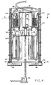
- a pot 24 in accordance with the present invention is shown supported on a roller table 28 at the reforming station 20.
- the pot has a vertically disposed insulated side wall 30 open at its upper and lower ends.
- a frame-like base 32 with a central opening is configured to support the pot on the roller table.
- Truncated somewhat pig shaped segments 34 of a horizontal shelf project inwardly from the interior of the side wall.
- the inner ends of the shelf segments 34 support vertically extending arcuate segments 36 of a central core 38.
- the core segments 26 are connected at their upper ends by a cap 40.
- the core 38 is centrally located and spaced inwardly from the interior of the side wall 30 to define an annular chamber 42 therebetween.
- the shelf segments 34 are circumferentially spaced one from the other to define access openings which communicate with vertical slots between the core segments 36.
- Vertical rails indicated typically at 44 are secured to the interior of the side wall 30.
- the rails project radially inwardly into the annular chamber 42, and as will be explained hereinafter, serve to space the rings gathering in the pot from the interior of the side wall 30, thereby promoting uniform retarded cooling.
- rollers 46 of the roller table are spaced one from the other and configured to define a cross-shaped opening 48, the arms of which are aligned with the access openings between the shelf segments 34.
- An elevator platform 50 is positioned beneath the roller table 28 for vertical adjustment through the cross-shaped opening 48.
- the elevator platform is generally in the shape of a cross, the arms 52 of which are provided with guide rollers 54.
- the crossed arms 52 are aligned with the cross-shaped opening 48 defined by the table rollers 46, as well as with the access openings between the shelf segments 34 and the vertical slots between the core segments 36.
- the elevator platform is vertically adjustable by an appropriate mechanism, one example being a thrust motion rigid chain drive 56 of the type supplied by Serapid USA, Inc. of Troy, Michigan.
- the elevator platform 50 is projected upwardly into the pot 24, with the rollers 54 coacting with selected rails 44 to provide a guiding function. Rings 16 are received through the open top of the pot. The rings are deposited on the raised platform 50 where they accumulate in coil form around the central core 38. The platform 50 is gradually lowered to maintain the top of the growing coil at an optimum level "L", thereby maintaining the drop distance of the rings substantially constant. At the end of the coil forming operation, the platform descends below the roller table, and in so doing transfers the coil into the shelf segments 34.
- the upper end of the central core 38 is spaced below the upper rim of the wall 30 to thereby define an upper recess 58.
- the shelf segments 34 are spaced above the lower rim of the wall 30 to thereby define a lower recess 60.
- insulated top and bottom covers 62, 64 are positioned respectively in the upper and lower recesses 58, 60 to fully enclose the coil within the pot.
Landscapes
- Engineering & Computer Science (AREA)
- Mechanical Engineering (AREA)
- Winding, Rewinding, Material Storage Devices (AREA)
- Metal Rolling (AREA)
- Heat Treatments In General, Especially Conveying And Cooling (AREA)
- Coiling Of Filamentary Materials In General (AREA)
- Cookers (AREA)
- Devices That Are Associated With Refrigeration Equipment (AREA)
Claims (10)
- Vorrichtung zum Aufnehmen einer kontinuierlichen Abfolge von Ringen (16) eines warmgewalzten Produktes (12), wobei die gesagte Vorrichtung umfasst:a) einen transportablen Behälter (24), welcher aufweist:(i) eine vertikal angeordnete zylindrische Seitenwand (30), welche an ihrem oberen und unteren Ende geöffnet ist;(ii) einen Boden (32) an dem unteren Ende der gesagten Seitenwand, welcher derart ausgeführt ist, dass er den gesagten Behälter an einer Bundformungsstation (20) entfembar positioniert;(iii) ein horizontales Bord (34), welches nach innen ausgehend von der Innenseite der gesagten Seitenwand aus hervorsteht; und(iv) ein mittlerer Kern (38), welcher durch das gesagte Bord getragen wird, wobei der Kern mit Abstand zu der Innenseite der gesagten Seitenwand angeordnet ist, um eine ringförmige Kammer (42) dort zwischen auszubilden, wobei das gesagte Bord Zugriffsöffnungen in sich aufweist, welche in Verbindung mit der gesagten Kammer stehen;b) eine Hebebühne (50) an der gesagten Bundformungsstation; wobei die gesagte Bühne Tragelemente (52) aufweist, welche derart ausgeführt und angeordnet sind, dass sie durch die Zugriffsöffnungen in dem gesagten Bord hindurchtreten;c) ein Mittel (56) zum vertikalen Einstellen der gesagten Hebebühne, um die gesagten Tragelemente durch die Zugriffsöffnungen in dem gesagten Bord zwischen angehobenen Positionen im Betrieb und einer Position außerhalb des Betriebs unterhalb des gesagten Bords zu bewegen, dadurch gekennzeichnet, dass in den angehobenen Positionen im Betrieb die gesagten Tragelemente in die gesagte Kammer hineinragen, um direkt einen Bund zu tragen, welcher durch die Aufnahme der gesagten Ringe durch das gesagte obere Ende geformt wird, und dass die Bewegung in die gesagte Position außerhalb des Betriebs unterhalb des gesagten Bords dazu führt, dass das gesagte direkte Tragen des gesagten Bundes von den gesagten Tragelementen auf das gesagte Bord übertragen wird.
- Vorrichtung, wie sie in Anspruch 1 beansprucht wird, wobei das gesagte Bord aus in Umfangsrichtung mit Abstand zueinander angeordneten Segmenten (34) zusammengesetzt ist, welche die gesagten Zugriffsöffnungen zwischen sich ausbilden.
- Vorrichtung, wie sie in Anspruch 1 oder 2 beansprucht wird, wobei der gesagte Kern zueinander mit Abstand angeordnete Rippen (36) umfasst, welche durch die gesagten Bordsegmente getragen werden und sich vertikal von diesen aus erstrecken.
- Vorrichtung, wie sie in Anspruch 3 beansprucht wird, wobei die gesagten Rippen an ihren oberen Enden durch einen Deckel (40) untereinander verbunden sind.
- Vorrichtung, wie sie in Anspruch 4 beansprucht wird, wobei der gesagte Deckel mit Abstand unterhalb der oberen Kante der gesagten Seitenwand angeordnet ist, um eine obere Aussparung (58) zu bilden, welche derart ausgeführt und angeordnet ist, dass sie entfembar eine isolierte obere Abdeckung aufnimmt.
- Vorrichtung, wie sie in einem der vorhergehenden Ansprüche beansprucht wird, wobei das gesagte Bord mit Abstand oberhalb des unteren Endes der gesagten Seitenwand angeordnet ist, um eine untere Aussparung (60) zu bilden, welche derart ausgeführt und angeordnet ist, dass sie eine isolierte untere Abdeckung entfembar aufnimmt.
- Vorrichtung, wie sie in einem der vorhergehenden Ansprüche beansprucht wird, wobei der gesagte Boden durch einen Rollenförderer (18) an der gesagten Umformstation getragen wird, wobei der gesagte Rollenförderer Rollen aufweist, welche derart ausgeführt und angeordnet sind, dass sie Öffnungen (48) zwischen sich ausbilden, welche mit den Zugriffsöffnungen in dem gesagten Bord fluchten.
- Vorrichtung, wie sie in einem der vorhergehenden Ansprüche beansprucht wird, ferner umfassend Schienenelemente (44), welche von der Innenseite der gesagten Seitenwand aus in die gesagte Kammer hinein hervorstehen, wobei die gesagten Schienenelemente derart ausgeführt und angeordnet sind, dass sie einen Raum zwischen der Außenseite des gesagten Bundes und der Innenseite der gesagten Seitenwand ausbilden.
- Vorrichtung, wie sie in Anspruch 8 beansprucht wird, wobei die gesagte Hebebühne während ihrer vertikalen Einstellungen durch die gesagten Schienenelemente geführt wird.
- Ein Walzwerk zum Herstellen eines warmgewalzten Produktes in einer gewickelten Form, wobei das gesagte Walzwerk an seinem Lieferende einen Legekonus (14) zum Formen des Produktes in eine Reihe von schraubenförmigen Ringen (16) und einen Förderer zum Transportieren der Ringe zu einer Bundformungsstation (20) aufweist, wobei an der Bundformungsstation eine Vorrichtung gemäß einem der vorhergehenden Ansprüche angeordnet ist.
Applications Claiming Priority (4)
| Application Number | Priority Date | Filing Date | Title |
|---|---|---|---|
| US10627498P | 1998-10-30 | 1998-10-30 | |
| US106274P | 1998-10-30 | ||
| US416658 | 1999-10-12 | ||
| US09/416,658 US6237868B1 (en) | 1998-10-30 | 1999-10-12 | Cooling pot with vertically adjustable coil plate |
Publications (3)
| Publication Number | Publication Date |
|---|---|
| EP0997204A2 EP0997204A2 (de) | 2000-05-03 |
| EP0997204A3 EP0997204A3 (de) | 2001-06-13 |
| EP0997204B1 true EP0997204B1 (de) | 2005-03-02 |
Family
ID=26803497
Family Applications (1)
| Application Number | Title | Priority Date | Filing Date |
|---|---|---|---|
| EP99308481A Expired - Lifetime EP0997204B1 (de) | 1998-10-30 | 1999-10-27 | Kühlungstopf mit Höhenvestellbarer Tragplette |
Country Status (11)
| Country | Link |
|---|---|
| US (1) | US6237868B1 (de) |
| EP (1) | EP0997204B1 (de) |
| JP (1) | JP3091756B2 (de) |
| KR (1) | KR100344382B1 (de) |
| CN (1) | CN1096318C (de) |
| AT (1) | ATE289885T1 (de) |
| BR (1) | BR9904981B1 (de) |
| CA (1) | CA2286388C (de) |
| DE (1) | DE69923908T2 (de) |
| ES (1) | ES2237891T3 (de) |
| TW (1) | TW450846B (de) |
Families Citing this family (6)
| Publication number | Priority date | Publication date | Assignee | Title |
|---|---|---|---|---|
| GB0822611D0 (en) * | 2008-12-11 | 2009-01-21 | Acergy Norway As | Carousel for flexible product |
| KR101353855B1 (ko) * | 2011-12-20 | 2014-01-21 | 주식회사 포스코 | 선재코일 균일냉각장치 |
| GB2501752B (en) | 2012-05-04 | 2015-01-28 | Siemens Vai Metals Tech Gmbh | Coil forming device |
| WO2017123374A1 (en) * | 2016-01-11 | 2017-07-20 | Primetals Technologies USA LLC | Rolling mill pouring reel |
| CN110605351B (zh) * | 2019-09-30 | 2024-12-24 | 天津理工大学 | 航天用超大型环件轧制过程中温度补偿的方法及专用装置 |
| US20220219215A1 (en) | 2021-01-11 | 2022-07-14 | Primetals Technologies USA LLC | Automated rod coil cutting station |
Citations (1)
| Publication number | Priority date | Publication date | Assignee | Title |
|---|---|---|---|---|
| FR1526997A (fr) * | 1966-02-17 | 1968-05-31 | Schloemann Ag | Procédé pour former des spires individuelles de fil |
Family Cites Families (13)
| Publication number | Priority date | Publication date | Assignee | Title |
|---|---|---|---|---|
| US2957640A (en) * | 1958-02-24 | 1960-10-25 | Coulter & Mckenzie Machine Co | Wire coiling machine |
| US2929493A (en) * | 1958-08-14 | 1960-03-22 | Western Electric Co | Apparatus for advancing strands |
| US3088690A (en) * | 1959-06-02 | 1963-05-07 | Delore Sa Geoffroy | Wire coiling apparatus |
| US3014577A (en) * | 1960-06-03 | 1961-12-26 | Syncro Mach Co | Container for coils of wire |
| FR2097705A5 (de) * | 1970-07-20 | 1972-03-03 | Bekaert Sa Nv | |
| IT982128B (it) * | 1973-03-15 | 1974-10-21 | Crotti R | Dispositivo per la raccolta corret ta di focacce di filo e o filato in particolare di focacce con buco centrale |
| JPS5443856A (en) * | 1977-09-14 | 1979-04-06 | Kobe Steel Ltd | Method and apparatus for coiling wire |
| JPS57170352A (en) * | 1981-04-13 | 1982-10-20 | Nippon Steel Corp | Method and apparatus for bundling ring-shaped wire rod |
| JPH0195816A (ja) * | 1987-10-07 | 1989-04-13 | Daido Steel Co Ltd | 熱間圧延線材の集束装置 |
| DE4029494A1 (de) * | 1990-09-18 | 1992-03-19 | Hasenclever Maschf Sms | Drahthaspel mit drehender wickeltrommel |
| EP0704257B1 (de) * | 1994-09-30 | 2000-03-15 | DANIELI & C. OFFICINE MECCANICHE S.p.A. | Wickelanlage für Eisen- und Stahlprodukte |
| US5501410A (en) * | 1995-01-27 | 1996-03-26 | Morgan Construction Company | Coil reforming chamber with auxiliary coil plate |
| CA2210042A1 (en) * | 1996-07-23 | 1998-01-23 | Edward Ewart Lafleur | Compatible and miscible copolymer compositions |
-
1999
- 1999-10-12 US US09/416,658 patent/US6237868B1/en not_active Expired - Lifetime
- 1999-10-14 CA CA002286388A patent/CA2286388C/en not_active Expired - Fee Related
- 1999-10-26 TW TW088118512A patent/TW450846B/zh not_active IP Right Cessation
- 1999-10-27 AT AT99308481T patent/ATE289885T1/de active
- 1999-10-27 DE DE69923908T patent/DE69923908T2/de not_active Expired - Lifetime
- 1999-10-27 EP EP99308481A patent/EP0997204B1/de not_active Expired - Lifetime
- 1999-10-27 ES ES99308481T patent/ES2237891T3/es not_active Expired - Lifetime
- 1999-10-28 JP JP11306616A patent/JP3091756B2/ja not_active Expired - Fee Related
- 1999-10-29 CN CN99123288A patent/CN1096318C/zh not_active Expired - Fee Related
- 1999-10-29 KR KR1019990047360A patent/KR100344382B1/ko not_active Expired - Fee Related
- 1999-10-29 BR BRPI9904981-3A patent/BR9904981B1/pt not_active IP Right Cessation
Patent Citations (1)
| Publication number | Priority date | Publication date | Assignee | Title |
|---|---|---|---|---|
| FR1526997A (fr) * | 1966-02-17 | 1968-05-31 | Schloemann Ag | Procédé pour former des spires individuelles de fil |
Also Published As
| Publication number | Publication date |
|---|---|
| US6237868B1 (en) | 2001-05-29 |
| TW450846B (en) | 2001-08-21 |
| CN1260252A (zh) | 2000-07-19 |
| CA2286388A1 (en) | 2000-04-30 |
| JP2000135514A (ja) | 2000-05-16 |
| EP0997204A2 (de) | 2000-05-03 |
| KR100344382B1 (ko) | 2002-07-24 |
| DE69923908D1 (de) | 2005-04-07 |
| DE69923908T2 (de) | 2006-04-06 |
| ES2237891T3 (es) | 2005-08-01 |
| BR9904981A (pt) | 2000-08-15 |
| BR9904981B1 (pt) | 2009-08-11 |
| ATE289885T1 (de) | 2005-03-15 |
| CN1096318C (zh) | 2002-12-18 |
| KR20000029403A (ko) | 2000-05-25 |
| EP0997204A3 (de) | 2001-06-13 |
| CA2286388C (en) | 2004-01-06 |
| JP3091756B2 (ja) | 2000-09-25 |
Similar Documents
| Publication | Publication Date | Title |
|---|---|---|
| EP0997204B1 (de) | Kühlungstopf mit Höhenvestellbarer Tragplette | |
| EP0583099B1 (de) | Schleifenleitvorrichtung für Reformingstation | |
| US10773288B2 (en) | Reform tub iris to also include coil shear | |
| US5501410A (en) | Coil reforming chamber with auxiliary coil plate | |
| EP0916422A2 (de) | Verfahren und Vorrichtung zum Formen von Windungen | |
| MXPA99010024A (es) | Olla de enfriamiento con plancha de bobina ajustable verticalmente | |
| RU2203756C2 (ru) | Охладительный контейнер с вертикально перемещаемой платформой для бунта | |
| CA2222353A1 (en) | Stem coil pallet for making half weight coils | |
| CN107380503A (zh) | 装配力自动调节的包装圆筒封盖组装设备 | |
| EP0992592A2 (de) | System zur retardierten Kühlung mit körnigem Wärmedämmaterial | |
| EP3402615B1 (de) | Sammeltrommel für walzwerk | |
| JPH0649385Y2 (ja) | 缶蓋供給装置の供給位置調整装置 | |
| IT1267297B1 (it) | Procedimento di bobinatura per prodotti siderurgici e relativo dispositivo |
Legal Events
| Date | Code | Title | Description |
|---|---|---|---|
| PUAI | Public reference made under article 153(3) epc to a published international application that has entered the european phase |
Free format text: ORIGINAL CODE: 0009012 |
|
| AK | Designated contracting states |
Kind code of ref document: A2 Designated state(s): AT BE CH CY DE DK ES FI FR GB GR IE IT LI LU MC NL PT SE |
|
| AX | Request for extension of the european patent |
Free format text: AL;LT;LV;MK;RO;SI |
|
| PUAL | Search report despatched |
Free format text: ORIGINAL CODE: 0009013 |
|
| AK | Designated contracting states |
Kind code of ref document: A3 Designated state(s): AT BE CH CY DE DK ES FI FR GB GR IE IT LI LU MC NL PT SE |
|
| AX | Request for extension of the european patent |
Free format text: AL;LT;LV;MK;RO;SI |
|
| 17P | Request for examination filed |
Effective date: 20011127 |
|
| AKX | Designation fees paid |
Free format text: AT BE CH CY DE DK ES FI FR GB GR IE IT LI LU MC NL PT SE |
|
| 17Q | First examination report despatched |
Effective date: 20030324 |
|
| GRAP | Despatch of communication of intention to grant a patent |
Free format text: ORIGINAL CODE: EPIDOSNIGR1 |
|
| GRAS | Grant fee paid |
Free format text: ORIGINAL CODE: EPIDOSNIGR3 |
|
| GRAP | Despatch of communication of intention to grant a patent |
Free format text: ORIGINAL CODE: EPIDOSNIGR1 |
|
| GRAA | (expected) grant |
Free format text: ORIGINAL CODE: 0009210 |
|
| AK | Designated contracting states |
Kind code of ref document: B1 Designated state(s): AT BE CH CY DE DK ES FI FR GB GR IE IT LI LU MC NL PT SE |
|
| PG25 | Lapsed in a contracting state [announced via postgrant information from national office to epo] |
Ref country code: NL Free format text: LAPSE BECAUSE OF FAILURE TO SUBMIT A TRANSLATION OF THE DESCRIPTION OR TO PAY THE FEE WITHIN THE PRESCRIBED TIME-LIMIT Effective date: 20050302 Ref country code: LI Free format text: LAPSE BECAUSE OF FAILURE TO SUBMIT A TRANSLATION OF THE DESCRIPTION OR TO PAY THE FEE WITHIN THE PRESCRIBED TIME-LIMIT Effective date: 20050302 Ref country code: FI Free format text: LAPSE BECAUSE OF FAILURE TO SUBMIT A TRANSLATION OF THE DESCRIPTION OR TO PAY THE FEE WITHIN THE PRESCRIBED TIME-LIMIT Effective date: 20050302 Ref country code: CH Free format text: LAPSE BECAUSE OF FAILURE TO SUBMIT A TRANSLATION OF THE DESCRIPTION OR TO PAY THE FEE WITHIN THE PRESCRIBED TIME-LIMIT Effective date: 20050302 Ref country code: BE Free format text: LAPSE BECAUSE OF FAILURE TO SUBMIT A TRANSLATION OF THE DESCRIPTION OR TO PAY THE FEE WITHIN THE PRESCRIBED TIME-LIMIT Effective date: 20050302 |
|
| REG | Reference to a national code |
Ref country code: GB Ref legal event code: FG4D |
|
| REG | Reference to a national code |
Ref country code: CH Ref legal event code: EP |
|
| REG | Reference to a national code |
Ref country code: SE Ref legal event code: TRGR |
|
| REG | Reference to a national code |
Ref country code: IE Ref legal event code: FG4D |
|
| REF | Corresponds to: |
Ref document number: 69923908 Country of ref document: DE Date of ref document: 20050407 Kind code of ref document: P |
|
| PG25 | Lapsed in a contracting state [announced via postgrant information from national office to epo] |
Ref country code: GR Free format text: LAPSE BECAUSE OF FAILURE TO SUBMIT A TRANSLATION OF THE DESCRIPTION OR TO PAY THE FEE WITHIN THE PRESCRIBED TIME-LIMIT Effective date: 20050602 Ref country code: DK Free format text: LAPSE BECAUSE OF FAILURE TO SUBMIT A TRANSLATION OF THE DESCRIPTION OR TO PAY THE FEE WITHIN THE PRESCRIBED TIME-LIMIT Effective date: 20050602 |
|
| REG | Reference to a national code |
Ref country code: ES Ref legal event code: FG2A Ref document number: 2237891 Country of ref document: ES Kind code of ref document: T3 |
|
| PG25 | Lapsed in a contracting state [announced via postgrant information from national office to epo] |
Ref country code: PT Free format text: LAPSE BECAUSE OF FAILURE TO SUBMIT A TRANSLATION OF THE DESCRIPTION OR TO PAY THE FEE WITHIN THE PRESCRIBED TIME-LIMIT Effective date: 20050817 |
|
| NLV1 | Nl: lapsed or annulled due to failure to fulfill the requirements of art. 29p and 29m of the patents act | ||
| REG | Reference to a national code |
Ref country code: CH Ref legal event code: PL |
|
| PG25 | Lapsed in a contracting state [announced via postgrant information from national office to epo] |
Ref country code: CY Free format text: LAPSE BECAUSE OF FAILURE TO SUBMIT A TRANSLATION OF THE DESCRIPTION OR TO PAY THE FEE WITHIN THE PRESCRIBED TIME-LIMIT Effective date: 20051027 |
|
| PG25 | Lapsed in a contracting state [announced via postgrant information from national office to epo] |
Ref country code: MC Free format text: LAPSE BECAUSE OF NON-PAYMENT OF DUE FEES Effective date: 20051031 Ref country code: LU Free format text: LAPSE BECAUSE OF NON-PAYMENT OF DUE FEES Effective date: 20051031 |
|
| PLBE | No opposition filed within time limit |
Free format text: ORIGINAL CODE: 0009261 |
|
| STAA | Information on the status of an ep patent application or granted ep patent |
Free format text: STATUS: NO OPPOSITION FILED WITHIN TIME LIMIT |
|
| 26N | No opposition filed |
Effective date: 20051205 |
|
| ET | Fr: translation filed | ||
| REG | Reference to a national code |
Ref country code: GB Ref legal event code: 732E Free format text: REGISTERED BETWEEN 20110310 AND 20110316 |
|
| REG | Reference to a national code |
Ref country code: DE Ref legal event code: R081 Ref document number: 69923908 Country of ref document: DE Owner name: SIEMENS INDUSTRY, INC. (N. D. GES. D. STAATES , US Free format text: FORMER OWNER: MORGAN CONSTRUCTION CO., WORCESTER, MASS., US Effective date: 20110209 |
|
| REG | Reference to a national code |
Ref country code: ES Ref legal event code: PC2A Owner name: SIEMENS INDUSTRY, INC. Effective date: 20110428 |
|
| REG | Reference to a national code |
Ref country code: FR Ref legal event code: TP |
|
| PGFP | Annual fee paid to national office [announced via postgrant information from national office to epo] |
Ref country code: FR Payment date: 20121031 Year of fee payment: 14 Ref country code: IE Payment date: 20121019 Year of fee payment: 14 |
|
| PGFP | Annual fee paid to national office [announced via postgrant information from national office to epo] |
Ref country code: SE Payment date: 20121009 Year of fee payment: 14 Ref country code: ES Payment date: 20121129 Year of fee payment: 14 Ref country code: IT Payment date: 20121030 Year of fee payment: 14 Ref country code: GB Payment date: 20121011 Year of fee payment: 14 |
|
| PGFP | Annual fee paid to national office [announced via postgrant information from national office to epo] |
Ref country code: AT Payment date: 20120912 Year of fee payment: 14 |
|
| PGFP | Annual fee paid to national office [announced via postgrant information from national office to epo] |
Ref country code: DE Payment date: 20121216 Year of fee payment: 14 |
|
| REG | Reference to a national code |
Ref country code: SE Ref legal event code: EUG |
|
| REG | Reference to a national code |
Ref country code: AT Ref legal event code: MM01 Ref document number: 289885 Country of ref document: AT Kind code of ref document: T Effective date: 20131027 |
|
| GBPC | Gb: european patent ceased through non-payment of renewal fee |
Effective date: 20131027 |
|
| REG | Reference to a national code |
Ref country code: DE Ref legal event code: R119 Ref document number: 69923908 Country of ref document: DE Effective date: 20140501 |
|
| REG | Reference to a national code |
Ref country code: IE Ref legal event code: MM4A |
|
| PG25 | Lapsed in a contracting state [announced via postgrant information from national office to epo] |
Ref country code: GB Free format text: LAPSE BECAUSE OF NON-PAYMENT OF DUE FEES Effective date: 20131027 |
|
| REG | Reference to a national code |
Ref country code: FR Ref legal event code: ST Effective date: 20140630 |
|
| PG25 | Lapsed in a contracting state [announced via postgrant information from national office to epo] |
Ref country code: SE Free format text: LAPSE BECAUSE OF NON-PAYMENT OF DUE FEES Effective date: 20131028 Ref country code: IT Free format text: LAPSE BECAUSE OF NON-PAYMENT OF DUE FEES Effective date: 20131027 Ref country code: DE Free format text: LAPSE BECAUSE OF NON-PAYMENT OF DUE FEES Effective date: 20140501 Ref country code: AT Free format text: LAPSE BECAUSE OF NON-PAYMENT OF DUE FEES Effective date: 20131027 Ref country code: FR Free format text: LAPSE BECAUSE OF NON-PAYMENT OF DUE FEES Effective date: 20131031 |
|
| PG25 | Lapsed in a contracting state [announced via postgrant information from national office to epo] |
Ref country code: IE Free format text: LAPSE BECAUSE OF NON-PAYMENT OF DUE FEES Effective date: 20131027 |
|
| REG | Reference to a national code |
Ref country code: ES Ref legal event code: FD2A Effective date: 20150401 |
|
| PG25 | Lapsed in a contracting state [announced via postgrant information from national office to epo] |
Ref country code: ES Free format text: LAPSE BECAUSE OF NON-PAYMENT OF DUE FEES Effective date: 20131028 |