EP0997282A2 - Druckvorrichtung - Google Patents
Druckvorrichtung Download PDFInfo
- Publication number
- EP0997282A2 EP0997282A2 EP99120876A EP99120876A EP0997282A2 EP 0997282 A2 EP0997282 A2 EP 0997282A2 EP 99120876 A EP99120876 A EP 99120876A EP 99120876 A EP99120876 A EP 99120876A EP 0997282 A2 EP0997282 A2 EP 0997282A2
- Authority
- EP
- European Patent Office
- Prior art keywords
- ink
- discharge electrodes
- pigment particles
- electric field
- charged pigment
- Prior art date
- Legal status (The legal status is an assumption and is not a legal conclusion. Google has not performed a legal analysis and makes no representation as to the accuracy of the status listed.)
- Withdrawn
Links
Images









Classifications
-
- B—PERFORMING OPERATIONS; TRANSPORTING
- B41—PRINTING; LINING MACHINES; TYPEWRITERS; STAMPS
- B41J—TYPEWRITERS; SELECTIVE PRINTING MECHANISMS, i.e. MECHANISMS PRINTING OTHERWISE THAN FROM A FORME; CORRECTION OF TYPOGRAPHICAL ERRORS
- B41J2/00—Typewriters or selective printing mechanisms characterised by the printing or marking process for which they are designed
- B41J2/005—Typewriters or selective printing mechanisms characterised by the printing or marking process for which they are designed characterised by bringing liquid or particles selectively into contact with a printing material
- B41J2/01—Ink jet
- B41J2/015—Ink jet characterised by the jet generation process
- B41J2/04—Ink jet characterised by the jet generation process generating single droplets or particles on demand
- B41J2/045—Ink jet characterised by the jet generation process generating single droplets or particles on demand by pressure, e.g. electromechanical transducers
-
- B—PERFORMING OPERATIONS; TRANSPORTING
- B41—PRINTING; LINING MACHINES; TYPEWRITERS; STAMPS
- B41J—TYPEWRITERS; SELECTIVE PRINTING MECHANISMS, i.e. MECHANISMS PRINTING OTHERWISE THAN FROM A FORME; CORRECTION OF TYPOGRAPHICAL ERRORS
- B41J2/00—Typewriters or selective printing mechanisms characterised by the printing or marking process for which they are designed
- B41J2/005—Typewriters or selective printing mechanisms characterised by the printing or marking process for which they are designed characterised by bringing liquid or particles selectively into contact with a printing material
- B41J2/01—Ink jet
- B41J2/07—Ink jet characterised by jet control
- B41J2/075—Ink jet characterised by jet control for many-valued deflection
- B41J2/095—Ink jet characterised by jet control for many-valued deflection electric field-control type
Definitions
- the present invention relates to a printer device which causes to fly or travel ink containing charged pigment particles through an electric field.
- the ink jet recording device as mentioned above using the electro and thermal conversion method is not suitable for a gradation recording, because the ink discharge amount does not depend on the applied voltage. Further, although it is necessary to provide respective heating elements for respective nozzles, it is difficult to arrange the nozzles in high density. Moreover, if the diameter of the nozzle aperture is reduced in order to improve resolution, the nozzle aperture tends to clog due to solidification of the ink which reduces discharge stability of the ink.
- the ink discharge amount since the ink discharge amount sensitively responds to a variation of electric field near the top of the respective nozzles, the ink discharge amount tends to unstabilize. Further, when a conductive ink is used, it is necessary to avoid a mutual action between flying liquid ink drops by limiting discharge frequency of the ink from the nozzles which reduces recording speed.
- an object of the present invention is to provide a printer device which shows an excellent discharge stability of ink and further permits a highly accurate and high gradation recording with a high speed.
- a printer device which achieves the above object and in which a plurality of discharge electrodes are provided in a slit to which ink containing charged pigment particles is supplied, an electric field is formed between the plurality of discharge electrodes and an opposing electrode opposing to the plurality of discharge electrodes, and liquid ink drops are caused to fly from top ends of the plurality of discharge electrodes toward the opposing electrode, is characterized in that the charged pigment particles contained in the ink are caused to aggregate at the top end portions of the respective discharge electrodes and liquid ink drops, each containing more than 50 vol% of the aggregates of the charged pigment particles, are caused to fly.
- the printer device can cause to aggregate the charged pigment particles contained in the ink and cause to fly the liquid ink drops each containing the aggregates of the charged pigment particles, if at least one of the following four conditions is satisfied :
- the ink used preferably satisfies at least one of the following two conditions :
- a printer device can be realized which shows a high ink discharge stability and permits a highly accurate, fine and high gradation recording with a high speed.
- the discharge electrode 11a having a sharp top end since the discharge electrode 11a having a sharp top end is used, the most intense electric field is generated near the top end.
- individual charged pigment particles 1a in the ink solvent respectively move toward the liquid ink surface by force fE acted by the electric field as illustrated in Fig. 10.
- the pigment particle density near the liquid ink surface is condensed.
- a plurality of charged pigment particles 1a near the liquid ink surface are gathered toward the opposite side of the electrode to begin aggregation as illustrated in Fig. 11.
- an electrostatic repulsion force f con from the pigment aggregate 1 begins to act on the individual charged pigment particles 1a.
- ⁇ is a ratio (filling rate) of the volume of n pieces of charged pigment particles 1a with respect to the volume of the pigment aggregate 1 (the same definition is applied to all of the formulas hereinbelow).
- a filling rate when things having any configurations are filled into a predetermined volume is generally 50% ⁇ 90%, therefore, the filling rate of a liquid ink drop which flies from the discharge electrode according to the ink flying principle of the present embodiment is also 50% ⁇ 90%.
- the filling rate ⁇ is 70%.
- an electric field induced by the electric charge of the pigment aggregate 1 formed by n pieces of charged pigment particles 1a at the position having distance S from the center of the pigment aggregate 1 is expressed by the following formula (2);
- E con 1 4 ⁇ nq S 2
- ⁇ circle ratio
- ⁇ dielectric constant of the ink solvent
- q electric charge amount per one piece of the charged pigment particle 1a as expressed by the following formula (3) (the above definitions are likely applied to all of the formulas hereinbelow);
- Q electric charge amount per unit mass of the charged pigment particle 1a
- ⁇ density of the charged pigment particle 1a
- r radius of the charged pigment particle 1a (the above definitions are likely applied to all of the formulas hereinbelow).
- the force fE acted on the charged pigment particle 1a due to the electric field E caused by the pulse voltage has to exceed the electrostatic repulsion force f con acting between the pigment aggregate 1 and the charged pigment particle 1a.
- the radius R con of the pigment aggregate 1 formed near the liquid ink surface is proportional to the electric field E induced by the pulse voltage.
- the above referred to proportional relationship can be visually recognized.
- the pigment aggregate 1 formed from the n pieces of charged pigment particles 1a is on one hand acted by an electrostatic repulsion force F E due to the electric field E caused by the pulse voltage, and on the other hand, acted by a binding force F esc from the ink solvent as illustrated in Fig. 13.
- the electrostatic repulsion force F E is represented by the following mathematical formula (7) and is expressed by a cubic function of the radius R of the pigment aggregate 1
- the binding force F esc of the ink solvent is represented by the following mathematical formula (6) and is expressed by a liner function of the radius R of the pigment aggregate 1, and the both functional relations are graphically illustrated in Fig.
- the pigment aggregate 1 stabilizes under a condition that the pigment aggregate 1 somewhat projects from the liquid ink surface 100a.
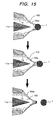
- the pigment aggregate 1 When the pigment aggregate 1 further grows and the electrostatic repulsion force F E exceeds the bonding force F esc , the pigment aggregate 1 escapes from the liquid ink surface 100a as illustrated in Fig. 15. Namely, when the radius of the pigment aggregate 1 grows more than the radius R esc ( hereinbelow called as escape radius R esc ) as represented by the mathematical formula (8), the pigment aggregate 1 flies out from the ink solvent 100.
- the escape radius R esc of the pigment aggregate 1 is in inverse proportional to ⁇ E, square root of the electric field E induced by the pulse voltage. For example, when substituting the following typical data for the parameters v, ⁇ , Q and ⁇ in the mathematical formula (8) and the resultant relationship between R esc and E is graphically illustrated in Fig. 16, the above inverse proportional relationship can be visually recognized.
- pigment aggregates 1 repeatedly fly out in a proper cycle of (c) ⁇ (f) from the top end of the discharge electrode 11a as illustrated in Fig. 18.
- the phenomenon as illustrated in Fig. 18 is caused in a lower portion of a cohesion region (220 in Fig. 24) which will be explained later.
- the aggregation force and the aggregation speed of the charged pigment particles 1a substantially increase, semispherical shaped or thick shell shaped pigment aggregates 190 tailing toward the discharge electrode 11a as illustrated in Fig. 20 begin to grow together with the spherical shaped pigment aggregates 1 as illustrated in Fig. 11.
- a minimum electric field (hereinbelow called as a second threshold electric field E'c) which causes to fly such semispherical shaped or thick shell shaped pigment aggregates 190 from the top end of the discharge electrode 11a can be derived according to the similar calculation sequence used for obtaining the first threshold value electric field Ec.
- a second threshold electric field E'c a minimum electric field which causes to fly such semispherical shaped or thick shell shaped pigment aggregates 190 from the top end of the discharge electrode 11a
- the second threshold value electric field E'c can be determined from the crossing point of two curves representing the derived two mathematical formulas as illustrated in Fig. 21. Further, the reason, why the two curves representing the radius R' con and the escape radius R' esc of the semispherical shaped pigment aggregate 190 is shifted toward upper right side with regard to the two curves (also illustrated in Fig. 17) representing the radius R con and the escape radius R esc of the spherical shaped pigment aggregate 1 as illustrated in Fig. 21, is that the volume of the semispherical shaped pigment aggregate 190 is only 1/2 of the volume of the spherical shaped pigment aggregate 1 having the same diameter as the semispherical shaped pigment aggregate 190.
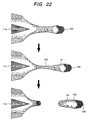
- the pigment aggregate 190 drags the ink solvent 100 at the back side thereof as illustrated in Fig. 22, therefore, the ink solvent 100 condensed near the liquid ink surface also flies while following in a string shape at the back side of the pigment aggregate 190. Further, the phenomenon as illustrated in Fig. 22 is induced in an upper portion in a cohesion and condensation coexistence region (221 in Fig. 24) which will also be explained later.
- the spherical shaped pigment aggregate 1 as shown in Fig. 11 hardly involves the ink solvent, because the back side thereof also a spherical shape and the above referred to tailing phenomenon never happens. Accordingly, if an electric field more than the second threshold value electric field E'c is applied at the top end of the discharge electrode 11a, a further larger pixel can be recorded on a recording medium. Further, since the ink solvent 100 likely deposits on the recording medium and because of its surface tension the pigments are prevented from being covered by dust, thereby, a further accurate recording can be performed.
- the reasons why the ink solvent 100 can fly continuously in this manner without being cut is that a pressure P due to the surface tension which acts to cut the ink solvent 100 is canceled out by the electrostatic repulsion force between the charged pigment particles 1a contained inside the ink solvent 100.
- Electric field regions which permit liquid ink drops to fly from the top end of the discharge electrode 11a are roughly classified into the following three regions as illustrated in Fig. 24.
- One is a cohesion region 220 from the first threshold value electric field Ec to the second threshold value electric field E'c, and in this region only the spherical shaped pigment aggregate 1 as illustrated in Fig. 11 flies out as the liquid ink drops. Further, although the ink discharge cycle is comparatively long, no extra charged pigment particles fly out from the top end of the discharge electrode 11a, therefore, fine pixels can be recorded on a recording medium, and thus such cohesion region 220 is suitable for a highly accurate recording.
- the remaining two belong to an electric field region more than the second threshold value electric field E'c.
- One of the two regions is the condensation region 222 in which only the semispherical shaped or the thick shell shaped pigment aggregates 190 as illustrated in Fig. 20 fly out, and the other region is the cohesion and condensation coexistence region 221 transiting from the cohesion region 220 to the condensation region 222.
- the ink solvent containing the charged pigment particles also fly together with the semispherical shaped or the thick shell shaped pigment aggregates 190 from the top end of the discharge electrode 11a, therefore, large pixels can be recorded with high speed in comparison with the operation in the cohesion region 220.
- Such condensation region 222 is suitable for a solid print recording.
- a line type recording head 11 made of a material having a low dielectric constant (such as acrylic resin and ceramics), an opposing electrode 10 made of a metal or a material having a high dielectric constant which is disposed so as to oppose to an ink discharge port of the recording head 10, an ink tank 12 in which ink prepared by dispersing charged pigment particles in a nonconductive ink medium, an ink circulating system for circulating the ink between the ink tank 12 and the recording head 11, a pulse voltage generating device 13 which applies a pulse voltage for pulling out ink drops for forming a unit pixel for image recording at respective discharge electrodes 11a, a driving circuit (not shown) which controls the pulse voltage generating device 13 in response to image data, a recording medium transferring mechanism (not shown) which causes to pass a recording medium A in a gap formed between the recording head 11 and the opposing electrode 10 and a controller (not shown) which controls the entire device.
- a line type recording head 11 made of a material having a low dielectric constant (such as
- the ink circulating system is constituted by two pipes 15a and 15b connecting between the recording head 11 and the ink tank 12 and two pumps 14a and 14b driven through control of the controller, and is divided into an ink feeding system for feeding ink to the recording head 11 and an ink collecting system for collecting ink from the recording head 11.
- the ink feeding system the ink is sucked up from the ink tank 12 by the pump 14a and is pressure-transferred via the pipe 15a to an ink feeding unit (20a in Figs. 2 and 3) in the recording head 11.
- the ink collecting system the ink is sucked from an ink collecting unit (20b in Figs. 2 and 3) in the recording head 11 by the pump 14b and is forcedly collected via the pipe 15b to the ink tank 12.
- the recording head 11 is provided with the ink feeding unit 20a in which the ink fed from the pipe 15a in the ink feeding system is spread into a line width, an ink flow passage 21 which guides the ink from the ink feeding unit 20a in a crest shape, the ink collecting unit 20b which connects the ink flow passage 21 with the pipe 15b in the ink collecting system, a slit shaped ink discharge port 22 which opens a top portion of the ink flow passage 21 toward the opposing electrode 11 with a proper width (of about 0.2mm), a plurality of discharge electrodes 11a arranged inside the ink discharge port 22 with a predetermined pitch (of about 0,2mm) and partition walls 23 made of a material having a low dielectric constant (for example, ceramics) which are respectively disposed both sides and upper side of the respective discharge electrodes 11a.
- the ink feeding unit 20a in which the ink fed from the pipe 15a in the ink feeding system is spread into a line width
- an ink flow passage 21 which guides the
- the respective discharge electrodes 11a are formed of a metal such as copper and nickel and on which surfaces a film of a material having a low dielectric constant and having a good wettability (for example, polyimide film) is formed which serves to prevent the pigment from sticking thereon. Further, the top ends of the respective discharge electrode 11a are shaped into a triangular pyramid and the respective triangular pyramids are projected from the ink discharge port 22 toward the opposing electrode 10 by a proper length (70 ⁇ m ⁇ 80 ⁇ m).
- the pulse voltage generating circuit 13 applies to the discharge electrodes 11a a high voltage signal formed by superposing a pulse top pulse Vp depending on the kind of the control signal on a bias voltage Vb, namely, a high voltage signal formed by superposing a pulse top pulse Vp which exceeds the minimum potential V'' for generating the electric field for the condensation region as illustrated in Fig.
- the pulse voltage generating circuit 13 is constituted by such as two pulse power sources which generate different potentials each other, a switching circuit which switches the two different potentials depending on the control signal from the driving circuit and a biasing power source which applies the biasing voltage Vb to the switching circuit, and when the first control signal is inputted from the driving circuit to the pulse voltage generating circuit 13, the switching circuit superposes the potential from the first pulse power source over the biasing voltage Vb during the existence of the input signal and outputs the same, and when the second control signal is inputted from the driving circuit to the pulse voltage generating circuit 13, the switching circuit superposes the potential from the second pulse power source over the biasing voltage Vd during the existence of the input signal and outputs the same.
- the controller drives the two pumps 14a and 14b in the ink circulating system.
- ink is pressure-transferred from the ink feeding unit 20a as well as the ink collecting unit 20b is placed in a negative pressure, and the ink flowing through the ink flow passage creeps up along the gaps defined by the respective partition walls 23 through capillary phenomenon to spread up to the top ends of the respective discharge electrodes 11a while wetting the same.
- a negative pressure is applied on the liquid ink surface near the top ends of the respective discharge electrodes 11a, and an ink meniscus is respectively formed at the top ends of the respective discharge electrodes 11a.
- the controller transfers the recording medium A in a predetermined direction through control of the recording medium transferring mechanism as well as applies either of the two kinds of high voltage signals to the respective discharge electrodes 11a through control of the driving circuit. Thereby, an image recording is performed either by the cohesion mode or by the condensation mode.
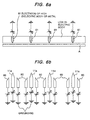
- auxiliary electrodes 60 at both sides of the discharge electrodes 11a as illustrated in Fig. 6(b) and a high or low potential which cancels out an electrical interaction between the adjacent respective discharge electrodes 11a is applied to the auxiliary electrodes 60, possible inconveniences can be avoided (for example, liquid ink drops fly out from the top ends of undesired discharge electrodes) which can be caused such as when high voltage signals are applied at the same time on mutually adjacent discharge electrodes 11a and when the pulse top potential is raised in order to increase the pixel density.
- These auxiliary electrodes 60 can be disposed as an intermediate layer while forming the partition walls 23 provided at both sides of the respective discharge electrodes 11a as laminates.
- the single piece of the opposing electrode 10 is simply grounded, however, as illustrated in Fig. 6(a) if the respective opposing electrodes 61 made of a metal or a material having a high dielectric constant are provided for every discharge electrode 11a and the potentials of the opposing electrode 61 and of the corresponding discharge electrode 11a are controlled in synchronism, the flying behavior of the liquid ink drops can be improved. Further, as illustrated in Fig. 7 if the pulse width of the pulse voltage to be added to the respective opposing electrodes 61 is determined while taking into account of the necessary time of the flying liquid ink drops to reach the recording medium, a possible scattering of the liquid ink drops is prevented.
- two kinds of pulses having mutually different pulse top potentials are superposed over the biasing voltage, however, if the pulse top potential is controlled further finely, a recording of further higher gradation can be realized. Still further, if a pulse width modulation is performed, a recording of still further higher gradation can, of course, be realized.
- the first threshold value electric field EC as has been referred to above is a minimum electric field necessary for growing the spherical shaped pigment aggregate 1 and the semispherical shaped pigment aggregate 190 up to the escape radius near the liquid ink surface, therefore, if such amount of electric field is simply applied to the top end of the discharge electrode 11a, it takes long time to grow the pigment aggregate 1 up to the escape radius as illustrated in Fig. 18, and the ink discharge cycle from the top end of the discharge electrodes 11a exceeds over 10 sec., thereby, a sufficient recording speed can not be obtained. In order to obtain a sufficient recording speed, it is necessary to increase the flying out frequency of the pigment aggregates 1 from the top end of the discharge electrode 11a as illustrated in Fig.
- the first threshold value electric field Ec is proportional to 3 ⁇ v, cubic root of surface tension v of the ink solvent, in other words, if the surface tension v of the ink solvent is suppressed, the first threshold value electric field Ec can be suppressed accordingly.
- a surface active agent which reduces the surface tension v of the ink solvent is added, the first threshold value electric field Ec is effectively suppressed.
- a surface tension of an organic solvent which is generally understood suitable for ink medium in view of its material property can be suppressed down to 13 ⁇ 14dyn/cm through addition of fluorine series surface active agents.
- the surface tension of water (accord to the present embodiment pure water so as to ensure non-conductivity thereof) is 72.5dyn/cm at 25°C of which use is desired in view of environment consideration, however, if a non-ion surface active agent is added thereto, the surface tension thereof is suppressed down to 20dyn/cm. Still further, the addition of a surface active agent is also useful for ensuring a proper viscosity of the ink.
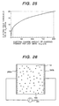
- the first threshold value electric field Ec is proportional to 3 ⁇ Q, cubic root of the electric charge amount Q of the charged pigment particles 1a per unit mass, in other words, if the electric charge amount Q of the charged pigment particles 1a per unit mass is suppressed, the first threshold value electric field Ec can be suppressed.
- the above referred to typical data for the parameters v, ⁇ and ⁇ in the mathematical formula (9) and a relationship between the obtained Q and Ec are graphically illustrated as in Fig. 25, the above fact can be visually recognized.
- a desirable first threshold value electric field Ec which unnecessitates the use of power semiconductor elements under the condition when the top end of the discharge electrode is shaped in an optimum shape (a triangular pyramid shape) is less than about 20MV/m, namely the electric charge amount Q of the charged pigment particles 1a in ink per unit mass is less than 200 ⁇ C/g. If the both values exceed the above limits, a potential of at least 6kV ⁇ 12kV has to apply to the discharge electrode 11a which necessities the use of power semiconductor elements.
- the electric charge amount Q of the charged pigment particles 1a in ink per unit mass less than about 200 ⁇ C/g.
- the electric charge amount of the charged pigment particles 1a per unit mass is oversuppressed, the following inconveniences are caused because of the excess reduction of the mutual electrostatic repulsion force between the charged pigment particles 1a: (1) the charged pigment particles 1a aggregate such as in the ink tank and the ink flow passages, and an ink having a predetermined density hardly circulates; (2) the ink clogs such as in the ink passage, and ink discharge stability reduces; (3) response speed of the charged pigment particles 1a reduces, and the recording speed reduces.
- the radius r of the charged pigment particles 1a in ink is reduced, the electric charge amount of the charged pigment particles 1a per unit mass reduces and the mutual electrostatic repulsion force of the charged pigment particles 1a also reduces, therefore, the above inconveniences (1), (2) and (3) can be caused like the above instance when the electric charge amount Q of the charged pigment particles 1a per unit mass is excessively reduced.
- the radius r of the charged pigment particles 1a reduces less than 0.1 ⁇ m, the above inconveniences is likely caused with a high possibility. Contrary, it the radius r of the charged pigment particles 1a becomes excessively large, the flow resistance effected by the ink solvent becomes large and the moving speed of the charged pigment particles 1a in the ink solvent reduces which reduces the recording speed.
- a proper radius r of the charged pigment particles 1a dispersed in the ink has to be determined in a range which prevents reduction in recording speed and avoids the occurrence of the above inconveniences (1), (2) and (3), namely in a range more than 0.1 ⁇ m and less than 5 ⁇ m.
- the above charged pigment particles 1a which contribute the formation of pixels to disperse one or two kinds of charged pigment particles in less than 50 vol% which prevent deposition and aggregation of the charged pigment particles 1a such as in the ink flow passages, for example, charged pigment particles having a larger electric charge amount than that of the charged pigment particles 1a or charged pigment particles having a larger particle diameter than that of the charged pigment particles 1a.
- the rate of such charged pigment particles in the ink is about 2 vol% ⁇ 10 vol%.
- the reason why the containing rate of such charged pigment particles in the ink is determined less than 10 vol% is that if the rate of the charged pigment particles in the ink exceeds the above value, the viscosity of the ink excessively increases and the response speed thereof delays.
- the reasons why the containing rate of such charged pigment particles in the ink is determined more than about 2 vol% is that if the rate of the charged pigment particles in the ink is selected more than about 2 vol%, a response frequency of about 1 ⁇ 10kHz can be realized as shown below.
- the containing rate of the charged pigment particles 1a in the ink is increased more than about 2 vol%, a plurality of vortexes are generated in the ink solvent 100 due to pigment density difference caused in the ink and the charged pigment particles 1a move rapidly along with the stream of these vortexes which permits to realize the response frequency of about 1 ⁇ 10kHz.
- the initial distribution of the charged pigment particles 1a in the ink solvent is uniform as illustrated in Fig.
- the ink used for the printer device according to the present embodiment it is preferable to prepare the ink used for the printer device according to the present embodiment to satisfy all of the above mentioned conditions, however, it will be acceptable if the same is prepared to satisfy at least one condition of the above.
- the top ends of the respective partition walls 23 are configurated in a sharp triangular shape as well as if the gap between the partition walls 23 disposed both sides of the discharge electrode 11a is gradually restricted toward the top end thereof, the liquid ink drops can be concentrated at the top end of the discharge electrodes 11a.
- a 20 channel recording head is obtained with the above discharge electrode structure.
- another 20 channel recording head is obtained with the partition walls 23 having a flat top end.
- the recording head is formed to have 100 ⁇ several thousands channels depending on the width of the recording medium.
- the width of the outlet slit formed by the partition walls 23 can be varied in a range of 5 ⁇ m ⁇ 30 ⁇ m and the entire width of the partition walls 23 can be varied in a range 30 ⁇ m ⁇ 100 ⁇ m.
- the top ends of the respective discharge electrodes 11a are a triangle shape and the top end angle thereof is about 60°. Further, the respective discharge electrodes 11a are thin films (film thickness of about 20 ⁇ m) made of such as Cu, Ag and Au, the partition walls 23 are polyimide and the base plate is a glass plate.
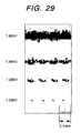
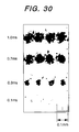
- Figs. 29 and 30 are enlarged view of black print dots printed by the printer device using the partition walls 23 having the triangle shaped top end portions.
- Fig. 29 is an enlarged view of print dots when the pulse width is fixed at 1,0msec.
- Fig. 30 is an enlarged view of print dots when the pulse voltage is fixed at 1.8kV, wherein the characteristics of the ink used and others are that the electric charge amount: 40 ⁇ C/g, the diameter of the pigment particle: 0.5 ⁇ m, solvent: isoper G, the biasing voltage: 1.0msec. and gap to the opposing electrode: 1.0mm.
- the print dot diameter can be varied either to large one or to small one. Further, a continuous solid print can be obtained.
- almost all of the print dots can be reduced to 3 ⁇ m ⁇ 5 ⁇ m, thereby, an extremely clear recording image can be obtained.
- the respective print dots are formed by an aggregation of fine particles less than 10 ⁇ m, thereby a further clear printing can be performed.
- a printer device can be realized which shows a high ink discharge stability and permits a highly accurate, fine and high gradation recording with a high speed.
Landscapes
- Particle Formation And Scattering Control In Inkjet Printers (AREA)
Applications Claiming Priority (2)
| Application Number | Priority Date | Filing Date | Title |
|---|---|---|---|
| JP30535098 | 1998-10-27 | ||
| JP10305350A JP2000127410A (ja) | 1998-10-27 | 1998-10-27 | プリンター装置 |
Publications (2)
| Publication Number | Publication Date |
|---|---|
| EP0997282A2 true EP0997282A2 (de) | 2000-05-03 |
| EP0997282A3 EP0997282A3 (de) | 2000-07-26 |
Family
ID=17944062
Family Applications (1)
| Application Number | Title | Priority Date | Filing Date |
|---|---|---|---|
| EP99120876A Withdrawn EP0997282A3 (de) | 1998-10-27 | 1999-10-27 | Druckvorrichtung |
Country Status (5)
| Country | Link |
|---|---|
| US (1) | US6328426B1 (de) |
| EP (1) | EP0997282A3 (de) |
| JP (1) | JP2000127410A (de) |
| KR (1) | KR20000029341A (de) |
| CA (1) | CA2287665A1 (de) |
Cited By (2)
| Publication number | Priority date | Publication date | Assignee | Title |
|---|---|---|---|---|
| WO2009147619A1 (en) * | 2008-06-02 | 2009-12-10 | University Of Cape Town | Inkjet printing of nanoparticulate functional inks |
| CN105291585A (zh) * | 2014-07-18 | 2016-02-03 | 深圳市比欧特光电有限公司 | 电子笔、打印设备和打印方法 |
Families Citing this family (16)
| Publication number | Priority date | Publication date | Assignee | Title |
|---|---|---|---|---|
| JP3975272B2 (ja) | 2002-02-21 | 2007-09-12 | 独立行政法人産業技術総合研究所 | 超微細流体ジェット装置 |
| TWI252053B (en) | 2002-09-24 | 2006-03-21 | Sharp Kk | Active matrix type organic EL display, and manufacturing method and device thereof, and liquid crystal array and manufacturing method thereof, and manufacturing method and device of color filter substrate, and color filter device |
| AU2003264539A1 (en) | 2002-09-24 | 2004-04-19 | Konica Minolta Holdings, Inc. | Electrostatic suction type fluid jettint device |
| WO2005014180A1 (ja) | 2003-08-08 | 2005-02-17 | Sharp Kabushiki Kaisha | 静電吸引型流体吐出方法及びその装置 |
| JP2005059215A (ja) | 2003-08-08 | 2005-03-10 | Sharp Corp | 静電吸引型流体吐出装置 |
| US7712874B2 (en) | 2003-08-08 | 2010-05-11 | Sharp Kabushiki Kaisha | Electrostatic suction type fluid discharge device, electrostatic suction type fluid discharge method, and plot pattern formation method using the same |
| JP4044012B2 (ja) | 2003-08-29 | 2008-02-06 | シャープ株式会社 | 静電吸引型流体吐出装置 |
| JP2005329558A (ja) * | 2004-05-18 | 2005-12-02 | Fuji Photo Film Co Ltd | インクジェット記録方法 |
| EP1961574B1 (de) * | 2005-12-09 | 2013-01-23 | Sharp Kabushiki Kaisha | Flüssigkeitstropfenausstosseinheit und flüssigkeitstropfenausstossvorrichtung |
| JP4895723B2 (ja) * | 2006-08-23 | 2012-03-14 | 富士フイルム株式会社 | 液体吐出装置および液体吐出面の清掃方法 |
| JP5002232B2 (ja) * | 2006-10-06 | 2012-08-15 | キヤノン株式会社 | インクジェット記録装置 |
| US7972105B2 (en) * | 2007-05-10 | 2011-07-05 | General Electric Company | Turbine anti-rotating stall schedule |
| US8373732B2 (en) * | 2007-08-22 | 2013-02-12 | Ricoh Company, Ltd. | Liquid droplet flight device and image forming apparatus with electrowetting drive electrode |
| CN103522761B (zh) * | 2013-10-15 | 2015-04-22 | 中国电子科技集团公司第四十八研究所 | 一种应用于超细栅太阳能电池的喷墨打印头 |
| CN105346250B (zh) * | 2015-12-03 | 2017-04-05 | 嘉兴学院 | 采用并联机构的电流体动力学纳米流体打印方法与装置 |
| CN107225857B (zh) * | 2016-03-25 | 2020-03-24 | 灿美工程股份有限公司 | 图形线形成装置及方法 |
Citations (3)
| Publication number | Priority date | Publication date | Assignee | Title |
|---|---|---|---|---|
| JPS564467A (en) | 1979-06-22 | 1981-01-17 | Nippon Telegr & Teleph Corp <Ntt> | Ink recording head |
| JPH0227445B2 (de) | 1979-07-04 | 1990-06-18 | Rieter Ag Maschf | |
| JPH08174815A (ja) | 1994-12-27 | 1996-07-09 | Nec Corp | インクジェットプリンタ |
Family Cites Families (5)
| Publication number | Priority date | Publication date | Assignee | Title |
|---|---|---|---|---|
| JPS5451837A (en) * | 1977-09-30 | 1979-04-24 | Ricoh Co Ltd | Ink jet head device |
| AU664404B2 (en) * | 1991-12-18 | 1995-11-16 | Tonejet Limited | Method and apparatus for the production of discrete agglomerations of particulate matter |
| JP3315268B2 (ja) * | 1994-09-22 | 2002-08-19 | 株式会社東芝 | 画像形成装置 |
| DE69609266T2 (de) | 1995-08-23 | 2000-11-30 | Nec Corp., Tokio/Tokyo | Tintenstrahldrucker zur Verwendung von Pigmentteilchen enthaltender Tinte |
| JP2859242B2 (ja) | 1997-04-04 | 1999-02-17 | 新潟日本電気株式会社 | 静電式インクジェット記録ヘッド |
-
1998
- 1998-10-27 JP JP10305350A patent/JP2000127410A/ja active Pending
-
1999
- 1999-10-27 US US09/427,627 patent/US6328426B1/en not_active Expired - Fee Related
- 1999-10-27 KR KR1019990046767A patent/KR20000029341A/ko not_active Ceased
- 1999-10-27 CA CA002287665A patent/CA2287665A1/en not_active Abandoned
- 1999-10-27 EP EP99120876A patent/EP0997282A3/de not_active Withdrawn
Patent Citations (3)
| Publication number | Priority date | Publication date | Assignee | Title |
|---|---|---|---|---|
| JPS564467A (en) | 1979-06-22 | 1981-01-17 | Nippon Telegr & Teleph Corp <Ntt> | Ink recording head |
| JPH0227445B2 (de) | 1979-07-04 | 1990-06-18 | Rieter Ag Maschf | |
| JPH08174815A (ja) | 1994-12-27 | 1996-07-09 | Nec Corp | インクジェットプリンタ |
Cited By (5)
| Publication number | Priority date | Publication date | Assignee | Title |
|---|---|---|---|---|
| WO2009147619A1 (en) * | 2008-06-02 | 2009-12-10 | University Of Cape Town | Inkjet printing of nanoparticulate functional inks |
| US8579415B2 (en) | 2008-06-02 | 2013-11-12 | Pst Sensors (Proprietary) Limited | Inkjet printing of nanoparticulate functional inks |
| RU2505416C2 (ru) * | 2008-06-02 | 2014-01-27 | Юниверсити Оф Кейптаун | Струйная печать функциональными чернилами с наночастицами |
| CN105291585A (zh) * | 2014-07-18 | 2016-02-03 | 深圳市比欧特光电有限公司 | 电子笔、打印设备和打印方法 |
| CN105291585B (zh) * | 2014-07-18 | 2017-07-25 | 深圳市比欧特光电有限公司 | 电子笔、印刷设备和印刷方法 |
Also Published As
| Publication number | Publication date |
|---|---|
| US6328426B1 (en) | 2001-12-11 |
| EP0997282A3 (de) | 2000-07-26 |
| KR20000029341A (ko) | 2000-05-25 |
| JP2000127410A (ja) | 2000-05-09 |
| CA2287665A1 (en) | 2000-04-27 |
Similar Documents
| Publication | Publication Date | Title |
|---|---|---|
| US6328426B1 (en) | Printer device | |
| JP3315268B2 (ja) | 画像形成装置 | |
| CN100532103C (zh) | 静电吸引式液体喷射头的制造方法,喷嘴板的制造方法,静电吸引式液体喷射装置 | |
| CA1082285A (en) | Method and apparatus for forming a liquid jet particularly suited for ink-jet printing | |
| CN1330429C (zh) | 超细流体喷射设备 | |
| US4314263A (en) | Fluid jet apparatus | |
| EP0245002A2 (de) | Tintenstrahldrucker | |
| JPS594310B2 (ja) | インクジェット記録装置 | |
| JP2013056545A (ja) | プリンティング装置 | |
| EP1016539A2 (de) | Verfahren und Gerät zur Bilderzeugung | |
| JP3071869B2 (ja) | 液体噴射記録装置及び記録方法 | |
| US6582054B2 (en) | Image forming apparatus | |
| JP4397642B2 (ja) | 静電吸引型流体吐出方法およびその装置 | |
| EP0778134B1 (de) | Tintenstrahlkopf für Tinte des Pigmenttypes mit Mittel zum Anlegen von verschiedenen Pulsen an den Elektroden | |
| TWI326637B (de) | ||
| JP2004136653A (ja) | 液体吐出装置 | |
| JPS63218363A (ja) | インクジエツト記録装置 | |
| JP2011092841A (ja) | ノズルクリーニング方法及び液滴製造方法 | |
| JP3969502B2 (ja) | 画像形成装置 | |
| JP3217837B2 (ja) | 液体噴射記録ヘッド | |
| EP3771565B1 (de) | Flüssigkeitsausstosskopf, flüssigkeitsausstossvorrichtung und flüssigkeitsausstossmodul | |
| US20080073026A1 (en) | Method of supplying liquid bonding material, method of manufacturing electronic circuit board, liquid bonding material supply apparatus and liquid bonding material | |
| EP0899105A2 (de) | Elektrostatischer Tintenstrahldruckkopf | |
| JPH0267140A (ja) | 液体噴射記録ヘッド | |
| JPH02178055A (ja) | インクジェットプリンタ |
Legal Events
| Date | Code | Title | Description |
|---|---|---|---|
| PUAI | Public reference made under article 153(3) epc to a published international application that has entered the european phase |
Free format text: ORIGINAL CODE: 0009012 |
|
| AK | Designated contracting states |
Kind code of ref document: A2 Designated state(s): DE FR GB IT NL |
|
| AX | Request for extension of the european patent |
Free format text: AL;LT;LV;MK;RO;SI |
|
| RIN1 | Information on inventor provided before grant (corrected) |
Inventor name: NAGAE, YOSHIHARU Inventor name: YONEKURA, SEIJI Inventor name: IMAZEKI, SHUJI Inventor name: FUJIWARA, SHIGETAKA Inventor name: SHINOHARA, HIDEKI Inventor name: CHAHN, LEE |
|
| PUAL | Search report despatched |
Free format text: ORIGINAL CODE: 0009013 |
|
| RIC1 | Information provided on ipc code assigned before grant |
Free format text: 7B 41J 2/095 A, 7B 41J 2/06 B |
|
| AK | Designated contracting states |
Kind code of ref document: A3 Designated state(s): AT BE CH CY DE DK ES FI FR GB GR IE IT LI LU MC NL PT SE |
|
| AX | Request for extension of the european patent |
Free format text: AL;LT;LV;MK;RO;SI |
|
| 17P | Request for examination filed |
Effective date: 20010116 |
|
| AKX | Designation fees paid |
Free format text: DE FR GB IT NL |
|
| STAA | Information on the status of an ep patent application or granted ep patent |
Free format text: STATUS: THE APPLICATION HAS BEEN WITHDRAWN |
|
| 18W | Application withdrawn |
Effective date: 20060131 |