EP0997312A1 - Schablonendruckmaschine - Google Patents
Schablonendruckmaschine Download PDFInfo
- Publication number
- EP0997312A1 EP0997312A1 EP99308477A EP99308477A EP0997312A1 EP 0997312 A1 EP0997312 A1 EP 0997312A1 EP 99308477 A EP99308477 A EP 99308477A EP 99308477 A EP99308477 A EP 99308477A EP 0997312 A1 EP0997312 A1 EP 0997312A1
- Authority
- EP
- European Patent Office
- Prior art keywords
- ink
- printing drum
- ink container
- printing
- lighting
- Prior art date
- Legal status (The legal status is an assumption and is not a legal conclusion. Google has not performed a legal analysis and makes no representation as to the accuracy of the status listed.)
- Withdrawn
Links
Images





Classifications
-
- B—PERFORMING OPERATIONS; TRANSPORTING
- B41—PRINTING; LINING MACHINES; TYPEWRITERS; STAMPS
- B41L—APPARATUS OR DEVICES FOR MANIFOLDING, DUPLICATING OR PRINTING FOR OFFICE OR OTHER COMMERCIAL PURPOSES; ADDRESSING MACHINES OR LIKE SERIES-PRINTING MACHINES
- B41L13/00—Stencilling apparatus for office or other commercial use
- B41L13/04—Stencilling apparatus for office or other commercial use with curved or rotary stencil carriers
- B41L13/06—Stencilling apparatus for office or other commercial use with curved or rotary stencil carriers with a single cylinder carrying the stencil
-
- B—PERFORMING OPERATIONS; TRANSPORTING
- B41—PRINTING; LINING MACHINES; TYPEWRITERS; STAMPS
- B41L—APPARATUS OR DEVICES FOR MANIFOLDING, DUPLICATING OR PRINTING FOR OFFICE OR OTHER COMMERCIAL PURPOSES; ADDRESSING MACHINES OR LIKE SERIES-PRINTING MACHINES
- B41L13/00—Stencilling apparatus for office or other commercial use
- B41L13/18—Inking units
Definitions
- the present invention relates to a stencil printing machine wherein printing is conducted by a printing drum having a stencil sheet wrapped thereon. More specifically, the stencil printing machine is such that an ink container detachably attached to the printing drum is lightened by lighting means to facilitate maintenance operation.
- FIG. 7 is a perspective view illustrating a printing drum detachably attached to a stencil printing machine.
- the printing drum 50 is mounted therein.
- An ink container 51 is detachably attached to an approximately center position inside the printing drum 50.
- the ink container 50 stores ink therein.
- FIG. 8 is a perspective view illustrating a constitution of ink supplying means 55 in the printing drum 50. This drawing is a view seen in a direction approximately opposite to that of FIG. 7, namely having a viewpoint in a rear side of the machine.
- An ink motor 56 sucks ink stored in the ink container 51 and supplies the ink onto a squeegee roller 58 through plural holes formed in a tube-like distributor 57.
- a doctor roller 59 is situated adjacent to the squeegee roller 58 at a small distance, i.e. a gap, away from the squeegee roller.
- the ink is accumulated to a predetermined quantity between the squeegee roller 58 and the doctor roller 59, thereby forming an ink swirl "A" with a uniform thickness while being rotated by a mixing shaft 60 situated therein.
- the ink supplying means 55 has an ink sensor 63 used for stabilizing ink supply from the ink container 51.
- the ink sensor 63 is attached to a board 65 situated above the ink swirl "A" inside the printing drum 50.
- the ink sensor 63 has two needle-shaped electrodes, a long one 63b and a short one 63a, each extending downwards from the board 65 for detecting quantity of the ink.
- suction by the ink motor 56 is controlled so that quantity of ink in the ink swirl "A" is kept constant while being detected by the electrode 63b or 63a between two end-points thereof.
- the ink supplying means 55 is situated inside the printing drum 50. Consequently, the ink container 51 must be detached from the printing drum when an operator is required to see a position of the ink swirl "A" in order to conduct a performance test of the ink supplying means 55 during assembling the machine and an in-serve maintenance operation. And, the operator is forced to see the position through a narrow access opening comparable to a diameter of the ink container 51.
- the operator manages to conduct the maintenance operation, lighting the position by a flashlight from outside the machine; however, lighting the position is difficult to conduct properly, and the operation itself is not easy since one hand of the operator is occupied by the flashlight.
- temperature inside the printing drum 50 is expected not to fluctuate as long as possible. Namely, fluctuation of the temperature inside the printing drum 50 changes viscosity of the ink, thereby finally affecting printing quality.
- the present invention is as claimed in the claims and which provides a stencil printing machine such that an operator can see the inside of the printing drum easily without affecting temperature thereof, and a lifetime of lighting means for lighting a position to be checked can be effectively used.
- a stencil printing machine as defined in a first aspect of the present invention comprises a printing drum rotationally driven around a central axis thereof and adapted to receive a perforated stencil sheet around an outer circumferential surface thereof; an ink container detachably attached to the printing drum, the ink container having ink therein; ink supplying means situated inside the printing drum to be seen through an opening formed in the printing drum when the ink container is detached from the printing drum; the ink supplying means supplying the ink to an inner circumferential surface of the printing drum; and lighting means for lightening the ink supplying means when the ink container is detached from the printing drum.
- the ink supplying means comprises a board and a temperature sensor situated on the board for detecting temperature of the ink, and the lighting means is attached to the board.
- a stencil printing machine as defined in a third aspect of the present invention in the stencil printing machine of the first aspect, further comprises an ink container detecting means for detecting whether the ink container is attached to the printing drum, and a controller for switching the lighting means upon detection of the ink container by the ink container detecting means.
- a stencil printing machine as defined in a fourth aspect of the present invention in the stencil printing machine of the third aspect, further comprises a front cover openably attached to the stencil printing machine for covering the printing drum, and cover detecting means for detecting opening and closing of the front cover, further the controller operates said lighting means to turn on when the cover detecting means detects opening of the front cover and the ink container detecting means detects detachment of the ink container from the printing drum, and the controller operates the lighting means not to turn on when the cover detecting means detects closing of the front cover or the ink container detecting means detects attachment of the ink container to the printing drum.
- the ink supplying means situated inside the printing drum can be seen by an operator if the ink container is detached from the printing drum. Since the lighting means is situated to the ink supplying means, maintenance and checking operation can be easily conducted.
- the lighting means is energized only when necessary, namely in a period when the front cover is opened and the ink container is detached. That improves a lifetime of the lighting means and prevents an inner temperature from rising.
- FIG. 1 is a front view illustrating the stencil printing machine.
- a stencil sheet perforated according to an image is wrapped around an outer circumferential surface of a printing drum 1.
- a printing sheet 2 supplied from a sheet supplying section 2 is conveyed between the printing drum 1 and a press roller 3 contacting thereto by rotation of the printing drum 1.
- the press roller 3 presses the printing sheet against the printing drum 1.
- Ink supplied from an inside of the printing drum passes through perforations of the stencil sheet, and then transfers onto the printing sheet, thereby forming an image thereon. After printed, the printing sheet is discharged to a sheet discharge section 4.
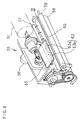
- FIG. 2 is a front view illustrating an inside of the printing drum.
- FIG. 3 is a block diagram showing an electrical constitution of the stencil printing machine.
- the ink supplying means 55 as explained above is situated inside the printing drum 1, the ink supplying means 55 as explained above is situated. Ink is dropped from the distributor 57, accumulating to a predetermined quantity between the squeegee roller 58 and the doctor roller 59, thereby forming an ink swirl "A" with a uniform thickness while being rotated by a not-shown mixing shaft situated therein.
- the ink sensor 63 is attached to a board 10 situated above the ink swirl "A" inside the printing drum 1.
- the board 10 is fixedly arranged at a required position.
- the ink sensor 63 as described before, a temperature sensor 15, and lightening means 18 are attached to the board 10.
- the board 10 is formed small to save space; therefore, the ink sensor 63, the temperature sensor 15, and the lighting means 18 are arranged thereon adjacent to each other.
- the ink sensor 63 has two needle-shaped electrodes, a long one and a short one, each extending downwards from the board 10 for detecting quantity of the ink in the ink swirl "A".
- the electrodes output a detecting signal into control means 30 disposed inside the machine but outside the printing drum 1.
- the control means 30 controls suction by the ink motor so that quantity of ink in the ink swirl "A" is kept constant while being detected by the electrodes between two end-points thereof.
- the temperature sensor 15 includes a thermistor, and detects temperature inside the printing drum 1 to output a temperature signal into the control means 30. Viscosity of ink changes according to temperature, and changes in viscosity of ink affects printing quality.
- atmospheric temperature inside the printing drum 1 is regarded as temperature of the ink, and outputted into the control means 30.
- the control means 30 controls pressing force of the press roller 3 according to temperature of the ink. In this way, uniform printed matter can be obtained in spite of fluctuation of temperature.
- the lighting means 18 includes an incandescent ramp, and emits white light towards the ink swirl "A". lighting by the lighting means 18 clearly show a state of the ink swirl "A", thereby facilitating maintenance operation of the machine. On-off operation of the lighting means 18 is controlled by the control means 30.
- the ink container 51 is inserted into the printing drum 1 from a front side of the machine and detachably attached thereto.
- the printing drum 1 has an ink container detecting device 20 therein.
- the ink container detecting device 20 outputs a signal indicating whether the container is attached to the drum, and the signal is received by the control means 30.
- the ink container detecting device 20 may be a micro-switch switching a contact thereof according to attachment and detachment of the ink container 51.
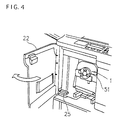
- FIG. 4 is a perspective view of the machine.
- a front cover 22 is provided to the front side of the machine adjacent to the printing drum 1. When the front cover 22 is opened, various maintenance operations such as checking the printing drum 1, attachment and detachment of the ink container 51, and checking the ink swirl "A" can be conducted.
- a cover detecting means 25 is provided to the machine for detecting opening and closing of the front cover 22.
- the cover detecting means 25 outputs a signal indicating a state of the front cover 22, and the signal is received by the control means 30.
- the cover detecting means 25 also may be a micro-switch.
- the control means 30 controls perforating and printing operation, and switching of the lighting means 18.
- the control of switching the lighting means 18 is conducted based on the signals inputted from the ink container detecting device 20 and the cover detecting means 25.
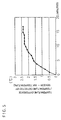
- FIG. 5 is a graph showing a relation between elapsed time after lighting means is energized and temperature difference between temperature detected by a temperature sensor and actual temperature of the ink.
- the lighting means 18 is an incandescent ramp, and it emits heat when energized.
- the heat emitted affects the temperature sensor 15 situated to the board 10 adjacent to the lighting means 18.
- the ink in the ink swirl "A" has a high specific heat capacity.
- the control means 30 controls pressing force of the pressing roller based on the detected temperature different from the actual temperature of the ink. That may deteriorates printing quality.
- the lighting means 18 is energized only when necessary.
- FIG. 6 is a flow chart showing on-off control of the lighting means 18.
- That control is conducted continuously and periodically at a predetermined interval as an interrupt control when a power supply of the stencil printing machine is switched on.
- the lighting means 18 is selectively turned on or turned off according to opening or closing state of the front cover 22 and attachment or detachment of the ink container 51. Opening or closing state of the front cover 22 is detected by the cover detecting means 25. Attachment or detachment of the ink container 51 is detected by the ink container detecting device 20.
- the lighting means 18 is lit only in the time when the front cover 22 is opened, the ink container 51 is detached, and then the ink swirl "A" can be seen.
- Heat emitted from the lighting means 18 in maintenance operation escapes through the access opening out of the drum. Therefore, temperature difference between temperature detected by the temperature sensor and actual temperature of the ink can be decreased.
- the stencil printing machine can not conduct printing. Meanwhile, the control means 30 does not receive a detection signal from the temperature sensor 15. Even in the case where ink temperature is detected improperly under influence of the lighting means 18, printing is not conducted and printed matter with poor printing quality is not produced.
- control means 30 operates the lighting means 18 to turn off in a most part of operating time of the machine such as perforating or printing time.
- the temperature sensor 15 Since the lighting means 18 is kept being turned off in such operating time of the machine, the temperature sensor 15 is not affected by heat of the lighting means 18. Accordingly, the temperature sensor 15 can properly detect temperature of the ink inside the printing drum 1, so that printing quality can be kept to a stable level without being deteriorated.
- the constitution as described above can cope with a rare case where the front cover 22 is closed when the ink container 51 is not attached.
- a simplified embodiment such that the lighting means 18 is operated only on the basis of attachment and detachment of the ink container 51 is also useful.
- the lighting means 18 is attached to a small space inside the printing drum 1, exchange of that conventionally requires time for disassembling the printing drum 1 and so on. But, according to the present invention, lifetime of the lighting means 18 can be effectively used since it is turned on only when necessary, so that frequency of the exchange decreases and time required for that can be shortened in total.
- the lighting means 18 is attached to the board 10, which the temperature sensor 15 is attached to.
- the lighting means 18 and the temperature sensor 15 may be attached to different boards. However, they are required to be arranged adjacent to each other in the small space to utilize it.
- the 1 lighting means can light a necessary portion inside the printing drum for facilitating maintenance operation since it is situated inside thereof.
- the lighting means is attached to the same board as the temperature sensor is attached to. Accordingly, the necessary portion inside the drum can be appropriately lightened by the lighting means when examining the ink swirl and so on without providing an additional board for attachment of the lighting means.
- the temperature sensor can properly detect temperature of the ink since it is not likely to be affected by the lighting means situated adjacent thereto. That prevents printing quality from deteriorating and improves lifetime of the lighting means.
- the lighting means is turned on only when opening of the front cover as well as detachment of the ink container is detected, the lighting means can function only in a necessary time for the maintenance operation. That improves effects described above.
Landscapes
- Inking, Control Or Cleaning Of Printing Machines (AREA)
Applications Claiming Priority (2)
| Application Number | Priority Date | Filing Date | Title |
|---|---|---|---|
| JP30417598 | 1998-10-26 | ||
| JP10304175A JP2000127600A (ja) | 1998-10-26 | 1998-10-26 | 孔版印刷装置 |
Publications (1)
| Publication Number | Publication Date |
|---|---|
| EP0997312A1 true EP0997312A1 (de) | 2000-05-03 |
Family
ID=17929951
Family Applications (1)
| Application Number | Title | Priority Date | Filing Date |
|---|---|---|---|
| EP99308477A Withdrawn EP0997312A1 (de) | 1998-10-26 | 1999-10-26 | Schablonendruckmaschine |
Country Status (3)
| Country | Link |
|---|---|
| US (1) | US6123022A (de) |
| EP (1) | EP0997312A1 (de) |
| JP (1) | JP2000127600A (de) |
Families Citing this family (8)
| Publication number | Priority date | Publication date | Assignee | Title |
|---|---|---|---|---|
| JP2000164480A (ja) * | 1998-11-24 | 2000-06-16 | Canon Inc | 半導体製造装置およびデバイス製造方法 |
| JP4672843B2 (ja) * | 2000-09-12 | 2011-04-20 | 東北リコー株式会社 | 孔版印刷装置 |
| CN1680114A (zh) * | 2004-04-06 | 2005-10-12 | 理想科学工业株式会社 | 模版印刷机 |
| GB0900431D0 (en) | 2009-01-12 | 2009-02-11 | Emerson & Renwick Ltd | Printing methods and related apparatus |
| RU2506165C2 (ru) * | 2008-08-22 | 2014-02-10 | Эмерсон Энд Ренвик Лтд | Устройство ротационной печати изображений на рулоне, система ротационной печати рисунка и способ печати изображений на рулоне (варианты) и рулон (варианты) |
| JP5683288B2 (ja) * | 2011-01-21 | 2015-03-11 | 株式会社ムサシ | 投票用紙交付装置 |
| JP6076646B2 (ja) * | 2011-08-17 | 2017-02-08 | 株式会社小森コーポレーション | 印刷機のインキ供給装置 |
| JP5987046B2 (ja) * | 2014-12-03 | 2016-09-06 | 株式会社ムサシ | 投票用紙交付装置 |
Citations (2)
| Publication number | Priority date | Publication date | Assignee | Title |
|---|---|---|---|---|
| US5443557A (en) * | 1993-05-25 | 1995-08-22 | Riso Kagaku Corporation | Printing drum assembly for a stencil printing device |
| EP0805048A1 (de) * | 1996-05-01 | 1997-11-05 | Riso Kagaku Corporation | Schablonendruckvorrichtung |
Family Cites Families (8)
| Publication number | Priority date | Publication date | Assignee | Title |
|---|---|---|---|---|
| US4030409A (en) * | 1973-01-26 | 1977-06-21 | Addressograph Multigraph Corporation | Printing apparatus controls |
| US4044671A (en) * | 1974-07-31 | 1977-08-30 | Addressograph-Multigraph Corporation | Duplicating apparatus employing modulator screen cylinder |
| US4088800A (en) * | 1976-01-12 | 1978-05-09 | Computer Ribbon Systems, Inc. | Method for cleaning and re-inking printer ribbons |
| FR2633062B1 (fr) * | 1988-06-21 | 1992-11-27 | Dubuit Mach | Procede pour le controle de qualite d'une impression, et machine d'impression mettant en oeuvre un tel procede |
| JP2691056B2 (ja) * | 1990-07-17 | 1997-12-17 | 三菱重工業株式会社 | 印刷機の版面上の水膜検出器 |
| JP3292535B2 (ja) * | 1993-03-01 | 2002-06-17 | 理想科学工業株式会社 | 孔版印刷装置および版胴 |
| JP3364865B2 (ja) * | 1993-11-12 | 2003-01-08 | 理想科学工業株式会社 | 印刷画像左右位置調節手段を備えた孔版印刷機 |
| JP3523941B2 (ja) * | 1995-07-28 | 2004-04-26 | 理想科学工業株式会社 | 孔版印刷装置 |
-
1998
- 1998-10-26 JP JP10304175A patent/JP2000127600A/ja active Pending
-
1999
- 1999-10-22 US US09/425,219 patent/US6123022A/en not_active Expired - Fee Related
- 1999-10-26 EP EP99308477A patent/EP0997312A1/de not_active Withdrawn
Patent Citations (2)
| Publication number | Priority date | Publication date | Assignee | Title |
|---|---|---|---|---|
| US5443557A (en) * | 1993-05-25 | 1995-08-22 | Riso Kagaku Corporation | Printing drum assembly for a stencil printing device |
| EP0805048A1 (de) * | 1996-05-01 | 1997-11-05 | Riso Kagaku Corporation | Schablonendruckvorrichtung |
Also Published As
| Publication number | Publication date |
|---|---|
| US6123022A (en) | 2000-09-26 |
| JP2000127600A (ja) | 2000-05-09 |
Similar Documents
| Publication | Publication Date | Title |
|---|---|---|
| US6123022A (en) | Stencil printing machine | |
| US5699731A (en) | Ink-supply control device and stencil printing machine having the same | |
| EP2177359A1 (de) | Flüssigtranskriptionsvorrichtung | |
| EP1000766A1 (de) | Schablonendruckvorrichtung | |
| JP2000094732A (ja) | ポータブルプリンタ | |
| JP2004255585A (ja) | 画像形成装置 | |
| US6206591B1 (en) | Sheet carrying device | |
| EP1600302A1 (de) | Verfahren und vorrichtung für schablonendruck sowie tintenbehälter | |
| JP2001341290A (ja) | マスタ収納物及びインキ収納容器の識別方法並びに印刷装置 | |
| EP4166334A1 (de) | Drucksystem einer offsetrotationsdruckmaschine und offsetrotationsdruckmaschine | |
| JP3566367B2 (ja) | 孔版印刷装置 | |
| JP4532707B2 (ja) | 印刷ドラム用ケースユニット | |
| JP2007175965A (ja) | 印刷機 | |
| JP3494589B2 (ja) | 孔版印刷装置 | |
| JP3731018B2 (ja) | 孔版印刷装置 | |
| JP4921030B2 (ja) | 孔版印刷装置 | |
| JP3949705B2 (ja) | 印刷機におけるインキと湿し水の供給方法 | |
| JP3879915B2 (ja) | 印刷機におけるインキつぼ内のインキ不足検出方法 | |
| JP3645111B2 (ja) | 孔版印刷方法及び装置 | |
| JP4219437B2 (ja) | 印刷装置 | |
| JP2000280452A (ja) | 画像形成装置の異物除去装置 | |
| JPH09300806A (ja) | 薄肉版胴型輪転孔版印刷機ならびに該印刷機のインク馴染み運転方法および印刷運転方法 | |
| JP2902295B2 (ja) | 製版印刷装置 | |
| JP2003312094A (ja) | プリンタ装置 | |
| JPH1016372A (ja) | 印刷装置 |
Legal Events
| Date | Code | Title | Description |
|---|---|---|---|
| PUAI | Public reference made under article 153(3) epc to a published international application that has entered the european phase |
Free format text: ORIGINAL CODE: 0009012 |
|
| 17P | Request for examination filed |
Effective date: 19991106 |
|
| AK | Designated contracting states |
Kind code of ref document: A1 Designated state(s): DE FR GB |
|
| AX | Request for extension of the european patent |
Free format text: AL;LT;LV;MK;RO;SI |
|
| AKX | Designation fees paid |
Free format text: DE FR GB |
|
| GRAH | Despatch of communication of intention to grant a patent |
Free format text: ORIGINAL CODE: EPIDOS IGRA |
|
| STAA | Information on the status of an ep patent application or granted ep patent |
Free format text: STATUS: THE APPLICATION IS DEEMED TO BE WITHDRAWN |
|
| 18D | Application deemed to be withdrawn |
Effective date: 20030205 |