EP0997367A2 - Chassis de poussette pour enfants ou poupées - Google Patents
Chassis de poussette pour enfants ou poupées Download PDFInfo
- Publication number
- EP0997367A2 EP0997367A2 EP99115372A EP99115372A EP0997367A2 EP 0997367 A2 EP0997367 A2 EP 0997367A2 EP 99115372 A EP99115372 A EP 99115372A EP 99115372 A EP99115372 A EP 99115372A EP 0997367 A2 EP0997367 A2 EP 0997367A2
- Authority
- EP
- European Patent Office
- Prior art keywords
- locking
- chassis according
- longitudinal
- sliding
- spar
- Prior art date
- Legal status (The legal status is an assumption and is not a legal conclusion. Google has not performed a legal analysis and makes no representation as to the accuracy of the status listed.)
- Granted
Links
- 210000000078 claw Anatomy 0.000 claims description 6
- 239000002904 solvent Substances 0.000 claims description 2
- 230000001360 synchronised effect Effects 0.000 claims description 2
- 230000008878 coupling Effects 0.000 description 9
- 238000010168 coupling process Methods 0.000 description 9
- 238000005859 coupling reaction Methods 0.000 description 9
- 230000007246 mechanism Effects 0.000 description 4
- 230000008901 benefit Effects 0.000 description 2
- 230000008859 change Effects 0.000 description 2
- 230000000630 rising effect Effects 0.000 description 2
- 230000009471 action Effects 0.000 description 1
- 210000001520 comb Anatomy 0.000 description 1
- 230000006378 damage Effects 0.000 description 1
Images


Classifications
-
- B—PERFORMING OPERATIONS; TRANSPORTING
- B62—LAND VEHICLES FOR TRAVELLING OTHERWISE THAN ON RAILS
- B62B—HAND-PROPELLED VEHICLES, e.g. HAND CARTS OR PERAMBULATORS; SLEDGES
- B62B7/00—Carriages for children; Perambulators, e.g. dolls' perambulators
- B62B7/04—Carriages for children; Perambulators, e.g. dolls' perambulators having more than one wheel axis; Steering devices therefor
- B62B7/06—Carriages for children; Perambulators, e.g. dolls' perambulators having more than one wheel axis; Steering devices therefor collapsible or foldable
- B62B7/08—Carriages for children; Perambulators, e.g. dolls' perambulators having more than one wheel axis; Steering devices therefor collapsible or foldable in the direction of, or at right angles to, the wheel axis
- B62B7/083—Carriages for children; Perambulators, e.g. dolls' perambulators having more than one wheel axis; Steering devices therefor collapsible or foldable in the direction of, or at right angles to, the wheel axis the wheel axes being moved from each other during folding
-
- B—PERFORMING OPERATIONS; TRANSPORTING
- B62—LAND VEHICLES FOR TRAVELLING OTHERWISE THAN ON RAILS
- B62B—HAND-PROPELLED VEHICLES, e.g. HAND CARTS OR PERAMBULATORS; SLEDGES
- B62B2205/00—Hand-propelled vehicles or sledges being foldable or dismountable when not in use
- B62B2205/20—Catches; Locking or releasing an articulation
-
- B—PERFORMING OPERATIONS; TRANSPORTING
- B62—LAND VEHICLES FOR TRAVELLING OTHERWISE THAN ON RAILS
- B62B—HAND-PROPELLED VEHICLES, e.g. HAND CARTS OR PERAMBULATORS; SLEDGES
- B62B9/00—Accessories or details specially adapted for children's carriages or perambulators
- B62B9/20—Handle bars; Handles
- B62B9/203—Handle bars; Handles movable from front end to rear end position
Definitions
- the invention relates to a chassis for a pram or doll's pram a chassis in conjunction with two collapsible scissors, whereby at one end of one of the synchronized legs of the scissors a slide is assigned a locking element, which in the sliding position in a Snap-in receptacle lockable and detachable for folding the chassis is.
- Such chassis are known and mostly enjoy as a stroller in Form of a sports car of great popularity.
- the collapsibility of the chassis makes it possible to easily carry the stroller even when space is limited to be able to transport.
- To fold are usually to the two longitudinal spars of the essential U-shaped slide two handle-like Sliding pieces provided with a locking pin that is attached to a corresponding Locking in the area of the scissors is engaged when the slide is in a sliding position, are motion-coupled, so that this Locking pin is loosened when tightening the sliding pieces and the slide and the scissors can practically collapse.
- a disadvantage of this type of Execution of the sliding pieces is that, for example, when the Strollers with a child sitting in them are lifted on a bus or the like Sliding pieces can be operated unintentionally when lifting, which in addition leads that the locking pin is released and the chassis quasi down can fold down.
- a trap is usually provided, which is the folding movement limited, there is a remarkably high uncertainty factor here, caused by the possibility that accidental actuation of this known sliding pieces is easily possible.
- the invention is therefore based on the problem of specifying a chassis largely unintentional actuation of the folding mechanism is excluded with the same simple handling at the same time.
- a rotating element rotatable about the longitudinal axis of the bar is provided, which is connected to a tension element coupled to the locking element, which when turning the rotating element along the longitudinal spar with entrainment the locking element is movable.
- the folding device according to the invention is particularly advantageous in Contrary to the prior art, a rotating element which is about the Longitudinal axis of the bar is to be rotated to release the respective locking element.
- the invention So it goes from the previously known sliding design, which is the beginning problems mentioned. Rotating the rotating element around the Longitudinal axis is inadvertently not possible, even if for example, to lift the stroller directly on the rotating element is attacked, this is at most claimed to train. Since two more Corresponding rotating elements are provided, which preferably in opposite directions unintentional loosening is excluded with particular advantage, however, the handling remains with regard to the simplicity of the to be carried out Movement still without problems.
- the rotary movement of the Rotating element can be converted into a longitudinal movement of the tension element.
- the rotary element can comprise a helix on which when rotating one, preferably two rollers connected to the pulling element run, for this purpose at the end of the inside of the longitudinal spar extending traction element a cross pin is provided, which has an elongated opening of the longitudinal spar and at its ends, i.e. outside the Holmes lying, the rollers are provided.
- the helix is fixed in position moved, the rollers run on the rising guide surface of the spiral, what leads to the fact that the tension element is tightened and the locking element accordingly is solved.
- the locking elements and / or the rotating element can be moved.
- the rotating element can be handled as a surrounding bar Be formed twist grip, or a twist grip-like part that interacts with the helix, include.
- the rotary handle-like Part of the rotating element can be in the longitudinal direction of the bar running external toothing and the handle part like a corresponding Have internal teeth, so that the actuation of the rotary handle-like part Helix can be taken over the meshing engagement.
- the angle of rotation should be be around 90 ° to ensure easy handling. Is next to it it is also conceivable, instead of a multi-part design of the rotary element to form the corresponding helix directly on the rotary handle.
- the slider can be folded according to the invention and can be locked in the respective end positions, with the slide Solvents are provided for releasing the latching, comprising two to the Sliding elements provided in the longitudinal direction, which can be pushed in the longitudinal direction of the spar, which are each connected to a further tension element, which with each another locking element is connected.
- a locking device can be assigned to each sliding element be, which locks the sliding element and to move it is pressed. An actuation of the sliding elements is therefore only possible if the respective locking device is released beforehand or simultaneously.
- the locking device can comprise a release button by means of which one in the interior of the longitudinal spar against one preferably generated by a leaf spring Restoring force of the stored locking pin, which is used to lock the respective Sliding device attacks, can be pressed in, so that it is then moved accordingly can be. So two steps are required here, firstly engaging the release button, on the other hand moving the sliding elements, so that an unintentional loosening is also excluded and a sudden folding of the car including the child e.g. while the Stroller, which can lead to serious injuries, is avoided.
- the inventive concept can be a sliding element with a rotating element in a common part be combined so that the part as a rotating or sliding element as required can be actuated.
- the combined part can, according to the invention, be a longitudinal spar surrounding rotary push handle be formed.
- the release button is in this case arranged on the common part. This then forms a complete one Actuating unit by means of which all change movements of the Chassis can be initiated.
- the helix can have one or two wall recesses Have receptacle of the rollers which are stationary when the sliding element is actuated, because the helix, which is part of the rotating element, when moving the Sliding element is taken, but the rollers remain in position.
- the Slider itself can be arranged on the scissor legs using fastening struts be, at the lower ends of the longitudinal spars pivotally mounted are, the slider for pivoting from one side to the other is pivoted about this pivot bearing, and being on the fastening struts the locking elements are provided for locking the slide must be engaged when setting up the chassis.
- These locking elements are with the pulling elements provided on the longitudinal spars can be detachably coupled, the means, the movement coupling is when the slide for pushing the other side is swung around, loosened, is to fold Then slide the slider back to the first side, then the locking elements be coupled again with the pulling elements so that they can be connected by means of the Rotating element can be actuated again. Merging is only one of them Side possible.
- the respective Sliding positions can be on each longitudinal spar, one sliding part with two on opposite Pages trained locking claws are provided, which with the sliding element via the tension element running outside the longitudinal spar is movable along the spar, furthermore in the region of the leg ends the scissors or the fastening struts provided corresponding locking receptacles are.
- the further locking elements themselves can be against one of a spring element generated restoring force can be moved from the locked position, what about this leads that these automatically lock when swiveling, since the spring element always pushes the locking elements into the locking position.
- Fig. 1 shows a stroller 1 according to the invention, consisting of a Chassis 2, which is not important in this case, which is why this is not described in more detail.
- Two are connected to the chassis Scissors 3, 4, which carry an insert 5 on which the child sits.
- a slide 6 For pushing a slide 6 is provided which has a substantially U-shape.
- the chassis can be folded up as shown in Fig. 9 next to it the slide 6 can also be pivoted to the other side.
- the slider 6 itself has two longitudinal spars 7, 8, which by means of two fastening struts 9, 10 are articulated at the end of a leg 11, 12 of the respective scissors 3, 4.
- Each longitudinal spar 7, 8 is connected to the respective fastening strut via an articulated connection 13 (see Fig. 7) connected.
- a locking element 14 is arranged in the form of a locking pin, which on a corresponding snap-in receptacle 15, 16 on another Legs 17, 18 of the scissors 3, 4 is added. This will the chassis locked and held in the set up shape.
- the locking element 14 is arranged on the longitudinal spar 7 sleeve-like coupling part 19 releasably by means of a coupling part 19 engaging Coupling pin 20, which is connected to the locking pin 14 and protrudes from the fastening strut, connected.
- the coupling part 19 in turn is with a tension element 21 running in the interior of the longitudinal spar 7 Form a tie rod connected via a corresponding bolt connection 22.
- Movement mechanism can be moved inside the longitudinal spar 7, so that the coupling part 19 is movable along the spar 7 (the bolt 22 moves then in the longitudinal opening 23), which then when driving the pin 20 retracted the respective locking element and released from the locking receptacle 15 8, as shown in Fig. 8, so that the locking is released and, as shown by arrow A in Fig. 8, the slider can fall down, the movement being carried out by a trap 24 which is separated, for example, by the foot must be solved to completely fold the frame, is braked.
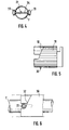
- FIGS. 2 to 6 The mechanism for releasing the latching element is shown in detail in FIGS. 2 to 6 described.
- Fig. 2 shows a common part 25, which on the respective longitudinal spar is arranged.
- a fastening section 26 is formed on part 25, which is attached to the spar by means of a bolt connection.
- a rotary element 27 which is used to move the Serves locking elements, and a sliding element 28, which for moving other Locking elements must be actuated to move the slide 6 from one to the other Page, which is described below.
- the part 25, which, see FIG. 3, surrounds handle 7 in a handle-like manner, has a handle-like part 29, which serves to move a coil 30 arranged inside.
- This Helix 30, which is provided with an external toothing 31, with a corresponding Internal toothing of the handle-like part 29 combs, is about the longitudinal axis of the bar rotatable and has two helically rising guide surfaces 32. On these guide surfaces run two rollers 33 (see Fig. 4) which are rotatable on one Cross pin 34 are arranged, which is connected to the pull rod 21, and which, see FIG. 7, penetrates a corresponding longitudinal opening 35 on the spar 7. Now, starting from the starting position shown in Fig.
- FIGS. 11 to 13 it is also possible to slide 6 as well to flip to the other side, what by swinging around the hinge connection 13 takes place.
- a further locking element 36 also applies to the longitudinal spar 8
- the one locking claw 38 is in engagement with a locking receptacle 39 which in Area of the upper end of the fastening strut 9 is formed.
- This sliding element is also common Part 25 formed, that is, this is both the rotating element as well as the sliding element.
- the sliding element 28 comprises, see 2 and 3, a sliding piece 41, which the spar 7 also sleeve-like surrounds.
- a push button 42 is provided on this sliding piece 41 by means of which one stored inside the spar against the action of a leaf spring 43 Locking pin 44 can be pressed inwards.
- This locking pin 44 is part of a locking device, which serves to lock the sliding element 48 in this way to avoid unintentional actuation.
- the actuation of the sliding element is based on that shown in FIG. 3 Position explained in connection with Fig. 10.
- the push button 42 To the sliding element at all to be able to operate, the push button 42 must first be pressed, which leads to that the adjacent locking pin 44 is pressed into the spar interior, see Arrow C in Fig. 11. This releases the locking of the sliding element 28, so that this, see arrow D in Fig. 11 and in Fig. 10 along the spar 7 moved can be.
- the sliding piece 41 is over the locking pin 44th pushed away. This will keep it down.
- too the rotary element 27, ie the handle-like part 29 and the helix 30, are also displaced. Only the fastening piece 26 remains unmoved. While moving engages around the recess 45 of the coil 30, the rollers 33, which also remain stationary when the sliding element is actuated.
Landscapes
- Engineering & Computer Science (AREA)
- Chemical & Material Sciences (AREA)
- Combustion & Propulsion (AREA)
- Transportation (AREA)
- Mechanical Engineering (AREA)
- Toys (AREA)
- Carriages For Children, Sleds, And Other Hand-Operated Vehicles (AREA)
- Adornments (AREA)
- Table Devices Or Equipment (AREA)
Priority Applications (1)
| Application Number | Priority Date | Filing Date | Title |
|---|---|---|---|
| DK99115372T DK0997367T3 (da) | 1998-10-28 | 1999-08-04 | Stel til en barne- eller dukkevogn |
Applications Claiming Priority (2)
| Application Number | Priority Date | Filing Date | Title |
|---|---|---|---|
| DE29819218U | 1998-10-28 | ||
| DE29819218U DE29819218U1 (de) | 1998-10-28 | 1998-10-28 | Fahrgestell für einen Kinder- oder Puppenwagen |
Publications (3)
| Publication Number | Publication Date |
|---|---|
| EP0997367A2 true EP0997367A2 (fr) | 2000-05-03 |
| EP0997367A3 EP0997367A3 (fr) | 2003-09-10 |
| EP0997367B1 EP0997367B1 (fr) | 2004-10-06 |
Family
ID=8064508
Family Applications (1)
| Application Number | Title | Priority Date | Filing Date |
|---|---|---|---|
| EP99115372A Expired - Lifetime EP0997367B1 (fr) | 1998-10-28 | 1999-08-04 | Chassis de poussette pour enfants ou poupées |
Country Status (4)
| Country | Link |
|---|---|
| EP (1) | EP0997367B1 (fr) |
| AT (1) | ATE278593T1 (fr) |
| DE (2) | DE29819218U1 (fr) |
| DK (1) | DK0997367T3 (fr) |
Cited By (5)
| Publication number | Priority date | Publication date | Assignee | Title |
|---|---|---|---|---|
| EP1238887A3 (fr) * | 2001-03-05 | 2003-12-17 | Combi Corporation | Voiture d'enfant pliable |
| US7686322B2 (en) | 2004-04-30 | 2010-03-30 | Chicco Usa, Inc. | Foldable stroller with memory recline |
| USD636300S1 (en) | 2009-08-14 | 2011-04-19 | Artsana Usa, Inc. | Stroller |
| US8262124B2 (en) | 2007-11-01 | 2012-09-11 | Artsana Usa, Inc. | Folding stroller actuating system |
| CN103502080A (zh) * | 2011-04-07 | 2014-01-08 | 丰泰斯蒂克有限公司 | 手指保护装置 |
Families Citing this family (6)
| Publication number | Priority date | Publication date | Assignee | Title |
|---|---|---|---|---|
| DE10330207B4 (de) * | 2003-07-03 | 2007-09-27 | Joh. Georg Hartan | Kinder- oder Puppenwagen |
| US8100429B2 (en) | 2008-03-31 | 2012-01-24 | Artsana Usa, Inc. | Three dimensional folding stroller with infant carrier attachment and one hand actuated seat recline |
| US8240700B2 (en) | 2008-08-15 | 2012-08-14 | Artsana Usa, Inc. | Stroller with travel seat attachment |
| EP2323888B1 (fr) | 2008-08-15 | 2015-01-21 | Artsana Usa Inc. | Poussette |
| USD651140S1 (en) | 2010-12-20 | 2011-12-27 | Artsana Usa, Inc. | Stroller frame tubing |
| US9855964B2 (en) * | 2016-02-29 | 2018-01-02 | Wonderland Switzerland Ag | Stroller frame |
Family Cites Families (6)
| Publication number | Priority date | Publication date | Assignee | Title |
|---|---|---|---|---|
| US3653681A (en) * | 1970-05-19 | 1972-04-04 | Julian A Virtue | Baby stroller |
| CA1316952C (fr) * | 1986-08-22 | 1993-04-27 | Shinroku Nakao | Voiture d'enfant pliable |
| JP2583063B2 (ja) * | 1987-06-26 | 1997-02-19 | アップリカ葛西株式会社 | 乳母車 |
| DE3884094T2 (de) * | 1987-07-28 | 1994-01-13 | Aprica Kassai Kk | Kinderwagen. |
| US5205579A (en) * | 1990-10-08 | 1993-04-27 | Combi Corporation | Handle bar for baby carriage |
| GB2319227B (en) * | 1996-11-11 | 2000-09-27 | Huang Li Chu Chen | Foldable mechanisim for a stroller |
-
1998
- 1998-10-28 DE DE29819218U patent/DE29819218U1/de not_active Expired - Lifetime
-
1999
- 1999-08-04 DK DK99115372T patent/DK0997367T3/da active
- 1999-08-04 DE DE59910728T patent/DE59910728D1/de not_active Expired - Lifetime
- 1999-08-04 EP EP99115372A patent/EP0997367B1/fr not_active Expired - Lifetime
- 1999-08-04 AT AT99115372T patent/ATE278593T1/de not_active IP Right Cessation
Non-Patent Citations (1)
| Title |
|---|
| None |
Cited By (8)
| Publication number | Priority date | Publication date | Assignee | Title |
|---|---|---|---|---|
| EP1238887A3 (fr) * | 2001-03-05 | 2003-12-17 | Combi Corporation | Voiture d'enfant pliable |
| US6893031B2 (en) | 2001-03-05 | 2005-05-17 | Combi Corporation | Folding stroller |
| CN1319796C (zh) * | 2001-03-05 | 2007-06-06 | 宫比株式会社 | 折叠式婴儿四轮车 |
| KR100852410B1 (ko) * | 2001-03-05 | 2008-08-14 | 콤비 가부시키가이샤 | 절첩식 유모차 |
| US7686322B2 (en) | 2004-04-30 | 2010-03-30 | Chicco Usa, Inc. | Foldable stroller with memory recline |
| US8262124B2 (en) | 2007-11-01 | 2012-09-11 | Artsana Usa, Inc. | Folding stroller actuating system |
| USD636300S1 (en) | 2009-08-14 | 2011-04-19 | Artsana Usa, Inc. | Stroller |
| CN103502080A (zh) * | 2011-04-07 | 2014-01-08 | 丰泰斯蒂克有限公司 | 手指保护装置 |
Also Published As
| Publication number | Publication date |
|---|---|
| DE29819218U1 (de) | 1999-03-25 |
| DK0997367T3 (da) | 2005-01-03 |
| EP0997367B1 (fr) | 2004-10-06 |
| ATE278593T1 (de) | 2004-10-15 |
| EP0997367A3 (fr) | 2003-09-10 |
| DE59910728D1 (de) | 2004-11-11 |
Similar Documents
| Publication | Publication Date | Title |
|---|---|---|
| EP2957479B1 (fr) | Structure de poussette et poussette | |
| DE60200063T2 (de) | Klappbarer Kinderwagen | |
| DE2823086C2 (de) | Kinderwagen mit einer für beide Fahrtrichtungen umstellbaren Schiebevorrichtung | |
| DE20011187U1 (de) | Zusammenklappbares Fahrgestell | |
| DE60200441T2 (de) | Dreifach faltbarer Kinderwagen | |
| EP0997367B1 (fr) | Chassis de poussette pour enfants ou poupées | |
| EP3512752B1 (fr) | Cadre de poussette et poussette | |
| DE3237214C2 (de) | Für beide Fahrtrichtungen umstellbare Schiebevorrichtung für Kinderwagen | |
| DE102012102531B4 (de) | Kinderwagen, seine rahmenbetätigungsanordnung und verfahren zum bedienen derselben | |
| DE1457245C3 (de) | Handgepäckstück großen Rauminhaltes mit Rädern | |
| EP1762459B1 (fr) | Châssis pour une poussette ou une voiture de poupée ainsi qu'une poussette ou une voiture de poupée | |
| DE4229857C2 (de) | Zusammenlegbares Fahrgestell für einen Kinderwagen | |
| EP1493646B1 (fr) | Voiture d'enfant ou de poupée | |
| WO2020057991A1 (fr) | Poussette | |
| DE69834530T2 (de) | Kinderwagen | |
| DE19538080A1 (de) | Transportvorrichtung für leichte Boote, Surfboards und dgl. | |
| DE202015001097U1 (de) | Kinderwagen | |
| DE102005029111B4 (de) | Dachreling für Fahrzeuge | |
| EP4088985B1 (fr) | Voiture d'enfant ou de poupée | |
| DE3007888C2 (fr) | ||
| WO2002034614A1 (fr) | Vehicule a planchette pose-pied et tige de blocage rabattable | |
| EP1491422B1 (fr) | Poussette ayant un mécanisme de pliage | |
| DE3050689C2 (de) | Verriegelungsvorrichtung für einen Klappkinderwagen | |
| DE102017122514B4 (de) | Schließmechanismus zum Verriegeln von zwei sich über Eck treffenden, relativ zueinander verschwenkbaren Bordwänden eines Kraftfahrzeugs oder eines Kraftfahrzeuganhängers | |
| EP4088988A1 (fr) | Liaison transversale pour une voiture d'enfant ou de poupée |
Legal Events
| Date | Code | Title | Description |
|---|---|---|---|
| PUAI | Public reference made under article 153(3) epc to a published international application that has entered the european phase |
Free format text: ORIGINAL CODE: 0009012 |
|
| AK | Designated contracting states |
Kind code of ref document: A2 Designated state(s): AT BE CH CY DE DK ES FI FR GB GR IE IT LI LU MC NL PT SE |
|
| AX | Request for extension of the european patent |
Free format text: AL;LT;LV;MK;RO;SI |
|
| PUAL | Search report despatched |
Free format text: ORIGINAL CODE: 0009013 |
|
| AK | Designated contracting states |
Kind code of ref document: A3 Designated state(s): AT BE CH CY DE DK ES FI FR GB GR IE IT LI LU MC NL PT SE |
|
| AX | Request for extension of the european patent |
Extension state: AL LT LV MK RO SI |
|
| 17P | Request for examination filed |
Effective date: 20031108 |
|
| GRAP | Despatch of communication of intention to grant a patent |
Free format text: ORIGINAL CODE: EPIDOSNIGR1 |
|
| 17Q | First examination report despatched |
Effective date: 20040202 |
|
| AKX | Designation fees paid |
Designated state(s): AT BE CH CY DE DK ES FI FR GB GR IE IT LI LU MC NL PT SE |
|
| GRAS | Grant fee paid |
Free format text: ORIGINAL CODE: EPIDOSNIGR3 |
|
| GRAA | (expected) grant |
Free format text: ORIGINAL CODE: 0009210 |
|
| AK | Designated contracting states |
Kind code of ref document: B1 Designated state(s): AT BE CH CY DE DK ES FI FR GB GR IE IT LI LU MC NL PT SE |
|
| PG25 | Lapsed in a contracting state [announced via postgrant information from national office to epo] |
Ref country code: IT Free format text: LAPSE BECAUSE OF FAILURE TO SUBMIT A TRANSLATION OF THE DESCRIPTION OR TO PAY THE FEE WITHIN THE PRE;WARNING: LAPSES OF ITALIAN PATENTS WITH EFFECTIVE DATE BEFORE 2007 MAY HAVE OCCURRED AT ANY TIME BEFORE 2007. THE CORRECT EFFECTIVE DATE MAY BE DIFFERENT FROM THE ONE RECORDED.SCRIBED TIME-LIMIT Effective date: 20041006 Ref country code: IE Free format text: LAPSE BECAUSE OF FAILURE TO SUBMIT A TRANSLATION OF THE DESCRIPTION OR TO PAY THE FEE WITHIN THE PRESCRIBED TIME-LIMIT Effective date: 20041006 Ref country code: GB Free format text: LAPSE BECAUSE OF FAILURE TO SUBMIT A TRANSLATION OF THE DESCRIPTION OR TO PAY THE FEE WITHIN THE PRESCRIBED TIME-LIMIT Effective date: 20041006 Ref country code: FR Free format text: LAPSE BECAUSE OF NON-PAYMENT OF DUE FEES Effective date: 20041006 |
|
| REG | Reference to a national code |
Ref country code: GB Ref legal event code: FG4D Free format text: NOT ENGLISH |
|
| REG | Reference to a national code |
Ref country code: CH Ref legal event code: NV Representative=s name: ISLER & PEDRAZZINI AG Ref country code: CH Ref legal event code: EP |
|
| REG | Reference to a national code |
Ref country code: IE Ref legal event code: FG4D Free format text: GERMAN |
|
| REG | Reference to a national code |
Ref country code: SE Ref legal event code: TRGR |
|
| REF | Corresponds to: |
Ref document number: 59910728 Country of ref document: DE Date of ref document: 20041111 Kind code of ref document: P |
|
| REG | Reference to a national code |
Ref country code: DK Ref legal event code: T3 |
|
| PG25 | Lapsed in a contracting state [announced via postgrant information from national office to epo] |
Ref country code: GR Free format text: LAPSE BECAUSE OF FAILURE TO SUBMIT A TRANSLATION OF THE DESCRIPTION OR TO PAY THE FEE WITHIN THE PRESCRIBED TIME-LIMIT Effective date: 20050106 |
|
| PG25 | Lapsed in a contracting state [announced via postgrant information from national office to epo] |
Ref country code: ES Free format text: LAPSE BECAUSE OF FAILURE TO SUBMIT A TRANSLATION OF THE DESCRIPTION OR TO PAY THE FEE WITHIN THE PRESCRIBED TIME-LIMIT Effective date: 20050117 |
|
| GBV | Gb: ep patent (uk) treated as always having been void in accordance with gb section 77(7)/1977 [no translation filed] |
Effective date: 20041006 |
|
| REG | Reference to a national code |
Ref country code: IE Ref legal event code: FD4D |
|
| PG25 | Lapsed in a contracting state [announced via postgrant information from national office to epo] |
Ref country code: LU Free format text: LAPSE BECAUSE OF NON-PAYMENT OF DUE FEES Effective date: 20050804 Ref country code: CY Free format text: LAPSE BECAUSE OF FAILURE TO SUBMIT A TRANSLATION OF THE DESCRIPTION OR TO PAY THE FEE WITHIN THE PRESCRIBED TIME-LIMIT Effective date: 20050804 |
|
| PGFP | Annual fee paid to national office [announced via postgrant information from national office to epo] |
Ref country code: FI Payment date: 20050808 Year of fee payment: 7 |
|
| PLBE | No opposition filed within time limit |
Free format text: ORIGINAL CODE: 0009261 |
|
| STAA | Information on the status of an ep patent application or granted ep patent |
Free format text: STATUS: NO OPPOSITION FILED WITHIN TIME LIMIT |
|
| PGFP | Annual fee paid to national office [announced via postgrant information from national office to epo] |
Ref country code: BE Payment date: 20050822 Year of fee payment: 7 |
|
| PGFP | Annual fee paid to national office [announced via postgrant information from national office to epo] |
Ref country code: CH Payment date: 20050823 Year of fee payment: 7 |
|
| PG25 | Lapsed in a contracting state [announced via postgrant information from national office to epo] |
Ref country code: MC Free format text: LAPSE BECAUSE OF NON-PAYMENT OF DUE FEES Effective date: 20050831 |
|
| 26N | No opposition filed |
Effective date: 20050707 |
|
| EN | Fr: translation not filed | ||
| PG25 | Lapsed in a contracting state [announced via postgrant information from national office to epo] |
Ref country code: FI Free format text: LAPSE BECAUSE OF NON-PAYMENT OF DUE FEES Effective date: 20060804 |
|
| PG25 | Lapsed in a contracting state [announced via postgrant information from national office to epo] |
Ref country code: LI Free format text: LAPSE BECAUSE OF NON-PAYMENT OF DUE FEES Effective date: 20060831 Ref country code: CH Free format text: LAPSE BECAUSE OF NON-PAYMENT OF DUE FEES Effective date: 20060831 Ref country code: BE Free format text: LAPSE BECAUSE OF NON-PAYMENT OF DUE FEES Effective date: 20060831 |
|
| REG | Reference to a national code |
Ref country code: CH Ref legal event code: PL |
|
| BERE | Be: lapsed |
Owner name: FIRMA JOH. GEORG *HARTAN Effective date: 20060831 |
|
| PG25 | Lapsed in a contracting state [announced via postgrant information from national office to epo] |
Ref country code: PT Free format text: LAPSE BECAUSE OF NON-PAYMENT OF DUE FEES Effective date: 20050306 |
|
| PGFP | Annual fee paid to national office [announced via postgrant information from national office to epo] |
Ref country code: DK Payment date: 20090826 Year of fee payment: 11 |
|
| PGFP | Annual fee paid to national office [announced via postgrant information from national office to epo] |
Ref country code: NL Payment date: 20090831 Year of fee payment: 11 Ref country code: AT Payment date: 20090813 Year of fee payment: 11 |
|
| REG | Reference to a national code |
Ref country code: NL Ref legal event code: V1 Effective date: 20110301 |
|
| REG | Reference to a national code |
Ref country code: DK Ref legal event code: EBP |
|
| PG25 | Lapsed in a contracting state [announced via postgrant information from national office to epo] |
Ref country code: NL Free format text: LAPSE BECAUSE OF NON-PAYMENT OF DUE FEES Effective date: 20110301 Ref country code: AT Free format text: LAPSE BECAUSE OF NON-PAYMENT OF DUE FEES Effective date: 20100804 |
|
| PG25 | Lapsed in a contracting state [announced via postgrant information from national office to epo] |
Ref country code: DK Free format text: LAPSE BECAUSE OF NON-PAYMENT OF DUE FEES Effective date: 20100831 |
|
| PGFP | Annual fee paid to national office [announced via postgrant information from national office to epo] |
Ref country code: SE Payment date: 20110817 Year of fee payment: 13 |
|
| REG | Reference to a national code |
Ref country code: SE Ref legal event code: EUG |
|
| PG25 | Lapsed in a contracting state [announced via postgrant information from national office to epo] |
Ref country code: SE Free format text: LAPSE BECAUSE OF NON-PAYMENT OF DUE FEES Effective date: 20120805 |
|
| PGFP | Annual fee paid to national office [announced via postgrant information from national office to epo] |
Ref country code: DE Payment date: 20160815 Year of fee payment: 18 |
|
| REG | Reference to a national code |
Ref country code: DE Ref legal event code: R119 Ref document number: 59910728 Country of ref document: DE |
|
| PG25 | Lapsed in a contracting state [announced via postgrant information from national office to epo] |
Ref country code: DE Free format text: LAPSE BECAUSE OF NON-PAYMENT OF DUE FEES Effective date: 20180301 |