EP0997672B1 - Schaltgabel mit eingebauten Nockenbetätigung - Google Patents
Schaltgabel mit eingebauten Nockenbetätigung Download PDFInfo
- Publication number
- EP0997672B1 EP0997672B1 EP99308194A EP99308194A EP0997672B1 EP 0997672 B1 EP0997672 B1 EP 0997672B1 EP 99308194 A EP99308194 A EP 99308194A EP 99308194 A EP99308194 A EP 99308194A EP 0997672 B1 EP0997672 B1 EP 0997672B1
- Authority
- EP
- European Patent Office
- Prior art keywords
- shift fork
- cam
- fork assembly
- shift
- integrated
- Prior art date
- Legal status (The legal status is an assumption and is not a legal conclusion. Google has not performed a legal analysis and makes no representation as to the accuracy of the status listed.)
- Expired - Lifetime
Links
Images

Classifications
-
- F—MECHANICAL ENGINEERING; LIGHTING; HEATING; WEAPONS; BLASTING
- F16—ENGINEERING ELEMENTS AND UNITS; GENERAL MEASURES FOR PRODUCING AND MAINTAINING EFFECTIVE FUNCTIONING OF MACHINES OR INSTALLATIONS; THERMAL INSULATION IN GENERAL
- F16H—GEARING
- F16H63/00—Control outputs from the control unit to change-speed- or reversing-gearings for conveying rotary motion or to other devices than the final output mechanism
- F16H63/02—Final output mechanisms therefor; Actuating means for the final output mechanisms
- F16H63/08—Multiple final output mechanisms being moved by a single common final actuating mechanism
- F16H63/16—Multiple final output mechanisms being moved by a single common final actuating mechanism the final output mechanisms being successively actuated by progressive movement of the final actuating mechanism
- F16H63/18—Multiple final output mechanisms being moved by a single common final actuating mechanism the final output mechanisms being successively actuated by progressive movement of the final actuating mechanism the final actuating mechanism comprising cams
-
- F—MECHANICAL ENGINEERING; LIGHTING; HEATING; WEAPONS; BLASTING
- F16—ENGINEERING ELEMENTS AND UNITS; GENERAL MEASURES FOR PRODUCING AND MAINTAINING EFFECTIVE FUNCTIONING OF MACHINES OR INSTALLATIONS; THERMAL INSULATION IN GENERAL
- F16H—GEARING
- F16H59/00—Control inputs to control units of change-speed- or reversing-gearings for conveying rotary motion
-
- F—MECHANICAL ENGINEERING; LIGHTING; HEATING; WEAPONS; BLASTING
- F16—ENGINEERING ELEMENTS AND UNITS; GENERAL MEASURES FOR PRODUCING AND MAINTAINING EFFECTIVE FUNCTIONING OF MACHINES OR INSTALLATIONS; THERMAL INSULATION IN GENERAL
- F16H—GEARING
- F16H63/00—Control outputs from the control unit to change-speed- or reversing-gearings for conveying rotary motion or to other devices than the final output mechanism
- F16H63/02—Final output mechanisms therefor; Actuating means for the final output mechanisms
- F16H63/30—Constructional features of the final output mechanisms
- F16H63/32—Gear shift yokes, e.g. shift forks
-
- B—PERFORMING OPERATIONS; TRANSPORTING
- B60—VEHICLES IN GENERAL
- B60K—ARRANGEMENT OR MOUNTING OF PROPULSION UNITS OR OF TRANSMISSIONS IN VEHICLES; ARRANGEMENT OR MOUNTING OF PLURAL DIVERSE PRIME-MOVERS IN VEHICLES; AUXILIARY DRIVES FOR VEHICLES; INSTRUMENTATION OR DASHBOARDS FOR VEHICLES; ARRANGEMENTS IN CONNECTION WITH COOLING, AIR INTAKE, GAS EXHAUST OR FUEL SUPPLY OF PROPULSION UNITS IN VEHICLES
- B60K17/00—Arrangement or mounting of transmissions in vehicles
- B60K17/34—Arrangement or mounting of transmissions in vehicles for driving both front and rear wheels, e.g. four wheel drive vehicles
- B60K17/344—Arrangement or mounting of transmissions in vehicles for driving both front and rear wheels, e.g. four wheel drive vehicles having a transfer gear
-
- F—MECHANICAL ENGINEERING; LIGHTING; HEATING; WEAPONS; BLASTING
- F16—ENGINEERING ELEMENTS AND UNITS; GENERAL MEASURES FOR PRODUCING AND MAINTAINING EFFECTIVE FUNCTIONING OF MACHINES OR INSTALLATIONS; THERMAL INSULATION IN GENERAL
- F16H—GEARING
- F16H63/00—Control outputs from the control unit to change-speed- or reversing-gearings for conveying rotary motion or to other devices than the final output mechanism
- F16H63/02—Final output mechanisms therefor; Actuating means for the final output mechanisms
- F16H63/30—Constructional features of the final output mechanisms
- F16H63/304—Constructional features of the final output mechanisms the final output mechanisms comprising elements moved by electrical or magnetic force
- F16H2063/3056—Constructional features of the final output mechanisms the final output mechanisms comprising elements moved by electrical or magnetic force using cam or crank gearing
-
- F—MECHANICAL ENGINEERING; LIGHTING; HEATING; WEAPONS; BLASTING
- F16—ENGINEERING ELEMENTS AND UNITS; GENERAL MEASURES FOR PRODUCING AND MAINTAINING EFFECTIVE FUNCTIONING OF MACHINES OR INSTALLATIONS; THERMAL INSULATION IN GENERAL
- F16H—GEARING
- F16H63/00—Control outputs from the control unit to change-speed- or reversing-gearings for conveying rotary motion or to other devices than the final output mechanism
- F16H63/02—Final output mechanisms therefor; Actuating means for the final output mechanisms
- F16H63/30—Constructional features of the final output mechanisms
- F16H63/304—Constructional features of the final output mechanisms the final output mechanisms comprising elements moved by electrical or magnetic force
-
- Y—GENERAL TAGGING OF NEW TECHNOLOGICAL DEVELOPMENTS; GENERAL TAGGING OF CROSS-SECTIONAL TECHNOLOGIES SPANNING OVER SEVERAL SECTIONS OF THE IPC; TECHNICAL SUBJECTS COVERED BY FORMER USPC CROSS-REFERENCE ART COLLECTIONS [XRACs] AND DIGESTS
- Y10—TECHNICAL SUBJECTS COVERED BY FORMER USPC
- Y10T—TECHNICAL SUBJECTS COVERED BY FORMER US CLASSIFICATION
- Y10T74/00—Machine element or mechanism
- Y10T74/19—Gearing
- Y10T74/19219—Interchangeably locked
- Y10T74/19251—Control mechanism
- Y10T74/19279—Cam operated
-
- Y—GENERAL TAGGING OF NEW TECHNOLOGICAL DEVELOPMENTS; GENERAL TAGGING OF CROSS-SECTIONAL TECHNOLOGIES SPANNING OVER SEVERAL SECTIONS OF THE IPC; TECHNICAL SUBJECTS COVERED BY FORMER USPC CROSS-REFERENCE ART COLLECTIONS [XRACs] AND DIGESTS
- Y10—TECHNICAL SUBJECTS COVERED BY FORMER USPC
- Y10T—TECHNICAL SUBJECTS COVERED BY FORMER US CLASSIFICATION
- Y10T74/00—Machine element or mechanism
- Y10T74/20—Control lever and linkage systems
- Y10T74/20012—Multiple controlled elements
- Y10T74/20018—Transmission control
- Y10T74/20177—Particular element [e.g., shift fork, template, etc.]
- Y10T74/20183—Shift fork structure
Definitions
- the invention relates generally to mechanisms for controlling shifts in transfer cases and the like and more specifically to an integrated cam and fork assembly disposed upon a rotatable shift rail.
- linkages In both early and many modern transmissions and transfer cases, shifts between various speed ranges and operating conditions are often achieved by a manual linkage controlled by the vehicle operator. Frequently, such linkages include one or a plurality of parallel shift rails which may be translated out of a center, neutral position to a forward or rearward position to select a given gear or operating mode.
- US-A-3370477 discloses an integrated cam and shift fork assembly according to the preamble of claim 1 in which a shift fork assembly is rotatably mounted on a shift rail, the shift rail having a cam follower secured thereto which engages with an associated helical cam surface formed on the shift fork assembly so as to translate rotational movement of the rail into axial movement of the shift fork.
- US-A-5499951 discloses another shift fork assembly comprising a shift operator having a worm gear formed in a through opening therein, and a shift rail having an externally threaded surface which engages with said worm gear of said shift operator such that, upon operation of a bi-directional motor to rotate the shift rail, the shift operator is translated along said rail.
- an integrated can and shift fork assembly for a transfer case and the like comprising, in combination, a shift rail disposed for rotation about its axis, a first cam follower secured to said shift rail, and a shift fork assembly rotatably receiving said shift rail and including a shift fork having a feature adapted to engage and bi-directionally translate a clutch member and a first cam engaged by said first cam follower, characterised by a bi-directional motor, and a second cam follower secured to said shift rail and spaced from said first cam follower, a second cam engaged by said second cam follower and spaced from said first cam.
- the four-wheel vehicle drive train 10 includes a prime mover 12 which is coupled to and directly drives a transmission 14.
- the transmission 14 may either be an automatic or manual type.
- the output of the transmission 14 directly drives a transfer case assembly 16 which provides motive power to a primary or rear drive line 20 comprising a primary or rear prop shaft 22, a primary or rear differential 24, a pair of live primary or rear axles 26 and a respective pair of primary or rear tire and wheel assemblies 28.
- the transfer case assembly 16 also selectively provides motive power to a secondary or front drive line 30 comprising a secondary or front prop shaft 32, a secondary or front differential assembly 34, a pair of live secondary or front axles 36 and a respective pair of secondary or front tire and wheel assemblies 38.
- the front tire and wheel assemblies 38 may be directly coupled to a respective one of the pair of front axles 36 or, if desired, a pair of manually or remotely activateable locking hubs 42 may be operably disposed between the pair of front axles 36 and a respective one of the tire and wheel assemblies 38 to selectively connect same.
- both the primary drive line 20 and the secondary drive line 30 may include suitable and appropriately disposed universal joints 44 which function in conventional fashion to allow static and dynamic offsets and misalignments between the various shafts and components.
- the rear drive line 20 functions as the primary drive line, i.e., it is engaged and operates substantially all the time and, correspondingly, the front drive line 30 functions as the secondary drive line, i.e., it is engaged and operates only part-time or in a secondary or supplemental fashion, such a vehicle commonly being referred to as a rear wheel drive vehicle.
- the transfer case assembly 16 includes a two-part, preferably cast housing 48 having a plurality of openings, ports, shoulders, passageways and the like which receive, locate and support various mechanical components of the transfer case assembly 16.
- an input shaft 50 which drives a planetary gear assembly 52.
- the planetary gear assembly 52 provides a reduced speed, increased torque output which may be selectively provided to an intermediate drive sleeve 54.
- a first circular dog clutch 56 includes a flange 58 which is engaged by a first shift fork assembly 60.
- the first dog clutch 56 is splined to and slidably disposed upon the intermediate drive sleeve 54.
- the dog clutch 56 may be bi-axially translated to engage either direct drive from the input shaft 50 or reduced speed drive from an output member of the planetary gear assembly 52.
- the intermediate drive sleeve 54 provides such selected high or low speed drive to the input of a torque distribution assembly 62.
- the torque distribution assembly 62 may comprehend a center differential having a first output driving a primary output shaft 64 and a second output driving a drive tube 66.
- the torque distribution assembly 62 may also be a viscous type clutch or a hydraulic or electric modulating torque on demand type clutch which provides proportioning control and distribution of torque from the intermediate output sleeve 54 to the primary output shaft 64 and the drive tube 66.
- the drive tube 66 Concentrically disposed about the intermediate drive sleeve 54 is the drive tube 66 which includes chain drive teeth 68.
- a second circular dog clutch 70 Splined to and axially slidable along the drive tube 66 is a second circular dog clutch 70 which may be bi-directionally translated by a semi-circular projection 72 extending from a second shift fork assembly 74 which engage a complementarily configured circumferential channel or groove in the second circular dog clutch 70.
- the second dog clutch 72 may be translated bi-directionally and when moved to the right as illustrated in Figure 2, engages splines or gear teeth 76 on the torque distribution assembly 62 thereby directly coupling the output sleeve 66 to the housing of the torque distribution assembly 62 and effectively ceasing its activity or locking it out.
- the primary output shaft 64 and the drive tube 66 which drives the secondary output of the transfer case assembly 16 are coupled or locked together.
- the center differential is free to differentiate or the modulating or viscous clutch is free to control as necessary.
- a chain 78 is received upon the chain drive teeth 68 of the output sleeve 66 and, in turn, is received upon teeth 82 of a driven chain sprocket 84.
- the driven chain sprocket 84 may be integrally formed with a secondary output shaft 86 which is received within and supported upon a plurality of anti-friction bearings such as the ball bearing assemblies 88.
- the secondary output shaft 86 is preferably terminated by a flange 90 which may form a portion of a universal joint 44 and may be secured to the secondary output shaft 86 by a nut 92 or similar fastener.
- Suitable oil seals 94 extending about a portion of the flange 90 or the secondary output shaft 86 provide a lubricant tight seal thereabout.
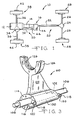
- both the first shift fork assembly 60 and the second shift fork assembly 74 include bodies 100 and 100' which define through, cylindrical internal passageways 102 and 104, respectively, which receive a single shift rail 106.
- the shift rail 106 includes a reduced diameter portion 108 at each end which is received within suitably sized and aligned bores 112 in the housing 48 of the transfer case assembly 16.
- Adjacent the through cylindrical passageway 102 and disposed at each end face of the body 100 of the shift fork assembly 60 is a helical cam 114.
- An axial discontinuity 116 extends between the axially separated ends of helical cams 114 and provides a shoulder or stop.
- the helical cams 114 are engaged by a complementarily configured and spaced apart pair of cam followers 118.
- the cam followers 118 are rollers freely rotatably and axially captively mounted upon a respective pair of mounting pins 120 extending radially from the shift rail 106.
- Fixed pins (followers) without rollers, may, however, also be utilized.
- the shift fork assembly 60 also includes a generally radially extending web 122 and a semi-circular fork 124 having a semi-circular channel 126 which engages the circular flange 58 of the first dog clutch 56.
- the second shift fork assembly 74 is similar to the first shift fork assembly 60, but rather than including two helical cam surfaces 114, its body 100' includes a single helical cam surface 134 and an axial discontinuity 136 which are engaged by a single cam roller or follower 118 rotatably supported upon a mounting pin 120.
- This configuration provides only uni-directionally driven translation of the second shift fork assembly 74 by the shift rail 106.
- Axial translation of the shift fork assembly 74 in the opposite direction is provided by a compression spring 138 disposed concentrically about the shift rail 106 between the second shift fork assembly 74 and a portion of the housing 48.
- Rotation of the shift rail 106 is achieved by a drive assembly 150 comprising a bi-directional electric motor 152 having a worm gear output 154 which drives a complementarily configured gear 156 which directly drives and bi-directionally rotates the shift rail 106.
- a drive assembly 150 comprising a bi-directional electric motor 152 having a worm gear output 154 which drives a complementarily configured gear 156 which directly drives and bi-directionally rotates the shift rail 106.
- an integrated cam and shift fork assembly of either the first configuration described above as the first shift fork assembly 60 having a pair of spaced-apart cam followers 118 cooperating with complementarily spaced-apart helical cams 114 or the second configuration described above as the second shift fork assembly 74 having a single helical cam 134, cam follower 118, and a compression spring 138 disposed adjacent the body 100' of the shift fork assembly 74 are also suited for use in mechanical devices other than transfer cases.
- the first shift fork assembly 60 and the second shift fork assembly 74 may be utilized in motor vehicle transmissions and other power distribution devices.
- the first shift fork assembly 60 and the second shift fork assembly 74 may be utilized with pneumatic or a hydraulic drive systems in addition to the electric motor 152 described above.
Landscapes
- Engineering & Computer Science (AREA)
- General Engineering & Computer Science (AREA)
- Mechanical Engineering (AREA)
- Arrangement And Driving Of Transmission Devices (AREA)
- Gear-Shifting Mechanisms (AREA)
Claims (9)
- Integrierte Nocken- und Schaltgabeleinheit für ein Verteilergetriebe u.ä., die in Kombination umfaßt:gekennzeichnet durcheine Schaltschiene (106), die drehbar um ihre Achse angeordnet ist,einen ersten Nockenfolger (118) der an der Schaltschiene befestigt ist, undeine Schaltgabeleinheit (60), die drehbar die Schaltschiene (106) aufnimmt und eine Schaltgabel (124), die mit einem Kupplungselement (56) in Eingriff treten und dieses bidirektional bewegen kann, und einen ersten Nocken (114) aufweist, der mit dem ersten Nockenfolger (118) in Eingriff steht,
einen bidirektionalen Motor (152),
einen zweiten Nockenfolger (118), der an der Schaltschiene (106) befestigt und im Abstand vom ersten Nokkenfolger (118) angeordnet ist, und
einen zweiten Nocken (114), der mit dem zweiten Nockenfolger (118) in Eingriff steht und im Abstand vom ersten Nocken (114) angeordnet ist. - Integrierte Nocken- und Schaltgabeleinheit nach Anspruch 1, bei der zwei der Schaltgabeleinheiten (60,74) auf einer einzigen rotierenden Schaltschiene (106) angeordnet sind.
- Integrierte Nocken- und Schaltgabeleinheit nach Anspruch 1 oder 2, bei der der Nocken eine Schulter (116) umfaßt, die axial verschobene Abschnitten des Nockens verbindet.
- Integrierte Nocken- und Schaltgabeleinheit nach einem der vorangehenden Ansprüche, bei der die Schaltgabel ein Kanal (126) ist.
- Integrierte Nocken- und Schaltgabeleinheit nach einem der Ansprüche 1 - 3, bei der die Schaltgabel ein Vorsprung (72) ist.
- Integrierte Nocken- und Schaltgabeleinheit nach einem der vorangehenden Ansprüche, die desweiteren ein Verteilergetriebe (16) mit Planetengetriebeantriebseinheit (52) umfaßt, wobei das Kupplungselement so ausgebildet ist, daß es einen Direktantrieb und einen Antrieb mit reduzierter Drehzahl wählt, und die Schaltgabeleinheit mit einer Klauenkupplung (56) in Eingriff steht.
- Integrierte Nocken- und Schaltgabeleinheit nach einem der vorangehenden Ansprüche, bei der die Nockenfolger jeweils eine Rolle (118) umfassen, die an einem Stift (120) gelagert ist.
- Integrierte Nocken- und Schaltgabeleinheit nach einem der vorangehenden Ansprüche, bei der der bidirektionale Motor (152) über einen Drehzahlreduziermechanismus (154, 156) mit der Schaltschiene (106) verbunden ist.
- Integrierte Nocken- und Schaltgabeleinheit nach einem der vorangehenden Ansprüche, die desweiteren eine Kraftaufbringungseinrichtung (156) umfaßt, welche an einem gegenüberliegenden Ende der Schaltgabeleinheit vom ersten Nockenfolger angeordnet ist und die Schaltgabeleinheit in Richtung auf den ersten Nockenfolger (118) antreiben kann.
Applications Claiming Priority (2)
| Application Number | Priority Date | Filing Date | Title |
|---|---|---|---|
| US178125 | 1998-10-23 | ||
| US09/178,125 US6173624B1 (en) | 1998-10-23 | 1998-10-23 | Integrated cam and shift fork assembly |
Publications (2)
| Publication Number | Publication Date |
|---|---|
| EP0997672A1 EP0997672A1 (de) | 2000-05-03 |
| EP0997672B1 true EP0997672B1 (de) | 2003-12-17 |
Family
ID=22651309
Family Applications (1)
| Application Number | Title | Priority Date | Filing Date |
|---|---|---|---|
| EP99308194A Expired - Lifetime EP0997672B1 (de) | 1998-10-23 | 1999-10-18 | Schaltgabel mit eingebauten Nockenbetätigung |
Country Status (5)
| Country | Link |
|---|---|
| US (1) | US6173624B1 (de) |
| EP (1) | EP0997672B1 (de) |
| JP (1) | JP2000170910A (de) |
| KR (1) | KR100648387B1 (de) |
| DE (1) | DE69913641T2 (de) |
Families Citing this family (37)
| Publication number | Priority date | Publication date | Assignee | Title |
|---|---|---|---|---|
| US6341680B1 (en) * | 1997-09-13 | 2002-01-29 | Honda Giken Kogyo Kabushiki Kaisha | Electric-power-assist transmission and its control method |
| JP3689287B2 (ja) * | 1999-10-18 | 2005-08-31 | 本田技研工業株式会社 | トランスミッションの変速装置 |
| DE10020451C1 (de) * | 2000-04-26 | 2001-10-25 | Daimler Chrysler Ag | Schaltvorrichtung für ein Zahnräderwechselgetriebe |
| DE10392239T5 (de) * | 2002-01-25 | 2005-02-24 | Nsk Ltd. | Elektrisches Betätigungsglied |
| KR100475834B1 (ko) | 2002-11-18 | 2005-03-21 | 다이모스(주) | 4륜 구동차량용 부변속기의 전기식 변속장치 |
| US6941833B2 (en) * | 2003-02-12 | 2005-09-13 | Borgwarner Inc. | Shift assembly for a single fork shift assembly |
| US6837819B2 (en) * | 2003-02-18 | 2005-01-04 | Borgwarner Inc. | Transfer case with two planetary gear sets having a common carrier |
| US6802794B2 (en) * | 2003-02-21 | 2004-10-12 | Borgwarner, Inc. | Single actuator lost motion shift assembly |
| AT7355U1 (de) * | 2003-09-30 | 2005-02-25 | Magna Drivetrain Ag & Co Kg | Planetengetriebe mit verschiebbarem kuppelelement und aktuator |
| US6905436B2 (en) * | 2003-10-30 | 2005-06-14 | Magna Drivetrain Of America, Inc. | Two-speed transfer case with adaptive clutch control |
| US6929577B2 (en) * | 2003-11-24 | 2005-08-16 | Magna Drivetrain Of America, Inc. | Clutch actuation system for two-speed active transfer case |
| US7399251B2 (en) * | 2003-11-24 | 2008-07-15 | Magna Powertrain Usa, Inc. | Two-speed transfer case |
| US7435199B2 (en) * | 2004-06-12 | 2008-10-14 | Borgwarner, Inc. | Transfer case with forward hydraulic clutch |
| AT8636U1 (de) * | 2005-04-28 | 2006-10-15 | Magna Drivetrain Ag & Co Kg | Verteilergetriebe für kraftfahrzeuge mit einer gesteuerten reibungskupplung |
| US7540820B2 (en) * | 2005-09-01 | 2009-06-02 | Magna Powertrain Usa, Inc. | Two-speed transfer case with ballramp clutch actuator |
| US20070175286A1 (en) * | 2006-01-27 | 2007-08-02 | Borgwarner Inc. | Electric shift transfer case |
| US7650808B2 (en) | 2006-02-03 | 2010-01-26 | Magna Powertrain Usa, Inc. | Sprial cam clutch actuation system for two-speed transfer case |
| US7694598B2 (en) * | 2006-04-26 | 2010-04-13 | Magna Powertrain Ag & Co Kg | Two-speed transfer case with adaptive torque transfer clutch |
| US20090250309A1 (en) * | 2006-07-31 | 2009-10-08 | Dumitru Puiu | Hydraulic Shift System for Power Transfer Devices |
| JP2009197823A (ja) * | 2008-02-19 | 2009-09-03 | Yamaha Motor Co Ltd | 電子制御式変速装置およびそれを備えた鞍乗型車両 |
| DE102008031815B4 (de) * | 2008-06-25 | 2019-05-16 | GETRAG B.V. & Co. KG | Schaltanordnung für ein Kraftfahrzeuggetriebe |
| DE202009007977U1 (de) * | 2008-10-13 | 2010-02-25 | Magna Powertrain Ag & Co Kg | Kupplung |
| KR101095719B1 (ko) * | 2008-12-11 | 2011-12-21 | 현대모비스 주식회사 | 듀얼클러치 변속기의 변속장치 |
| KR101053528B1 (ko) * | 2008-12-30 | 2011-08-03 | 현대다이모스(주) | 차량의 풀타임 4륜 구동장치 |
| US8156837B2 (en) * | 2009-03-16 | 2012-04-17 | Eaton Corporation | Multiple-ratio transmission with concentric offset shift forks |
| US8516916B2 (en) * | 2009-06-16 | 2013-08-27 | Marine Canada Acquisition Inc. | Linear actuator |
| WO2014131411A1 (de) * | 2013-02-27 | 2014-09-04 | Schaeffler Technologies Gmbh & Co. Kg | Betätigungseinrichtung für ein kraftfahrzeug |
| EP2886911B1 (de) | 2013-12-20 | 2016-08-03 | BorgWarner Inc. | Federbelastete Schaltaktuatoranordnung mit Haltemechanismus |
| US9803731B2 (en) | 2014-04-24 | 2017-10-31 | American Axle & Manufacturing, Inc. | Actuator device having cam and follower and controller configured to employ rate-based methodology to identify positioning of follower on cam at predetermined location |
| DE102015012348A1 (de) * | 2015-09-22 | 2017-03-23 | Daimler Ag | Schaltgabel |
| US9964160B2 (en) * | 2016-02-12 | 2018-05-08 | Borgwarner Inc. | Actuator mechanism for transfer case |
| CN106958627B (zh) * | 2017-04-27 | 2023-09-12 | 重庆康昌机械制造有限公司 | 高性能新能源电动多档变速器 |
| US10500952B2 (en) | 2017-11-20 | 2019-12-10 | Borgwarner Inc. | Transfer case having an actuator assembly with cam follower that is molded into a plastic actuator structure |
| CN110296194B (zh) * | 2019-07-01 | 2022-05-31 | 重庆大学 | 一种行星式三挡换挡装置 |
| DE102020117078A1 (de) * | 2020-06-29 | 2021-12-30 | Schaeffler Technologies AG & Co. KG | Zwei-Gang-Getriebe für ein elektrisch angetriebenes Kraftfahrzeug; sowie Kraftfahrzeug |
| KR102608970B1 (ko) * | 2021-09-07 | 2023-12-06 | 주식회사 네오오토 | 1축 시프트 메커니즘을 구비하는 변속기 |
| WO2025149173A1 (en) * | 2024-01-12 | 2025-07-17 | Ka Group Ag | Differential lock actuator |
Family Cites Families (20)
| Publication number | Priority date | Publication date | Assignee | Title |
|---|---|---|---|---|
| US2446393A (en) | 1945-06-14 | 1948-08-03 | Eaton Mfg Co | Screw-threaded mechanical movement |
| US2649813A (en) | 1949-07-19 | 1953-08-25 | Dana Corp | Power and manually operated gear shift |
| US3370477A (en) * | 1965-09-20 | 1968-02-27 | Power Flo Products Inc | Shifting mechanism |
| JPS5559020A (en) | 1978-10-24 | 1980-05-02 | Aisin Seiki Co Ltd | Power distributer for vehicle |
| US4449416A (en) | 1981-09-04 | 1984-05-22 | J. I. Case Company | Transmission control system |
| JPS5940048A (ja) | 1982-08-31 | 1984-03-05 | Fuji Heavy Ind Ltd | オ−トクラツチ車の変速操作機構 |
| DE3732811A1 (de) | 1986-09-30 | 1988-04-28 | Aisin Seiki | Drehkraft-uebertragungsvorrichtung fuer ein fahrzeug mit vierradantrieb |
| US4790204A (en) | 1987-07-16 | 1988-12-13 | Automotive Products, Plc | Electric shift apparatus |
| US5205179A (en) | 1990-07-21 | 1993-04-27 | Ina Walzlager Schaeffler Kg | Speed changing device |
| EP0481168A1 (de) * | 1990-07-21 | 1992-04-22 | INA Wälzlager Schaeffler KG | Schaltvorrichtung |
| US5159847A (en) | 1991-09-12 | 1992-11-03 | New Venture Gear, Inc. | Sector plate for transfer case |
| DE69302217T2 (de) * | 1992-06-10 | 1996-11-14 | Honda Motor Co Ltd | Verfahren zum Steuern eines Fahrzeuggetriebes |
| US5407024A (en) | 1992-06-24 | 1995-04-18 | Borg-Warner Automotive, Inc. | On demand vehicle drive system |
| US5363938A (en) | 1993-03-09 | 1994-11-15 | New Venture Gear, Inc. | Power transfer system for a four-wheel drive vehicle |
| US5409429A (en) * | 1993-07-30 | 1995-04-25 | Borg-Warner Automotive, Inc. | Transfer case for four wheel drive vehicles |
| US5499951A (en) | 1993-08-02 | 1996-03-19 | Borg-Warner Automotive, Inc. | Dynamic range shift transfer case with electromagnetic clutch for coupling one output to the input for modulating torque split |
| US5492194A (en) | 1993-12-23 | 1996-02-20 | Borg-Warner Automotive, Inc. | On demand vehicle drive system |
| US5460060A (en) | 1994-07-27 | 1995-10-24 | Eaton Corporation | Transmission shifting mechanism with spring loaded ball screw |
| DE19516651A1 (de) * | 1995-05-05 | 1996-11-07 | Bayerische Motoren Werke Ag | Schaltgetriebe |
| US5740695A (en) * | 1996-01-29 | 1998-04-21 | Ford Global Technologies, Inc. | Shift device for a manual transmission |
-
1998
- 1998-10-23 US US09/178,125 patent/US6173624B1/en not_active Expired - Fee Related
-
1999
- 1999-10-18 DE DE69913641T patent/DE69913641T2/de not_active Expired - Lifetime
- 1999-10-18 EP EP99308194A patent/EP0997672B1/de not_active Expired - Lifetime
- 1999-10-20 JP JP11297947A patent/JP2000170910A/ja active Pending
- 1999-10-22 KR KR1019990045968A patent/KR100648387B1/ko not_active Expired - Fee Related
Also Published As
| Publication number | Publication date |
|---|---|
| KR100648387B1 (ko) | 2006-11-24 |
| EP0997672A1 (de) | 2000-05-03 |
| KR20000029251A (ko) | 2000-05-25 |
| DE69913641D1 (de) | 2004-01-29 |
| US6173624B1 (en) | 2001-01-16 |
| JP2000170910A (ja) | 2000-06-23 |
| DE69913641T2 (de) | 2004-06-09 |
Similar Documents
| Publication | Publication Date | Title |
|---|---|---|
| US6173624B1 (en) | Integrated cam and shift fork assembly | |
| US5992592A (en) | Bi-directional overrunning clutch assembly for transfer cases and the like | |
| US5159847A (en) | Sector plate for transfer case | |
| US5584776A (en) | Transfer case having parallel clutches and lockup feature | |
| US4770280A (en) | Snap-action arrangement for transfer case synchronizer | |
| EP0882912B1 (de) | Betätigungsvorrichtung für eine einzelne Schaltstange | |
| US6846262B2 (en) | Transfer case shift system for controllable bi-directional overrunning clutch | |
| US6230577B1 (en) | Electric shift control assembly | |
| US6814682B2 (en) | Transfer case with synchronizer clutch | |
| US6367344B1 (en) | Integrated motor and electronic controller | |
| US5718653A (en) | Differential assembly for transfer cases and vehicle drivelines | |
| US5833566A (en) | Speed reduction assembly with full disconnect for transfer cases and the like | |
| US5984821A (en) | Transfer case with four-wheel underdrive operating mode | |
| US6251045B1 (en) | Method and apparatus for providing synchronization of low to high shifts in a transfer case | |
| US6620073B2 (en) | Driving force transmitting device for vehicle | |
| US5620072A (en) | Transfer case having disc pack and cone clutch | |
| US20040188212A1 (en) | Electromagnetic clutch having ball ramp actuator and torsion spring | |
| KR20040075684A (ko) | 싱글 액추에이터 로스트 모션 시프트 조립체 | |
| US6033334A (en) | Transfer case having speed proportional clutch | |
| JPH11125280A (ja) | トランスファーケース等用の磁気−流動学的作動装置を持つクラッチ | |
| CA2584588A1 (en) | Two-speed transfer case with adaptive torque transfer clutch | |
| US3908775A (en) | Transfer case assembly with a double duty differential | |
| US20130263684A1 (en) | Shift system for power transfer unit having dual sector shift actuator | |
| US4545456A (en) | Four-wheel drive axleshaft clutch mechanism | |
| SU1082638A1 (ru) | Самоблокирующийс дифференциал транспортного средства |
Legal Events
| Date | Code | Title | Description |
|---|---|---|---|
| PUAI | Public reference made under article 153(3) epc to a published international application that has entered the european phase |
Free format text: ORIGINAL CODE: 0009012 |
|
| AK | Designated contracting states |
Kind code of ref document: A1 Designated state(s): DE GB |
|
| AX | Request for extension of the european patent |
Free format text: AL;LT;LV;MK;RO;SI |
|
| 17P | Request for examination filed |
Effective date: 20000929 |
|
| AKX | Designation fees paid |
Free format text: DE GB |
|
| 17Q | First examination report despatched |
Effective date: 20021029 |
|
| GRAH | Despatch of communication of intention to grant a patent |
Free format text: ORIGINAL CODE: EPIDOS IGRA |
|
| RAP1 | Party data changed (applicant data changed or rights of an application transferred) |
Owner name: BORGWARNER, INC. |
|
| GRAS | Grant fee paid |
Free format text: ORIGINAL CODE: EPIDOSNIGR3 |
|
| GRAA | (expected) grant |
Free format text: ORIGINAL CODE: 0009210 |
|
| AK | Designated contracting states |
Kind code of ref document: B1 Designated state(s): DE GB |
|
| REG | Reference to a national code |
Ref country code: GB Ref legal event code: FG4D |
|
| REF | Corresponds to: |
Ref document number: 69913641 Country of ref document: DE Date of ref document: 20040129 Kind code of ref document: P |
|
| PLBE | No opposition filed within time limit |
Free format text: ORIGINAL CODE: 0009261 |
|
| STAA | Information on the status of an ep patent application or granted ep patent |
Free format text: STATUS: NO OPPOSITION FILED WITHIN TIME LIMIT |
|
| 26N | No opposition filed |
Effective date: 20040920 |
|
| PGFP | Annual fee paid to national office [announced via postgrant information from national office to epo] |
Ref country code: GB Payment date: 20080915 Year of fee payment: 10 |
|
| PG25 | Lapsed in a contracting state [announced via postgrant information from national office to epo] |
Ref country code: GB Free format text: LAPSE BECAUSE OF NON-PAYMENT OF DUE FEES Effective date: 20091018 |
|
| PGFP | Annual fee paid to national office [announced via postgrant information from national office to epo] |
Ref country code: DE Payment date: 20101029 Year of fee payment: 12 |
|
| PG25 | Lapsed in a contracting state [announced via postgrant information from national office to epo] |
Ref country code: DE Free format text: LAPSE BECAUSE OF NON-PAYMENT OF DUE FEES Effective date: 20130501 |
|
| REG | Reference to a national code |
Ref country code: DE Ref legal event code: R119 Ref document number: 69913641 Country of ref document: DE Effective date: 20130501 |