EP0997680B1 - Dispositif de fixation - Google Patents
Dispositif de fixation Download PDFInfo
- Publication number
- EP0997680B1 EP0997680B1 EP99115650A EP99115650A EP0997680B1 EP 0997680 B1 EP0997680 B1 EP 0997680B1 EP 99115650 A EP99115650 A EP 99115650A EP 99115650 A EP99115650 A EP 99115650A EP 0997680 B1 EP0997680 B1 EP 0997680B1
- Authority
- EP
- European Patent Office
- Prior art keywords
- adapter
- arrangement according
- fastening arrangement
- wall
- Prior art date
- Legal status (The legal status is an assumption and is not a legal conclusion. Google has not performed a legal analysis and makes no representation as to the accuracy of the status listed.)
- Expired - Lifetime
Links
- 239000012530 fluid Substances 0.000 claims description 21
- 238000007789 sealing Methods 0.000 claims description 11
- 239000003566 sealing material Substances 0.000 claims description 3
- 230000007704 transition Effects 0.000 claims description 3
- 230000003750 conditioning effect Effects 0.000 claims 1
- 238000012423 maintenance Methods 0.000 description 6
- 238000013461 design Methods 0.000 description 4
- 238000003780 insertion Methods 0.000 description 3
- 230000037431 insertion Effects 0.000 description 3
- 238000013459 approach Methods 0.000 description 2
- 238000009434 installation Methods 0.000 description 2
- 238000004519 manufacturing process Methods 0.000 description 2
- 239000000463 material Substances 0.000 description 2
- NJPPVKZQTLUDBO-UHFFFAOYSA-N novaluron Chemical compound C1=C(Cl)C(OC(F)(F)C(OC(F)(F)F)F)=CC=C1NC(=O)NC(=O)C1=C(F)C=CC=C1F NJPPVKZQTLUDBO-UHFFFAOYSA-N 0.000 description 2
- 238000011144 upstream manufacturing Methods 0.000 description 2
- 229910000831 Steel Inorganic materials 0.000 description 1
- 230000009286 beneficial effect Effects 0.000 description 1
- 230000000295 complement effect Effects 0.000 description 1
- 230000002950 deficient Effects 0.000 description 1
- 238000011161 development Methods 0.000 description 1
- 230000018109 developmental process Effects 0.000 description 1
- 239000013013 elastic material Substances 0.000 description 1
- 230000001771 impaired effect Effects 0.000 description 1
- 230000013011 mating Effects 0.000 description 1
- 239000002245 particle Substances 0.000 description 1
- 230000002093 peripheral effect Effects 0.000 description 1
- 230000001105 regulatory effect Effects 0.000 description 1
- 239000007787 solid Substances 0.000 description 1
- 239000010959 steel Substances 0.000 description 1
- 230000008719 thickening Effects 0.000 description 1
- 238000012546 transfer Methods 0.000 description 1
Images


Classifications
-
- G—PHYSICS
- G01—MEASURING; TESTING
- G01L—MEASURING FORCE, STRESS, TORQUE, WORK, MECHANICAL POWER, MECHANICAL EFFICIENCY, OR FLUID PRESSURE
- G01L19/00—Details of, or accessories for, apparatus for measuring steady or quasi-steady pressure of a fluent medium insofar as such details or accessories are not special to particular types of pressure gauges
- G01L19/0007—Fluidic connecting means
Definitions
- DE 28 49 133 discloses a connecting device for pressure lines, in which a plug-type connection piece can be inserted into a housing opening of a housing provided for this purpose.
- the connector has a plug-in pin on the upper portion of a circumferential groove is formed, which is followed by a circumferential approach, which serves as a stop and predetermines the insertion depth of the connector into the opening of the housing.
- To lock the connector is a base plate having a rail-shaped receptacle for acting as a bolt, in the rail-shaped receptacle reciprocally movable slide.
- the slider in turn has at least one key-shaped opening with an approximately circular portion whose opening diameter corresponds to the diameter of the housing opening and a portion opposite this narrowed. If the connector is inserted with its plug-in pin in the associated housing opening, the slider is moved from the position in which its large diameter portion is aligned with the housing opening, such that the narrowed portion engages with its edges in the groove tangent to the pin, so that the connector is locked and can not be pulled out of the housing opening again. In the locked position, the approach is on the pin in a pocket-like receptacle, which is bounded on the one hand by the top of the housing and on the other hand by the underside of the slider, wherein the adjacent to the stop groove passes through the narrowed portion of the slider.
- the compressed air is filtered, for example, with Oil particles offset or to a desired working pressure regulated.
- the set working pressure can be at a Read off the manometer, as an additional part of an example mounted as a filter-controller device running maintenance device is.
- a fastening device contains the threaded connection fixed to a pressure gauge, in a provided on the service unit threaded hole is screwed, which acts on the pressure to be measured (see Deppert / Stoll "Pneumatic Controls", 10th Edition 1994, pages 38 to 47).
- the assembly and disassembly of the known pressure gauges is relative cumbersome and often leads to unwanted alignments of the manometer, which is a convenient reading of the displayed Prevent pressure values.
- the rotational position of the manometer depends on the possible screw-in depth of the threaded neck which may vary from case to case, so in the final assembly state present orientation usually more random is.
- Another disadvantage is that in an example defective replacement of the manometer the threaded connection to be solved in a complicated way, where not rarely damage to the thread mating occur, in particular if previously corrosive material attacks occurred are. Under certain circumstances, this will make the entire maintenance unit unusable.
- a fastening device for attaching an additional part to a Main body to create, with reduced risk of damage allows easier handling.
- the fastening device is characterized characterized in that the clamping part as with respect to the front Pocket wall separate component is formed, which is to Position the assembly final condition in the receiving pocket in this way lets it be on both sides of the pedestal between the Retaining flange and provided on the additional part, front pocket wall intervenes.
- the additional part may in particular by a measuring and / or display device, for example, a pressure sensor or a pressure gauge, be formed.
- the main part may be in particular to a fluid-carrying device, for example a act for the preparation of compressed air serving maintenance device.
- the attachment of the additional part to the main part takes place with interposition an adapter, which may be an integral part of the main part can, but expediently as a separate component is executed.
- the separate embodiment has the advantage that not different accessories with different Terminal sizes are produced or stored have to.
- One and the same accessory can thus easily to be grown to different main parts, it is just to choose another adapter, its structure and Production is easy.
- He has a spaced arranged to the associated body Holding flange on which the attachment with his as Receiving bag designated pocket-like recess put on until either the edge of the retaining flange or the peripheral surface of the base rests on the additional part and thereby limits the Aufsteckweg.
- Mounting intermediate position can be the additional part with appropriate design of the adapter angularly in a desired orientation, whereupon by pressing the clamping part of the final assembly state is produced, in which the attachment firmly is fixed to the adapter.
- the clamping part engages its fork-like clamping section on each other diametrically opposite sides of the socket between the retaining flange and the recess limiting component the front pocket wall, wherein the retaining flange in Direction of the rear pocket wall is pressed and up overall gives a firm deadlock.
- the adapter is expediently designed as a screw, wherein the base provided with an external thread that can be in one with a complementary one Screw in threaded connection opening of the main part leaves.
- the external thread can with a suitable Sealing material should be coated to automatically when screwing a fluid-tight connection between adapter and Manufacture screw. Is an exchange of the additional part This may be necessary after removing the clamp be removed from the adapter, the adapter on Main body can remain and thus the tightness and Functionality of the threaded connection not impaired becomes.
- the fluid supply to the additional part takes place expediently via a particular coaxial adapter passing through passageway.
- the adapter has a multiple function to hold the Additional part and for guiding the relevant fluid.
- an existing rubber-elastic material placed, preferably in an annular groove of the rear pocket wall of the additional part and / or the adapter.
- the sealing ring can as required have any shapes, including other geometries than a circular geometry are used can reach.
- Optimal twistability and thus variable rotational positioning of the additional part with respect to the adapter results when the retaining flange is over a circular Outside outline has, so to speak, a guide for the rotational movement forms.
- the adapter can also be laterally on the boundary surface support the recess. Especially in this Case can be the receiving pocket at the pocket opening opposite side also be completely open.
- the clamping part can be designed like a slide and in the frame a sliding movement between an assembly and Dismantling of the additional part enabling release and one defining the final assembly state of the additional part Clamping be brought. It can if necessary be stored on the additional part that it is also in the Release position is captively fixed. It is possible but also, the clamping part as a completely separate component in the release position of the additional part is removed and only to obtain the clamping position on Attachment is attached.
- the main part 1 maintenance device shown in compressed air networks for the treatment of Compressed air is used. It concerns in the present Case to a combined filter-controller unit, in the Among other things, the pressure of the compressed air from one by one Pressure source provided output pressure to a lower Working pressure is adjusted.
- the under the Working pressure standing compressed air is among other things in a first fluid channel 2, which via a with a Internally threaded connection opening 3 to the outer surface of the housing of the main part 1 opens.
- the manometer serves to the prevailing in the first fluid channel 2 To record or measure working pressure and a Display device 5 to bring to the display.
- a Display device 5 to bring to the display.
- the manometer serves to the prevailing in the first fluid channel 2 To record or measure working pressure and a Display device 5 to bring to the display.
- the pressure sensor 7 is in the embodiment Part of a fixed in the housing 8 of the additional part 4
- Printed circuit board 12 to which the example with LED and / or display device equipped with LCD display means 5 is connected. At her can be in the present Case read the pressure values of the working pressure.
- An additional electrical connection device 13 can be provided to connect the pressure gauge to an external display and / or control device to connect.
- the generally designated by reference numeral 14 fastening device is particularly suitable for installation a measuring and / or display device on a fluid-carrying Device, for example on a so-called maintenance device. It goes without saying, however, that she is also responsible for mutual attachment of any other parts used can be.
- the fastening device 14 includes a following simplifies only as an adapter 15 designated adapter part, the expediently as with respect to the main part 1 separate Part is executed and in particular solvable on Set body 1. In principle, it would also be one-piece Design with the main part 1 possible, what but at the expense of universal applications would go, so that the separate execution is preferred.
- the adapter 15 has a socket-like base 16, at its one axial end portion in one piece Retaining flange 17 is formed.
- the retaining flange 17 has suitably an annular shape and is coaxial aligned to the base 16, wherein it is radially around the side protrudes beyond the base 16.
- On the base facing away Axial side he defined together with the socket a substantially disc-like contact surface 18, the is axially oriented.
- the base 16 is equipped with connecting means which allow a firm connection with the main body 1. she exist in the embodiment of an external thread 19, so that the adapter 15 is a screw part as a whole and with its base 16 in the connection opening 3 of the Main body 1 screwed tight.
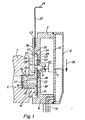
- Fig. 3 has the retaining flange 17 over a circular outer contour. Nevertheless a tight screwing into the connection opening 3 to allow is in the adapter 15, starting from the Bearing surface 18 concentrically a recess 22 introduced which is contoured as a polygon socket and plugging or applying a suitable screwing tool allowed.
- the additional part 4 can be mounted on the main body 1, that its rear side faces the main part 1. in the Area of this back is one with it for simplification as a receiving pocket 23 designated bag-like Well provided, the pocket opening 24 at mounted additional part 4 viewed transversely to the longitudinal axis 25 of the Adapters 15 is oriented.
- FIG. 2 shows the additional part 4 in the finished on the main part. 1 assembled state, what follows as final assembly state is designated. Visible here is the pocket opening 24 perpendicular to the longitudinal axis 25 of the adapter 15 or its base 16 aligned.
- the receiving pocket 23 has one of the rear wall 26 of the additional part 4 formed rear pocket wall 27 and one of these, seen in final assembly state, at a distance in Direction to bulk 1 upstream front pocket wall 28.
- the pocket interior 32 facing inner surface 34 of the lateral pocket wall 33 is at least in the pocket opening 24 directly opposite Area contoured circular arc, wherein the Pocket opening 24 out even with a linear course can, so seen in cross section a suitably U-shaped course of the side pocket wall 33 provided inner surface 34 results.
- the rear wall 26 is extended beyond the pocket opening 24, wherein the pocket opening 24 upstream Area forms a second contact surface 18 '. Further is the height h of the pocket opening 24 is chosen to be slightly larger than the thickness of the retaining flange 17th
- the front pocket wall 28 has an edge to the Pocket opening 24 toward open recess 35, which in the embodiment is contoured circular arc and a Cross-section, which is an at least partial insertion the base 16 allows.
- first Mounting step in the region of the second contact surface 18 'with its rear wall 26 to the provided on the adapter 15 first Investment surface 18 is laid out substantially flat. This condition is shown in Fig. 1.
- the adapter 15 is here with its retaining flange 17 of the pocket opening 24 opposite.
- the additional part 4 according to arrow 36 across the Longitudinal axis 25 of the adapter 15 is displaced and with its receiving pocket 23 attached to the retaining flange 17.
- the retaining flange 17 now projects according to FIGS. 2 and 3 with a part of its circumference, for example with something more than half the circumference, in the pocket interior 32 into it, at the same time the base 16 in the recess 35 intervenes and enforces them.
- the additional part 4 is now practically attached to the adapter 15, wherein the corresponding position referred to as intermediate mounting position be.
- the slip is specified and limited by that the retaining flange 17 with its edge on the inner surface 34th the lateral pocket wall 33 of the receiving pocket 23 for Plant passes, as can be seen from Fig. 2 and 3. There is then still the advantageous possibility, the Additional part 4 relative to the adapter 15 with respect to Twist longitudinal axis 25 and angularly in the desired Align the end position, the aforementioned Inner surface 34 on the radially outward-facing edge slides along the retaining flange 17.
- a clamping part 37 of the fastening device 14 used.
- This clamping part 37 is in the embodiment designed slide-like and can be insert from the outside into a slot-like opening 38, the lateral pocket wall 33 in which the Pocket opening 24 passes through opposite area, and on the one hand to the pocket interior 32 and the other to the outer surface of the housing 8 of the additional part 4 is open.
- the expansion plane of the slot-like opening 38 runs parallel to that of the pocket interior 32, wherein the pocket interior 32 facing the mouth 42 of the opening 38 expediently immediately is provided in addition to the front pocket wall 28.
- the clamping member 37 is in the embodiment as with respect executed the additional part 4 separate component and is expediently in mounting intermediate position befindliches additional part 4 from the outside into the slot-like Opening 38 inserted and inserted so far that it projects into the receiving pocket 23 and with a provided at the front end portion clamping portion 43 between the retaining flange 17 and the front pocket wall 28 comes to rest.
- the clamping part 37 enters the resulting from Fig. 2 and 3 clamping position, in the it is between the retaining flange 17 and the front Pocket wall 28 is supported and at the same time the retaining flange 17 presses against the rear wall of the bag, so that the additional part 4 fixed to the retaining flange 17 of the adapter 15 is clamped or jammed.
- the desired clamping force can be influenced by the thickness of the Clamping portion 43 and the retaining flange 17 so each other votes that the sum of the thickness dimensions a certain degree is greater than the height h of the pocket interior, so that a solid, non-positive connection established. It can be ensured that the Additional part 4 even in the final assembly state, at least slightly rotates relative to the adapter 15 to a Fine adjustment to obtain the desired orientation.
- the clamping portion 43 is fork-shaped and has over two spaced apart parallel Fork arms 44, 44 ', which in the final assembly state on each other diametrically opposite circumferential sides of the base 16 to come to rest and embrace the pedestal practically rider-like. You could also think of a bow-shaped design speak the clamping section 43.
- actuating part 46 facilitates the sliding operation of the clamping part 37 both when pushing into the receiving pocket 23 as even when later pulling out when the additional part. 4 should be removed again. This is special recommended if the actuator section 46 angled is such that the end portion has an L-like shape, wherein the actuating portion 46 at the same time as Stop can serve, the insertion of the clamping part 37 limited by being on the housing 8 of the additional part. 4 runs.
- the adapter 15 When mounted additional part 4 is through the adapter 15th through a fluid connection between the two fluid channels 2, 6 produced.
- the adapter 15 with a particular him coaxially interspersed passageway 47 provided at one end to the first fluid channel 2 facing end face of the base 16 opens and the other end to the first contact surface 18 is open. This Opening is opposite to the opening of the second fluid channel 6, so that the pressure medium from the first fluid channel. 2 across the passageway 47 into the second fluid channel 6 of the additional part 4 can pass.
- the sealing ring 48 has expediently, seen in the axial direction, an annular Geometry, but can also be a if necessary have other ring shape, for example oval or polygonal.
- the arrangement is expediently made in this way that the sealing ring 48 before attaching the additional part 4 to the adapter 15 slightly to the pocket interior 32nd protrudes beyond the rear pocket wall 27, so that he after jamming of the individual components by the Adapter 15 is pressed firmly with the rear wall 26 to to make a good sealing contact.
- the retaining flange 17 by the clamping part 37th with the interposition of the sealing ring 48 against the rear pocket wall 27 is pressed, wherein the retaining flange 17th expediently no direct contact with the rear Pocket wall 27 has, but the support only about the intermediate and elastically deformed sealing ring 48 takes place.
- the sealing ring 48 may otherwise instead of one provided in the rear pocket wall 27 Ring groove 52 in one of the adapter 15 at the rear pocket wall 27 facing side provided Insert ring groove (not shown).
- the clamping part 37 is in particular in the region of fork-like clamping portion 43 and preferably in total made of flat material, for example made of sheet steel.
- slightly modified design can be provided that the lateral pocket wall 33 in which the pocket opening 24 directly opposite area with one over the entire pocket interior height "h" extending aperture is provided so that the receiving pocket 23 in a direction parallel to the direction of attachment 36 direction is open, the adapter 15 with its retaining flange 17 from the side of the pocket opening 24 and the preferably slider-like clamping member 37 through the opposite Opening 38 are inserted therethrough can. Since the aperture 38 in this case in comparison to the present in the embodiment narrow, slit-like opening has a greater height, one is in In this case, the opening 38 passing through Region of the clamping member 37 also thickened accordingly to get a shift guide.
- the Thickening can be provided, for example, by that the clamping part 37 is folded laterally and thereby has tab-like guide projections, with which it can be supported on the wall of the opening 38.
- the slip-on of the additional part 4 expediently limited by that the recess with its curved boundary surface laterally on the outer periphery of the base 16 comes to rest. Since this as the boundary surface of the recess 15 a has curved outer contour is in the plugged state the additional part 4 further with respect to a rotational positioning of the adapter 15 possible.
Landscapes
- Physics & Mathematics (AREA)
- General Physics & Mathematics (AREA)
- Clamps And Clips (AREA)
- Paper (AREA)
- Basic Packing Technique (AREA)
- Seal Device For Vehicle (AREA)
- Insertion Pins And Rivets (AREA)
Claims (17)
- Dispositif de fixation pour la fixation d'une pièce auxiliaire (4) sur une pièce principale (1),avec un adaptateur (15) disposé ou pouvant être fixé sur la pièce principale (1), comportant un socle (16) destiné à la liaison avec la pièce principale (1) et une bride de maintien (17) disposée sur le socle (16) à distance de la pièce principale (1), débordant latéralement du socle (16),avec une poche de réception (23) prévue sur la pièce auxiliaire (4), qui comporte une paroi postérieure de poche (27) et une paroi antérieure de poche (28) opposée à cette dernière à une certaine distance, la paroi antérieure de poche (28) étant pourvue d'un évidement (35) ouvert vers le bord de l'ouverture de la poche (24), pour que la pièce auxiliaire (4) puisse être enfichée d'abord dans une position intermédiaire de montage sur l'adaptateur (15) par l'ouverture de poche (24), dans laquelle la bride de maintien (17) est logée au moins par une partie de sa périphérie à l'intérieur de la poche de réception (23), entre les deux parois de poche (27, 28), et le socle (16) traversant l'évidement (35),et avec un élément de serrage (37) comportant un tronçon de serrage (43) fourchu, qui pour le maintien d'une position finale de montage de la pièce auxiliaire (4) se laisse positionner de façon à passer de part et d'autre du socle et à presser alors la bride de maintien (17) en direction de la paroi postérieure de poche (27), caractérisé en ce quel'élément de serrage (37) est conçu comme un élément séparé par rapport à la paroi antérieure de poche (28), qui pour le maintien de la position finale de montage se laisse positionner dans la poche de réception (23) de façon à s'accrocher des deux côtés du socle (16), entre la bride de maintien (17) et la paroi antérieure de poche (28) prévue sur la pièce auxiliaire (4).
- Dispositif de fixation selon la revendication 1, caractérisé en ce que l'adaptateur (15) est réalisé sous la forme d'une pièce à visser, pouvant être vissée sur la pièce principale (1).
- Dispositif de fixation selon la revendication 2, caractérisé en ce que le socle (16) comporte un filetage extérieur (19) qui est avantageusement revêtu d'une matière d'étanchéité, pour permettre un assemblage étanche par vis sur la pièce principale (1).
- Dispositif de fixation selon la revendication 2 ou 3, caractérisé en ce que l'adaptateur (15) dispose d'un évidement (22) muni de pans creux qui permet de mettre en place un outil de vissage.
- Dispositif de fixation selon l'une des revendications 1 à 4, caractérisé en ce que l'adaptateur (15) dispose d'un canal de passage (47) qui permet une liaison par fluide entre la pièce principale (1) et la pièce auxiliaire (4).
- Dispositif de fixation selon la revendication 5, caractérisé en ce que le canal de passage (47) débouche sur la surface frontale (18) de l'adaptateur (15) qui est opposée au socle (16) et en ce que lorsque la pièce auxiliaire (4) est montée, il communique avec un canal à fluide (6) prévu dans cette dernière.
- Dispositif de fixation selon la revendication 6, caractérisé en ce qu'est prévue une bague d'étanchéité (48) située entre l'adaptateur (15) et la paroi postérieure de poche (27) lorsque la pièce auxiliaire (4) est montée, pour assurer l'étanchéité de la zone de transition entre le canal de passage (47) et le canal à fluide (6), par l'intermédiaire de laquelle la bride de maintien (17) s'appuie avantageusement sur la paroi postérieure de poche (27).
- Dispositif de fixation selon la revendication 7, caractérisé en ce que la bague d'étanchéité (48) est montée dans une rainure annulaire (52) de la pièce auxiliaire (4) et/ou de l'adaptateur (15) entourant l'embouchure du canal à fluide (6) de la pièce auxiliaire (4).
- Dispositif de fixation selon l'une des revendications 1 à 8, caractérisé en ce que la bride de maintien (17) possède un contour extérieur circulaire.
- Dispositif de fixation selon l'une des revendications 1 à 9, caractérisé en ce qu'au moins la zone de la surface intérieure (34) faisant face à l'ouverture de poche (24) de la paroi latérale de poche (33) reliant les parois postérieure et antérieure de poche (27, 28) a un contour circulaire et/ou analogue à un U.
- Dispositif de fixation selon l'une des revendications 1 à 9, caractérisé en ce que la zone de la paroi latérale (33) de la poche de réception (23) reliant les parois postérieure et antérieure de poche (27, 28) faisant face à l'ouverture de poche (24) est ouverte.
- Dispositif de fixation selon l'une des revendications 1 à 11, caractérisé en ce que lorsqu'elle adopte la position intermédiaire de montage et notamment également après atteinte de la position finale de montage, la pièce auxiliaire (4) est rotative par rapport à l'adaptateur (15), par rapport à l'axe longitudinal (25) de ce dernier et peut être positionnée dans différentes positions angulaires.
- Dispositif de fixation selon l'une des revendications 1 à 12, caractérisé en ce que l'élément de serrage (37) est réalisé à la façon d'un coulisseau.
- Dispositif de fixation selon l'une des revendications 1 à 13, caractérisé par un perçage (38) opposé à l'ouverture de poche (24) par exemple sous la forme d'une fente, à travers lequel l'élément de serrage (37) peut saillir dans la poche de réception (23), de façon coulissante par rapport à la pièce auxiliaire (4).
- Dispositif de fixation selon la revendication 14, caractérisé en ce que sur le tronçon d'extrémité de l'élément de serrage (37) saillant hors du perçage (38) sur le côté opposé à la poche de réception (23), est prévue une partie d'actionnement (46) notamment coudée.
- Dispositif de fixation selon l'une des revendications 1 à 15, caractérisé en ce que la pièce auxiliaire (4) est formée par un instrument de mesure et/ou d'affichage, notamment par un capteur de pression ou un manomètre.
- Dispositif de fixation selon l'une des revendications 1 à 16, caractérisé en ce que la pièce principale (1) est formée par une unité conductrice de fluide, notamment par un appareil de maintenance destiné à mettre à disposition de l'air comprimé.
Applications Claiming Priority (2)
| Application Number | Priority Date | Filing Date | Title |
|---|---|---|---|
| DE29819377U DE29819377U1 (de) | 1998-10-30 | 1998-10-30 | Befestigungsvorrichtung |
| DE29819377U | 1998-10-30 |
Publications (3)
| Publication Number | Publication Date |
|---|---|
| EP0997680A2 EP0997680A2 (fr) | 2000-05-03 |
| EP0997680A3 EP0997680A3 (fr) | 2002-03-06 |
| EP0997680B1 true EP0997680B1 (fr) | 2005-10-19 |
Family
ID=8064625
Family Applications (1)
| Application Number | Title | Priority Date | Filing Date |
|---|---|---|---|
| EP99115650A Expired - Lifetime EP0997680B1 (fr) | 1998-10-30 | 1999-08-07 | Dispositif de fixation |
Country Status (2)
| Country | Link |
|---|---|
| EP (1) | EP0997680B1 (fr) |
| DE (2) | DE29819377U1 (fr) |
Cited By (8)
| Publication number | Priority date | Publication date | Assignee | Title |
|---|---|---|---|---|
| US7658196B2 (en) | 2005-02-24 | 2010-02-09 | Ethicon Endo-Surgery, Inc. | System and method for determining implanted device orientation |
| US7775215B2 (en) | 2005-02-24 | 2010-08-17 | Ethicon Endo-Surgery, Inc. | System and method for determining implanted device positioning and obtaining pressure data |
| US7775966B2 (en) | 2005-02-24 | 2010-08-17 | Ethicon Endo-Surgery, Inc. | Non-invasive pressure measurement in a fluid adjustable restrictive device |
| US7927270B2 (en) | 2005-02-24 | 2011-04-19 | Ethicon Endo-Surgery, Inc. | External mechanical pressure sensor for gastric band pressure measurements |
| US8016745B2 (en) | 2005-02-24 | 2011-09-13 | Ethicon Endo-Surgery, Inc. | Monitoring of a food intake restriction device |
| US8016744B2 (en) | 2005-02-24 | 2011-09-13 | Ethicon Endo-Surgery, Inc. | External pressure-based gastric band adjustment system and method |
| US8066629B2 (en) | 2005-02-24 | 2011-11-29 | Ethicon Endo-Surgery, Inc. | Apparatus for adjustment and sensing of gastric band pressure |
| US8870742B2 (en) | 2006-04-06 | 2014-10-28 | Ethicon Endo-Surgery, Inc. | GUI for an implantable restriction device and a data logger |
Families Citing this family (4)
| Publication number | Priority date | Publication date | Assignee | Title |
|---|---|---|---|---|
| DE20308234U1 (de) * | 2003-05-27 | 2003-08-21 | Schwarz Verbindungssysteme GmbH, 75382 Althengstett | Anordnung zur Aufnahme eines lösbar verriegelbaren Einschub-Elementes |
| US8152710B2 (en) | 2006-04-06 | 2012-04-10 | Ethicon Endo-Surgery, Inc. | Physiological parameter analysis for an implantable restriction device and a data logger |
| ES2363951T3 (es) * | 2007-12-24 | 2011-08-19 | Flow Meter S.P.A. | Ensamblaje de succión para uso en el campo médico. |
| DE102008049152A1 (de) | 2008-09-26 | 2010-04-01 | Watts Instrumentation Gmbh | Drehbares Instrumentengehäuse |
Citations (3)
| Publication number | Priority date | Publication date | Assignee | Title |
|---|---|---|---|---|
| GB937393A (en) * | 1961-03-29 | 1963-09-18 | Agfa Ag | Coupling means for the detachable assembly of component parts of apparatus |
| US5577301A (en) * | 1995-06-05 | 1996-11-26 | Prince Corporation | Retainer and locking clip for attaching an accessory to a vehicle |
| FR2738877A1 (fr) * | 1995-09-14 | 1997-03-21 | Le Vetement Des Temps Nouveaux | Dispositif de fixation sur une sangle ou similaire |
Family Cites Families (3)
| Publication number | Priority date | Publication date | Assignee | Title |
|---|---|---|---|---|
| FR1277596A (fr) * | 1961-01-11 | 1961-12-01 | Schneider & Co W | Pince de jonction |
| DE2849133A1 (de) * | 1978-11-13 | 1980-05-29 | Voss Armaturen | Anschlussvorrichtung fuer druckleitungen mit aeusserer verriegelung |
| US5634673A (en) * | 1994-03-29 | 1997-06-03 | Toyoda Gosei Co., Ltd. | Joint device |
-
1998
- 1998-10-30 DE DE29819377U patent/DE29819377U1/de not_active Expired - Lifetime
-
1999
- 1999-08-07 EP EP99115650A patent/EP0997680B1/fr not_active Expired - Lifetime
- 1999-08-07 DE DE59912673T patent/DE59912673D1/de not_active Expired - Lifetime
Patent Citations (3)
| Publication number | Priority date | Publication date | Assignee | Title |
|---|---|---|---|---|
| GB937393A (en) * | 1961-03-29 | 1963-09-18 | Agfa Ag | Coupling means for the detachable assembly of component parts of apparatus |
| US5577301A (en) * | 1995-06-05 | 1996-11-26 | Prince Corporation | Retainer and locking clip for attaching an accessory to a vehicle |
| FR2738877A1 (fr) * | 1995-09-14 | 1997-03-21 | Le Vetement Des Temps Nouveaux | Dispositif de fixation sur une sangle ou similaire |
Non-Patent Citations (1)
| Title |
|---|
| DEPPERT; STOLL: "Pneumatische Steuerungen", 1994, VOGEL, WÜRZBURG * |
Cited By (8)
| Publication number | Priority date | Publication date | Assignee | Title |
|---|---|---|---|---|
| US7658196B2 (en) | 2005-02-24 | 2010-02-09 | Ethicon Endo-Surgery, Inc. | System and method for determining implanted device orientation |
| US7775215B2 (en) | 2005-02-24 | 2010-08-17 | Ethicon Endo-Surgery, Inc. | System and method for determining implanted device positioning and obtaining pressure data |
| US7775966B2 (en) | 2005-02-24 | 2010-08-17 | Ethicon Endo-Surgery, Inc. | Non-invasive pressure measurement in a fluid adjustable restrictive device |
| US7927270B2 (en) | 2005-02-24 | 2011-04-19 | Ethicon Endo-Surgery, Inc. | External mechanical pressure sensor for gastric band pressure measurements |
| US8016745B2 (en) | 2005-02-24 | 2011-09-13 | Ethicon Endo-Surgery, Inc. | Monitoring of a food intake restriction device |
| US8016744B2 (en) | 2005-02-24 | 2011-09-13 | Ethicon Endo-Surgery, Inc. | External pressure-based gastric band adjustment system and method |
| US8066629B2 (en) | 2005-02-24 | 2011-11-29 | Ethicon Endo-Surgery, Inc. | Apparatus for adjustment and sensing of gastric band pressure |
| US8870742B2 (en) | 2006-04-06 | 2014-10-28 | Ethicon Endo-Surgery, Inc. | GUI for an implantable restriction device and a data logger |
Also Published As
| Publication number | Publication date |
|---|---|
| EP0997680A2 (fr) | 2000-05-03 |
| DE59912673D1 (de) | 2005-11-24 |
| DE29819377U1 (de) | 1999-01-28 |
| EP0997680A3 (fr) | 2002-03-06 |
Similar Documents
| Publication | Publication Date | Title |
|---|---|---|
| DE102018110718B4 (de) | Drehmoment-Steckschlüsseleinsatz mit einer Feststell- und Ausklinkfunktion | |
| EP0997680B1 (fr) | Dispositif de fixation | |
| EP1697675B1 (fr) | Raccord a emboitement pour conduites de fluide | |
| DE2856069A1 (de) | Anschlussvorrichtung fuer bremsleitungen unter verwendung eines adapters | |
| EP1984631B1 (fr) | Appareil modulaire d'entretien a air comprime | |
| DE102016123606A1 (de) | Antriebsbaugruppe eines Membranventils und Verfahren zur Montage einer Antriebsbaugruppe | |
| DE69222641T2 (de) | Schaltung und steuervorrichtung für fluidmaschinen | |
| DE19529189C2 (de) | Anschlußstück | |
| DE3734548A1 (de) | Anschlussverbindungsstueck | |
| DE19725999C1 (de) | Steckverbindungseinrichtung sowie mit einer oder mehreren Steckverbindungseinrichtungen ausgestattete Fluidverteilereinrichtung | |
| DE202006011624U1 (de) | Fluidtechnische Vorrichtung | |
| DE3727908A1 (de) | Schlauchverbindungsanordnung | |
| EP1496334B1 (fr) | Boulon pour un point de mesure | |
| WO2004057280A1 (fr) | Element de raccordement pour conduites fluidiques | |
| DE29616666U1 (de) | Klemmvorrichtung zum koaxialen Verbinden von zwei insbesondere optischen Bauteilen | |
| DE68901846T2 (de) | Anschlusssystem, insbesondere fuer unter hohem druck stehende hydraulische leitung. | |
| DE3926783C2 (fr) | ||
| EP2697524B1 (fr) | Ensemble de conduite des fluides équipé d'élément de fixation annulaire | |
| DE202006015494U1 (de) | Schiebehülse zur Anbringung auf dem Schaft eines Schraubendreherwerkzeugs | |
| EP0455972A1 (fr) | Dispositif support pour l'accouplement simultané de plusieurs raccords parallèles pour fluide | |
| DE29506386U1 (de) | Temperaturfühler für den Einbau in unter Druck stehende Medien | |
| EP0679828A1 (fr) | Connecteur, spécialement pour une liaison de transmission pneumatique, hydraulique ou électrique | |
| WO2013023316A2 (fr) | Raccord pour fluide | |
| DE102017211238A1 (de) | Fluidbetätigter Linearantrieb und Verfahren zu seiner Herstellung | |
| DE19743502C1 (de) | Druckluftanschluß |
Legal Events
| Date | Code | Title | Description |
|---|---|---|---|
| PUAI | Public reference made under article 153(3) epc to a published international application that has entered the european phase |
Free format text: ORIGINAL CODE: 0009012 |
|
| AK | Designated contracting states |
Kind code of ref document: A2 Designated state(s): AT BE CH CY DE DK ES FI FR GB GR IE IT LI LU MC NL PT SE Kind code of ref document: A2 Designated state(s): CH DE FR GB IT LI |
|
| AX | Request for extension of the european patent |
Free format text: AL;LT;LV;MK;RO;SI |
|
| PUAL | Search report despatched |
Free format text: ORIGINAL CODE: 0009013 |
|
| AK | Designated contracting states |
Kind code of ref document: A3 Designated state(s): AT BE CH CY DE DK ES FI FR GB GR IE IT LI LU MC NL PT SE |
|
| AX | Request for extension of the european patent |
Free format text: AL;LT;LV;MK;RO;SI |
|
| 17P | Request for examination filed |
Effective date: 20020315 |
|
| AKX | Designation fees paid |
Free format text: CH DE FR GB IT LI |
|
| 17Q | First examination report despatched |
Effective date: 20031112 |
|
| GRAP | Despatch of communication of intention to grant a patent |
Free format text: ORIGINAL CODE: EPIDOSNIGR1 |
|
| GRAS | Grant fee paid |
Free format text: ORIGINAL CODE: EPIDOSNIGR3 |
|
| GRAA | (expected) grant |
Free format text: ORIGINAL CODE: 0009210 |
|
| AK | Designated contracting states |
Kind code of ref document: B1 Designated state(s): CH DE FR GB IT LI |
|
| REG | Reference to a national code |
Ref country code: GB Ref legal event code: FG4D Free format text: NOT ENGLISH |
|
| REG | Reference to a national code |
Ref country code: CH Ref legal event code: NV Representative=s name: TROESCH SCHEIDEGGER WERNER AG Ref country code: CH Ref legal event code: EP |
|
| GBT | Gb: translation of ep patent filed (gb section 77(6)(a)/1977) | ||
| REF | Corresponds to: |
Ref document number: 59912673 Country of ref document: DE Date of ref document: 20051124 Kind code of ref document: P |
|
| ET | Fr: translation filed | ||
| PLBE | No opposition filed within time limit |
Free format text: ORIGINAL CODE: 0009261 |
|
| STAA | Information on the status of an ep patent application or granted ep patent |
Free format text: STATUS: NO OPPOSITION FILED WITHIN TIME LIMIT |
|
| 26N | No opposition filed |
Effective date: 20060720 |
|
| PGFP | Annual fee paid to national office [announced via postgrant information from national office to epo] |
Ref country code: CH Payment date: 20130827 Year of fee payment: 15 |
|
| PGFP | Annual fee paid to national office [announced via postgrant information from national office to epo] |
Ref country code: GB Payment date: 20140627 Year of fee payment: 16 |
|
| PGFP | Annual fee paid to national office [announced via postgrant information from national office to epo] |
Ref country code: DE Payment date: 20140806 Year of fee payment: 16 |
|
| PGFP | Annual fee paid to national office [announced via postgrant information from national office to epo] |
Ref country code: FR Payment date: 20140819 Year of fee payment: 16 |
|
| PGFP | Annual fee paid to national office [announced via postgrant information from national office to epo] |
Ref country code: IT Payment date: 20140808 Year of fee payment: 16 |
|
| REG | Reference to a national code |
Ref country code: CH Ref legal event code: PL |
|
| PG25 | Lapsed in a contracting state [announced via postgrant information from national office to epo] |
Ref country code: CH Free format text: LAPSE BECAUSE OF NON-PAYMENT OF DUE FEES Effective date: 20140831 Ref country code: LI Free format text: LAPSE BECAUSE OF NON-PAYMENT OF DUE FEES Effective date: 20140831 |
|
| REG | Reference to a national code |
Ref country code: DE Ref legal event code: R119 Ref document number: 59912673 Country of ref document: DE |
|
| GBPC | Gb: european patent ceased through non-payment of renewal fee |
Effective date: 20150807 |
|
| PG25 | Lapsed in a contracting state [announced via postgrant information from national office to epo] |
Ref country code: IT Free format text: LAPSE BECAUSE OF NON-PAYMENT OF DUE FEES Effective date: 20150807 |
|
| REG | Reference to a national code |
Ref country code: FR Ref legal event code: ST Effective date: 20160429 |
|
| PG25 | Lapsed in a contracting state [announced via postgrant information from national office to epo] |
Ref country code: DE Free format text: LAPSE BECAUSE OF NON-PAYMENT OF DUE FEES Effective date: 20160301 Ref country code: GB Free format text: LAPSE BECAUSE OF NON-PAYMENT OF DUE FEES Effective date: 20150807 |
|
| PG25 | Lapsed in a contracting state [announced via postgrant information from national office to epo] |
Ref country code: FR Free format text: LAPSE BECAUSE OF NON-PAYMENT OF DUE FEES Effective date: 20150831 |