EP0997699B1 - Selbstausrichtendes Laservisier - Google Patents
Selbstausrichtendes Laservisier Download PDFInfo
- Publication number
- EP0997699B1 EP0997699B1 EP00100985A EP00100985A EP0997699B1 EP 0997699 B1 EP0997699 B1 EP 0997699B1 EP 00100985 A EP00100985 A EP 00100985A EP 00100985 A EP00100985 A EP 00100985A EP 0997699 B1 EP0997699 B1 EP 0997699B1
- Authority
- EP
- European Patent Office
- Prior art keywords
- laser
- firearm
- end cap
- laser sight
- sight
- Prior art date
- Legal status (The legal status is an assumption and is not a legal conclusion. Google has not performed a legal analysis and makes no representation as to the accuracy of the status listed.)
- Expired - Lifetime
Links
Images



Classifications
-
- F—MECHANICAL ENGINEERING; LIGHTING; HEATING; WEAPONS; BLASTING
- F41—WEAPONS
- F41G—WEAPON SIGHTS; AIMING
- F41G1/00—Sighting devices
- F41G1/32—Night sights, e.g. luminescent
- F41G1/34—Night sights, e.g. luminescent combined with light source, e.g. spot light
- F41G1/35—Night sights, e.g. luminescent combined with light source, e.g. spot light for illuminating the target
Definitions
- This invention relates, in general, to laser sights for firearms, and, in particular, to laser sights that are mounted in chambers of firearms.
- Certain firearms are not equipped with safety latches. Law enforcement officers are trained to withdraw such a firearm from its holster and place a trigger finger along the recoil spring guide chamber of the firearm. Such technique reduces the cases of inadvertent firing of the firearm. However, it would be desirable to provide the law enforcement officer with a positive reinforcement for this training technique.
- laser sights have required alignment after they are mounted on the firearms. Such alignment can be very time consuming and difficult for gun owners and requires a special rest to hold the firearm. Even if the alignment is originally accomplished by a trained technician, laser sights that are appended to the outside of firearms should be periodically tested to be sure that they have not been inadvertently knocked out of alignment. Accordingly, there is a need for the laser sights to be self-aligning and to require no adjustments after installation.
- a laser sight having a power source is disposed substantially entirely within the recoil spring guide chamber of a firearm, such as the recoil cavity of a pistol.
- the laser sight is itself contained in an elongated housing having at one end a window through which a laser beam is emitted and at the other end a battery cap.
- the elongated housing replaces the recoil spring guide that is normally mounted in the recoil chamber.
- the battery cap has several significant features. For one, it is shaped to mate with preexisting features of the recoil cavity. The engagement locks the elongated housing against rotation and restricts movement of the housing except in one direction along its axis, which is subsequently restrained by the recoil spring.
- the battery cap can be formed with a key at its end to fit into a pre-existing slot in the recoil chamber. The key holds the rotational position of the housing so the laser sight can be preadjusted into a desired alignment with the firearm barrel.
- the fixed rotational position can be used to orient emitted beams having special shapes.
- the battery cap is removable to permit replacement of a battery pack within the housing.
- the battery cap is made of a insulating (i.e., non-conducting) material such as a soft polymer that is adapted to absorb the recoil shock transmitted by the recoil spring.
- a ball tip connector extends through the cap to establish an electrical connection with the battery pack.
- the take-down latch of the firearm (also referred to as a slide lock) is modified to turn the laser on and off.
- the take-down latch is made of a conducting metal but has a central insulating portion. The central portion electrically isolates the ball tip of the battery pack. However, moving the take-down latch to the left or right completes an electrical connection for turning on the laser.
- the take-down latch can move either left or right in order to turn on the laser so as to accommodate either right-handed or left-handed users. Since the centered position is the off position for the laser, the take-down latch will automatically re-center itself and shut off the laser when inserted into a holster. That is, the sides of the holster will urge the take-down latch towards its center position thereby turning off the laser.
- the driving circuitry of the laser is designed to operate the laser in a flashing mode of operation.
- This flashing mode of operation conserves the power of the laser while still providing a highly visible beam.
- the flashing of the laser is chosen to be at a predetermined frequency that is most recognizable to the human eye. This frequency may be preferably between 8 and 12 Hz and is preferably at about a frequency of 10 Hz. This frequency is chosen so that the batteries in the laser are flashed at a predetermined rate and operated at a predetermined duty cycle, preferably between 10-20%, to permit the batteries to refresh themselves between laser flashes and to reduce the energy drain of the batteries.
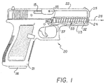
- a firearm 20 Typical of such a firearm is the Glock 17/17L/18/19/20/21 and 22 manufactured by Glock, GmbH of Austria and the Sigma 9 mm17/17L/18/22/24 manufactured by Smith & Wesson of Springfield, Massachusetts.
- the pistol 20 is a semi-automatic device.
- the pistol grip frame 21 holds a magazine 16 that contains a number of rounds of ammunition.
- the ammunition is spring biased in a direction toward a reciprocating firing chamber 22 (also referred to as a slide). Cartridges from spent rounds are ejected through ejection slot 15 when the reciprocating chamber 22 moves to the left or backward under recoil action following discharge.
- a barrel 25 extending from the reciprocating chamber 22 is connected to the pistol grip frame 21 via a modified take-down latch 36.
- a recoil chamber 23 Disposed beneath reciprocating chamber 22 is a recoil chamber 23.
- a laser sight 33 that replaces a conventional recoil spring guide rod.
- a recoil spring 32 which surrounds the laser sight 33, extends between an apertured projection 24 of the reciprocating chamber 22 at one end of the recoil chamber 23 and an annular seat 45 (FIG. 3) of the laser sight 33 at the other end of the recoil chamber 23.
- the laser sight 33 which includes a battery pack 34 that sits in one end of a casing 11 of the laser sight 33 and is enclosed therein by a removable end cap 35 with a ball tip electrical contact 41.
- the cap 35 is made of insulating material, preferably a soft polymer capable of absorbing the recoil shock of the reciprocating chamber 22.
- the cap 35 has internal recesses that receive lugs 12 of laser sight casing 11 for rotationally orienting the cap 35 with respect to the casing 11.
- the original take-down latch not shown, is replaced by the modified take-down latch 36 and a modified take-down latch spring 37.
- the spring 37 biases the latch 36 against a catch 19 (FIG. 5) of the barrel 25.
- the take-down latch 36 is generally made of a conducting metal but has a central insulating portion 46. In its normal centered position, the take-down latch 36 has its insulating portion 46 bearing against the ball tip electrical contact 41 of the cap 35 thereby interrupting the power to the laser sight 33 and maintaining the laser in an off condition.
- a lens housing 10 is press fit or otherwise suitably mounted on the casing 11. At one end there is a window 17. Set screws 9 adjust and align collimating lens assembly 8 contained in lens housing 10.
- a laser 27 such as a laser diode.
- Driver board 38 Connected to the laser 27 is a driver board 38 that provides both electrical power and control to flash the laser 27.
- Driver board 38 includes suitable electronic circuitry, including an oscillator for operating the laser 27 at a predetermined frequency and for a predetermined duty cycle.
- the circuitry is preferably of complementary metal oxide (CMOS) design that has relatively low power consumption and a controllable duty cycle.
- CMOS complementary metal oxide
- Driver board 38 is connected via a wire spring 39 to the battery pack 34.
- the battery pack 34 is in turn connected to the ball tip 41 in the end cap 35 via another wire spring 40.
- the projection 24 of the reciprocating chamber 22 forms a partial closure at one end of the recoil chamber 23.
- the recoil spring 32 is compressed between the projection 24 and the annular stop 45 of the end cap 35.
- a bore 14 through the projection 24 journals the lens housing 10 with a slide fit that accommodates the reciprocating action of the projection 24.
- the bore 14 also forms an aperture through which a beam 28 of laser light is emitted from the recoil chamber 23.
- a key portion 42 on the end cap 35 fits into the slot 26 to rotationally align the laser 33 within the recoil chamber 23.
- the set screws 9 are used to preadjust the beam 28 into a desired alignment with the barrel 25. Thereafter, the laser sight 33 can be reinserted into the recoil chamber 22 without adversely affecting the alignment or orientation of the beam 28.
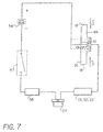
- the laser diode 27 has one end connected electrically and mechanically to the take-down latch 36 through the housing of laser sight 33, the recoil spring 32, and the recoil chamber 23.
- the other end of laser diode 27 is connected to the driver board 38, optional switch 47, the battery pack 34, and the ball tip contact 41.
- the driver board 38 has suitable electronic circuitry for flashing the laser 27 at a predetermined rate.
- the laser is flashed to prolong the life of the battery pack 34.
- the battery pack 34 preferably contains silver oxide or lithium batteries. Such batteries tend to refresh themselves between uses.
- the flashing of the laser diode 27 is also chosen to be at a frequency and duty cycle compatible with the refresh characteristic of the battery pack 34.
- the laser diode 27 is flashed at a frequency that is especially recognizable to the human eye. Such frequency is between 8 and 12 Hz and is preferably at approximately 10 Hz.
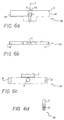
- the modified take-down latch 36 coupled to catch 19 of the barrel 25.
- the take-down latch may be moved in the direction of arrow B against the bias of spring 37.
- the take-down latch 36 is made from a steel blank. It is symmetrical about center line 7. Ridges 18 on both ends assist the user in manipulating the latch 36 horizontally and vertically. Insulating material 46 is disposed in the center of the latch 36 on face 6 that faces the ball tip contact 41. A rounded detent 5, which bears against the spring 37, keeps the latch 36 in position until the latch is manipulated by a user. Insulating material 46 fills a slot 4 and bore 3 that are machined into the metal latch 36.
- the material 46 is any suitable insulating material, preferably a moldable epoxy. Another slot 2 is machined to receive the catch 19 of the barrel 25.
- Other lasers may be adapted to the laser sight including a surface emitting laser that may not require a collimating lens. It is also within the skill of those in the art to apply the various advances to other firearms, including those having take-down latches of different configurations.
- the take-down latch of a pistol made by Beretta or SIG would have a general cylindrical shape and be adapted to have ball detents on each end to hold the latch in its left or right position. See FIGS. 8 and 9 for examples of take-down latches compatible with such firearms.
- a take-down latch 50 is provided for a Sig Sauer pistol (not shown).
- the latch 50 has detents 51, 52 disposed on opposite ends.
- a center insulative portion 53 electrically uncouples the battery pack 34.
- External flanges 54, 55 are manipulated by the user's trigger finger to turn on the laser sight 33.
- a similar latch 60 for a Beretta pistol is shown in FIG. 9.
- ball type detents 61, 62 hold the latch 60 in place.
- Center portion 63 is made of insulating material and external flanges 64, 65 are used to move the latch 60 off center and turn on the laser 27.
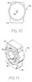
- FIGS. 10 and 11 show an alternative end cap 70 for the Sig Sauer pistol.
- the end cap 70 has similar internal recesses 72 for receiving lugs 12 of laser sight casing 11 and an opening 74 for the ball tip electrical contact 41.
- the cap is made with two differently shaped and positioned keys 76 and 78 that are designed to mate with preexisting features of the recoil chamber (not shown) of the SIG Sauer pistol.
- the cap 70 together with its keys 76 and 78 enables the laser sight to be preadjusted into a desired alignment with the firearm barrel and to be reinserted into the recoil chamber while preserving the alignment or orientation of the laser beam 28.
Landscapes
- Physics & Mathematics (AREA)
- Optics & Photonics (AREA)
- Engineering & Computer Science (AREA)
- General Engineering & Computer Science (AREA)
- Aiming, Guidance, Guns With A Light Source, Armor, Camouflage, And Targets (AREA)
- Laser Surgery Devices (AREA)
- Lasers (AREA)
- Semiconductor Lasers (AREA)
- Radiation-Therapy Devices (AREA)
Claims (17)
- Feuerwaffe (20), umfassend:das längliche Gehäuse einen Laser (27) und eine Batterie (34) zur Stromversorgung des Lasers enthält.einen Rahmen (21), der einen sich hin- und herbewegenden Schuss-Schlitten (22), einen Lauf (25) und eine Rückholkammer (23) mit einem länglichen Hohlraum trägt;ein Laservisier (33), das von einer Rückholfeder (32) innerhalb des Hohlraums umgeben ist;wobei das Laservisier (33) ein längliches Gehäuse und eine abnehmbare Endkappe (35) aufweist; und
- Feuerwaffe nach Anspruch 1, bei der die Endkappe (35) aus einem elektrisch isolierenden Material besteht.
- Feuerwaffe nach Anspruch 2, bei der das längliche Gehäuse auch einen elektrischen Kontakt enthält, der sich durch die Endkappe (35) hindurch erstreckt, um einen elektrischen Schaltkreis zwischen dem Laser und der Batterie zu schließen.
- Feuerwaffe nach Anspruch 1, bei der ein Fensterende des Laservisiers (33) durch einen Vorsprung des sich hin- und herbewegenden Schlittens (22) hindurchgleiten kann und sich die Rückholfeder (32) zwischen dem Vorsprung des sich hin- und herbewegenden Schlittens (22) und der Endkappe (35) erstreckt.
- Feuerwaffe nach Anspruch 4, bei der die Endkappe (35) einen ringförmigen Anschlag zum Eingreifen in die Rückholfeder (32) umfasst.
- Feuerwaffe nach Anspruch 1, bei der die Endkappe (35) beim Austausch wieder in eine vorbestimmte Ausrichtung in Bezug auf das längliche Gehäuse bringbar ist.
- Feuerwaffe nach Anspruch 1, bei der die Endkappe (35) so geformt ist, dass sie das Laservisier (33) gegen Drehung arretiert, um das Laservisier in Bezug auf den Lauf (25) auszurichten.
- Feuerwaffe nach Anspruch 7, bei der die zweite und die dritte Richtung in Bezug aufeinander entgegengesetzt sind.
- Feuerwaffe nach Anspruch 7, bei der der elektrische Schaltkreis eine Batterie und eine Treiberschaltung umfasst, die das Laservisier in einem Betriebszyklus aufblitzen lässt, der die Lebenslauer der Batterie verlängert.
- Feuerwaffe (20), umfassend:das zweite Ende des Laservisiers so geformt ist, dass das Laservisier gegen Drehung arretiert wird, um das Laservisier in Bezug auf den Lauf auszurichten.einen Rahmen (21), der einen sich hin- und herbewegenden Schuss-Schlitten (22), einen Lauf (25) und eine Rückholkammer (23) mit einem länglichen Hohlraum trägt;ein Laservisier (33), das von einer Rückholfeder (32) innerhalb des Hohlraums umgeben ist;wobei ein erstes Ende des Laservisiers (33) durch einen Vorsprung des sich hin- und herbewegenden Schlittens (22) hindurchgleiten kann und ein zweites Ende des Laservisiers durch passende Ausbildungen der Rückholkammer (23) gehalten wird; und
- Feuerwaffe nach Anspruch 10, bei der das Laservisier ein längliches Gehäuse und eine Endkappe (35) umfasst, die das zweite Ende des Laservisiers bildet.
- Feuerwaffe nach Anspruch 11, bei der sich die Rückholfeder (32) zwischen dem Vorsprung des sich hin- und herbewegenden Schlittens (22) und der Endkappe (35) erstreckt.
- Feuerwaffe nach Anspruch 12, bei der die Endkappe (35) einen ringförmigen Anschlag zum Eingreifen in die Rückholfeder (32) umfasst.
- Feuerwaffe nach Anspruch 11, bei der die Endkappe (35) in einer vorbestimmten Ausrichtung in Bezug auf das längliche Gehäuse abnehmbar und wieder einsetzbar ist.
- Feuerwaffe nach Anspruch 14, bei der die Endkappe (35) aus einem elektrisch isolierenden Material besteht.
- Feuerwaffe nach Anspruch 15, bei der das längliche Gehäuse einen Laser (27) und eine Batterie (34) zur Stromversorgung des Lasers enthält.
- Feuerwaffe nach Anspruch 16, bei der das längliche Gehäuse auch einen elektrischen Kontakt enthält, der sich durch die Endkappe erstreckt, um einen elektrischen Schaltkreis zwischen dem Laser (27) und der Batterie (34) zu schließen.
Applications Claiming Priority (3)
| Application Number | Priority Date | Filing Date | Title |
|---|---|---|---|
| US08/148,846 US5509226A (en) | 1993-11-08 | 1993-11-08 | Firearm with modified take down latch for controlling laser sight |
| EP95905842A EP0728292B1 (de) | 1993-11-08 | 1994-11-07 | Selbstausrichtendes laservisier |
| US148846 | 2005-06-09 |
Related Parent Applications (1)
| Application Number | Title | Priority Date | Filing Date |
|---|---|---|---|
| EP95905842A Division EP0728292B1 (de) | 1993-11-08 | 1994-11-07 | Selbstausrichtendes laservisier |
Publications (2)
| Publication Number | Publication Date |
|---|---|
| EP0997699A1 EP0997699A1 (de) | 2000-05-03 |
| EP0997699B1 true EP0997699B1 (de) | 2002-02-13 |
Family
ID=22527678
Family Applications (2)
| Application Number | Title | Priority Date | Filing Date |
|---|---|---|---|
| EP00100985A Expired - Lifetime EP0997699B1 (de) | 1993-11-08 | 1994-11-07 | Selbstausrichtendes Laservisier |
| EP95905842A Expired - Lifetime EP0728292B1 (de) | 1993-11-08 | 1994-11-07 | Selbstausrichtendes laservisier |
Family Applications After (1)
| Application Number | Title | Priority Date | Filing Date |
|---|---|---|---|
| EP95905842A Expired - Lifetime EP0728292B1 (de) | 1993-11-08 | 1994-11-07 | Selbstausrichtendes laservisier |
Country Status (5)
| Country | Link |
|---|---|
| US (1) | US5509226A (de) |
| EP (2) | EP0997699B1 (de) |
| AT (2) | ATE203818T1 (de) |
| DE (2) | DE69427866T2 (de) |
| WO (1) | WO1995013515A1 (de) |
Families Citing this family (48)
| Publication number | Priority date | Publication date | Assignee | Title |
|---|---|---|---|---|
| US5892221A (en) * | 1997-03-24 | 1999-04-06 | Lev; Shlomo | Combat simulation method and system utilizing lasers with wireless activation |
| US5901452A (en) * | 1997-08-29 | 1999-05-11 | Remington Arms Co., Inc. | Gunsight |
| US6366349B1 (en) | 1998-05-18 | 2002-04-02 | Lasermax, Inc. | Apparatus for aligning optical elements in response to the display of a reflected reticle image and method of aligning |
| US6025908A (en) * | 1998-05-18 | 2000-02-15 | Houde-Walter; William R. | Alignment of optical elements in telescopes using a laser beam with a holographic projection reticle |
| US6230431B1 (en) * | 1999-07-07 | 2001-05-15 | Limate Corporation | Night laser sight |
| US6591536B2 (en) | 2001-06-07 | 2003-07-15 | Lasermax Inc. | Method and apparatus for side of frame positioning of laser sights and LED illuminators |
| US7069685B2 (en) * | 2003-09-12 | 2006-07-04 | Lasermax, Inc. | Diffractive head up display for firearms |
| US20050180486A1 (en) * | 2004-02-13 | 2005-08-18 | Tung Hsin C. | Laser module for circular saw |
| US20050252061A1 (en) * | 2004-05-14 | 2005-11-17 | Sloan Robert W | Guide rod with integrated illumination device |
| US20060026886A1 (en) * | 2004-07-15 | 2006-02-09 | Doukas Antonios E | Rapid activation system for a laser-sighting assembly |
| US20070074442A1 (en) * | 2005-10-05 | 2007-04-05 | Richeson Leland J | Gunstock having laser sighting device |
| US8695266B2 (en) * | 2005-12-22 | 2014-04-15 | Larry Moore | Reference beam generating apparatus |
| US7421818B2 (en) * | 2006-02-04 | 2008-09-09 | Lasermax, Inc. | Firearm mount with embedded laser sight |
| US8695267B2 (en) * | 2006-02-04 | 2014-04-15 | Lasermax, Inc. | Firearm mount with embedded sight |
| WO2007091262A1 (en) | 2006-02-09 | 2007-08-16 | Dov Pikielny | Firearm with on-off safety switch |
| US7726059B2 (en) * | 2007-03-07 | 2010-06-01 | Dov Pikielny | Lockable safety for firearm |
| US8028461B2 (en) * | 2007-06-18 | 2011-10-04 | Patricia NuDyke | Switch for the control of weapon mounted electronic assemblies, a weapon having a control switch and a method for using weapon |
| US8312665B2 (en) | 2008-10-10 | 2012-11-20 | P&L Industries, Inc. | Side-mounted lighting device |
| US20100154279A1 (en) * | 2008-12-23 | 2010-06-24 | Para Usa, Inc. | Firearm |
| US8683727B2 (en) | 2010-11-22 | 2014-04-01 | DM Innovations | Firearm accessory part with tracking capability |
| US9170079B2 (en) | 2011-01-18 | 2015-10-27 | Larry E. Moore | Laser trainer cartridge |
| US8826582B2 (en) * | 2011-11-26 | 2014-09-09 | Orval E. Bowman | Pointing devices, apparatus, systems and methods for high shock environments |
| US9638493B2 (en) | 2011-11-26 | 2017-05-02 | Orval E. Bowman | Pointing devices, apparatus, systems and methods for high shock environments |
| US10532275B2 (en) | 2012-01-18 | 2020-01-14 | Crimson Trace Corporation | Laser activated moving target |
| US9057579B2 (en) | 2012-05-11 | 2015-06-16 | Surefire, Llc | Quick draw gun holster |
| US8985412B2 (en) | 2012-05-11 | 2015-03-24 | Surefire, Llc | Quick draw gun holster |
| US9057580B2 (en) * | 2012-05-11 | 2015-06-16 | Surefire, Llc | Quick draw gun holster with interactive accessory device |
| US9423213B2 (en) * | 2012-11-14 | 2016-08-23 | Lasermax Inc | Recoil spring guide mounted target marker |
| US8844189B2 (en) | 2012-12-06 | 2014-09-30 | P&L Industries, Inc. | Sighting device replicating shotgun pattern spread |
| US9297614B2 (en) | 2013-08-13 | 2016-03-29 | Larry E. Moore | Master module light source, retainer and kits |
| US9182194B2 (en) | 2014-02-17 | 2015-11-10 | Larry E. Moore | Front-grip lighting device |
| US9644826B2 (en) | 2014-04-25 | 2017-05-09 | Larry E. Moore | Weapon with redirected lighting beam |
| US10436553B2 (en) | 2014-08-13 | 2019-10-08 | Crimson Trace Corporation | Master module light source and trainer |
| US10156423B2 (en) | 2015-01-09 | 2018-12-18 | Hogue, Inc. | Firearm handgrip assembly with laser gunsight system |
| US9903687B2 (en) * | 2015-01-20 | 2018-02-27 | Crosman Corporation | Compact spring guide rod laser |
| US10132595B2 (en) | 2015-03-20 | 2018-11-20 | Larry E. Moore | Cross-bow alignment sighter |
| US9851178B2 (en) | 2015-07-10 | 2017-12-26 | Frank T. Cosso | Laser sight with proximity sensor |
| USD777559S1 (en) * | 2015-12-08 | 2017-01-31 | Sukhwinder Dhaliwal | Semiautomatic pistol-shaped key |
| US9829280B1 (en) | 2016-05-26 | 2017-11-28 | Larry E. Moore | Laser activated moving target |
| US10209030B2 (en) | 2016-08-31 | 2019-02-19 | Larry E. Moore | Gun grip |
| US10866042B1 (en) * | 2016-11-30 | 2020-12-15 | Battlearms Ip, Llc | Takedown pin for a firearm |
| US10222171B2 (en) | 2016-12-01 | 2019-03-05 | Bushnell Inc. | Forward grip laser (FGL) |
| US10436538B2 (en) | 2017-05-19 | 2019-10-08 | Crimson Trace Corporation | Automatic pistol slide with laser |
| USD915541S1 (en) | 2017-10-06 | 2021-04-06 | Vista Outdoor Operations Llc | Forward grip laser sight |
| USD860375S1 (en) | 2017-10-06 | 2019-09-17 | Bushnell Inc. | Forward grip laser sight |
| US10209033B1 (en) | 2018-01-30 | 2019-02-19 | Larry E. Moore | Light sighting and training device |
| US11320244B2 (en) * | 2018-07-02 | 2022-05-03 | Alex Verjovsky | Rifle with laser and illuminator system integrated into rail |
| CA3228412A1 (en) | 2021-08-11 | 2023-02-16 | Matthew GELINEAU | Field installable laser alignment tool |
Family Cites Families (27)
| Publication number | Priority date | Publication date | Assignee | Title |
|---|---|---|---|---|
| US1452651A (en) * | 1921-10-15 | 1923-04-24 | Charles H Norrlin | Target finder for firearms |
| US3573868A (en) * | 1967-11-13 | 1971-04-06 | Carlo Giannetti | Fiber optical target practice system |
| US3513581A (en) * | 1968-06-04 | 1970-05-26 | Olin Slater | Flashlight attachment for guns |
| US4026054A (en) * | 1976-02-02 | 1977-05-31 | Snyder Wesley L | Laser aiming system for weapons |
| US4161076A (en) * | 1977-10-31 | 1979-07-17 | Snyder Wesley L | Aiming system for weapons |
| US4541689A (en) * | 1983-09-19 | 1985-09-17 | Optical Storage International | Friction wedge alignment system for laser diode collimator pens |
| CH654655A5 (en) * | 1983-12-02 | 1986-02-28 | Decobul S A | Laser site for a firearm |
| US4678288A (en) * | 1984-04-27 | 1987-07-07 | Spectra-Physics, Inc. | Trifocal lens for a laser instrument |
| US4627183A (en) * | 1985-04-11 | 1986-12-09 | Stuckman Lowell R | Firearm with aiming light |
| US4694182A (en) * | 1986-02-27 | 1987-09-15 | Spectra-Physics, Inc. | Hand held bar code reader with modulated laser diode and detector |
| US4731795A (en) * | 1986-06-26 | 1988-03-15 | Amoco Corporation | Solid state laser |
| US4777754A (en) * | 1986-12-12 | 1988-10-18 | Laser Products Corporation | Light beam assisted aiming of firearms |
| CH673898A5 (de) * | 1988-01-26 | 1990-04-12 | Peter Gerber | |
| US4910741A (en) * | 1988-06-06 | 1990-03-20 | Massachusetts Institute Of Technology | Laser diode source assembly |
| US4884275A (en) * | 1988-10-24 | 1989-11-28 | Murasa International | Laser safety shutoff system |
| US4916579A (en) * | 1989-01-26 | 1990-04-10 | Murasa International | Gradient index zoom illuminator |
| US4897850A (en) * | 1989-02-01 | 1990-01-30 | Amoco Corporation | Assembly for arranging optical components of a laser |
| US4934086A (en) * | 1989-03-31 | 1990-06-19 | Houde Walter William R | Recoil spring guide mounting for laser sight |
| DE3918357C1 (de) * | 1989-06-06 | 1990-11-29 | Thorsten 4424 Stadtlohn De Erning | |
| US5121188A (en) * | 1990-05-16 | 1992-06-09 | Applied Laser Systems | Laser module assembly |
| US5111476A (en) * | 1991-02-21 | 1992-05-05 | Applied Laser Systems | Method and apparatus for aligning a laser diode, and laser diode system produced thereby |
| US5179235A (en) * | 1991-09-10 | 1993-01-12 | Toole Ronald L | Pistol sighting device |
| US5237773A (en) * | 1991-09-20 | 1993-08-24 | Claridge Hi-Tec Inc. | Integral laser sight, switch for a gun |
| US5392550A (en) * | 1993-01-14 | 1995-02-28 | Moore; Larry | Internal laser sight for weapons |
| US5351429A (en) * | 1993-02-26 | 1994-10-04 | Ford Wilson H | Laser sighting device for firearms |
| US5355608A (en) * | 1993-06-08 | 1994-10-18 | Teetzel James W | Concealed laser module sight apparatus |
| US5388364A (en) * | 1993-06-14 | 1995-02-14 | Paldino; Arthur | Internally mounted laser gunsight |
-
1993
- 1993-11-08 US US08/148,846 patent/US5509226A/en not_active Expired - Lifetime
-
1994
- 1994-11-07 EP EP00100985A patent/EP0997699B1/de not_active Expired - Lifetime
- 1994-11-07 WO PCT/US1994/012811 patent/WO1995013515A1/en not_active Ceased
- 1994-11-07 DE DE69427866T patent/DE69427866T2/de not_active Expired - Fee Related
- 1994-11-07 AT AT95905842T patent/ATE203818T1/de not_active IP Right Cessation
- 1994-11-07 EP EP95905842A patent/EP0728292B1/de not_active Expired - Lifetime
- 1994-11-07 AT AT00100985T patent/ATE213319T1/de not_active IP Right Cessation
- 1994-11-07 DE DE69429885T patent/DE69429885T2/de not_active Expired - Fee Related
Also Published As
| Publication number | Publication date |
|---|---|
| EP0728292B1 (de) | 2001-08-01 |
| DE69429885T2 (de) | 2002-10-31 |
| EP0728292A4 (de) | 1997-09-24 |
| DE69427866D1 (de) | 2001-09-06 |
| ATE213319T1 (de) | 2002-02-15 |
| DE69427866T2 (de) | 2002-04-11 |
| WO1995013515A1 (en) | 1995-05-18 |
| ATE203818T1 (de) | 2001-08-15 |
| EP0997699A1 (de) | 2000-05-03 |
| US5509226A (en) | 1996-04-23 |
| DE69429885D1 (de) | 2002-03-21 |
| EP0728292A1 (de) | 1996-08-28 |
Similar Documents
| Publication | Publication Date | Title |
|---|---|---|
| EP0728292B1 (de) | Selbstausrichtendes laservisier | |
| US5355608A (en) | Concealed laser module sight apparatus | |
| US11994363B2 (en) | Firearm laser sight alignment assembly | |
| US5557872A (en) | Power supply for firearm accessories | |
| EP2161532B1 (de) | Feuerwaffe mit aufgesetzter Zielvorrichtung | |
| US5388364A (en) | Internally mounted laser gunsight | |
| US6622416B2 (en) | Target and navigation illuminators for firearms | |
| US10323903B2 (en) | Auto on gun accessory | |
| US5375362A (en) | Laser sighted firearm | |
| US5351429A (en) | Laser sighting device for firearms | |
| EP2470853B1 (de) | Übungsfeuerwaffe mit verstellbaren abzug | |
| EP2208960B1 (de) | Langloch-montierte Zielvorrichtung | |
| US4856218A (en) | Light beam assisted aiming of firearms | |
| US8006428B2 (en) | Gun-mounted sighting device | |
| US5481819A (en) | Laser module apparatus | |
| US5392550A (en) | Internal laser sight for weapons | |
| US6360469B1 (en) | Electronically fired revolver utilizing percussively actuated cartridges | |
| US6345461B1 (en) | Backstrap module for a firearm | |
| US20180172395A1 (en) | Firearm handgrip assembly with laser gunsight system | |
| US6345462B1 (en) | Firing mechanism for use in a firearm having an electronic firing probe for discharging non-impact fired ammunition | |
| RU2539019C1 (ru) | Пистолет с лазерным целеуказателем | |
| EP2192374A2 (de) | Feuerwaffe mit aufgesetzter Zielvorrichtung | |
| ITRM950084A1 (it) | Dispositivo di mira laser armi da fuoco manuali. |
Legal Events
| Date | Code | Title | Description |
|---|---|---|---|
| PUAI | Public reference made under article 153(3) epc to a published international application that has entered the european phase |
Free format text: ORIGINAL CODE: 0009012 |
|
| AC | Divisional application: reference to earlier application |
Ref document number: 728292 Country of ref document: EP |
|
| AK | Designated contracting states |
Kind code of ref document: A1 Designated state(s): AT CH DE FR GB IT LI |
|
| 17P | Request for examination filed |
Effective date: 20000614 |
|
| AKX | Designation fees paid |
Free format text: AT CH DE FR GB IT LI |
|
| GRAG | Despatch of communication of intention to grant |
Free format text: ORIGINAL CODE: EPIDOS AGRA |
|
| 17Q | First examination report despatched |
Effective date: 20010207 |
|
| GRAG | Despatch of communication of intention to grant |
Free format text: ORIGINAL CODE: EPIDOS AGRA |
|
| GRAH | Despatch of communication of intention to grant a patent |
Free format text: ORIGINAL CODE: EPIDOS IGRA |
|
| GRAH | Despatch of communication of intention to grant a patent |
Free format text: ORIGINAL CODE: EPIDOS IGRA |
|
| GRAA | (expected) grant |
Free format text: ORIGINAL CODE: 0009210 |
|
| REG | Reference to a national code |
Ref country code: GB Ref legal event code: IF02 |
|
| AC | Divisional application: reference to earlier application |
Ref document number: 728292 Country of ref document: EP |
|
| AK | Designated contracting states |
Kind code of ref document: B1 Designated state(s): AT CH DE FR GB IT LI |
|
| REF | Corresponds to: |
Ref document number: 213319 Country of ref document: AT Date of ref document: 20020215 Kind code of ref document: T |
|
| REG | Reference to a national code |
Ref country code: CH Ref legal event code: EP |
|
| REF | Corresponds to: |
Ref document number: 69429885 Country of ref document: DE Date of ref document: 20020321 |
|
| ET | Fr: translation filed | ||
| PLBE | No opposition filed within time limit |
Free format text: ORIGINAL CODE: 0009261 |
|
| STAA | Information on the status of an ep patent application or granted ep patent |
Free format text: STATUS: NO OPPOSITION FILED WITHIN TIME LIMIT |
|
| 26N | No opposition filed |
Effective date: 20021114 |
|
| PGFP | Annual fee paid to national office [announced via postgrant information from national office to epo] |
Ref country code: CH Payment date: 20081125 Year of fee payment: 15 |
|
| PGFP | Annual fee paid to national office [announced via postgrant information from national office to epo] |
Ref country code: AT Payment date: 20081021 Year of fee payment: 15 |
|
| PGFP | Annual fee paid to national office [announced via postgrant information from national office to epo] |
Ref country code: IT Payment date: 20081127 Year of fee payment: 15 |
|
| PGFP | Annual fee paid to national office [announced via postgrant information from national office to epo] |
Ref country code: FR Payment date: 20081117 Year of fee payment: 15 |
|
| PGFP | Annual fee paid to national office [announced via postgrant information from national office to epo] |
Ref country code: DE Payment date: 20081223 Year of fee payment: 15 |
|
| PGFP | Annual fee paid to national office [announced via postgrant information from national office to epo] |
Ref country code: GB Payment date: 20081128 Year of fee payment: 15 |
|
| REG | Reference to a national code |
Ref country code: CH Ref legal event code: PL |
|
| GBPC | Gb: european patent ceased through non-payment of renewal fee |
Effective date: 20091107 |
|
| REG | Reference to a national code |
Ref country code: FR Ref legal event code: ST Effective date: 20100730 |
|
| PG25 | Lapsed in a contracting state [announced via postgrant information from national office to epo] |
Ref country code: AT Free format text: LAPSE BECAUSE OF NON-PAYMENT OF DUE FEES Effective date: 20091107 |
|
| PG25 | Lapsed in a contracting state [announced via postgrant information from national office to epo] |
Ref country code: CH Free format text: LAPSE BECAUSE OF NON-PAYMENT OF DUE FEES Effective date: 20091130 Ref country code: FR Free format text: LAPSE BECAUSE OF NON-PAYMENT OF DUE FEES Effective date: 20091130 Ref country code: LI Free format text: LAPSE BECAUSE OF NON-PAYMENT OF DUE FEES Effective date: 20091130 |
|
| PG25 | Lapsed in a contracting state [announced via postgrant information from national office to epo] |
Ref country code: DE Free format text: LAPSE BECAUSE OF NON-PAYMENT OF DUE FEES Effective date: 20100601 |
|
| PG25 | Lapsed in a contracting state [announced via postgrant information from national office to epo] |
Ref country code: GB Free format text: LAPSE BECAUSE OF NON-PAYMENT OF DUE FEES Effective date: 20091107 |
|
| PG25 | Lapsed in a contracting state [announced via postgrant information from national office to epo] |
Ref country code: IT Free format text: LAPSE BECAUSE OF NON-PAYMENT OF DUE FEES Effective date: 20091107 |