EP0997750A2 - Retroreflektierende Folie mit einem Bild zur Echtheitsprüfung und Verfahren zur ihrer Herstellung - Google Patents
Retroreflektierende Folie mit einem Bild zur Echtheitsprüfung und Verfahren zur ihrer Herstellung Download PDFInfo
- Publication number
- EP0997750A2 EP0997750A2 EP99308606A EP99308606A EP0997750A2 EP 0997750 A2 EP0997750 A2 EP 0997750A2 EP 99308606 A EP99308606 A EP 99308606A EP 99308606 A EP99308606 A EP 99308606A EP 0997750 A2 EP0997750 A2 EP 0997750A2
- Authority
- EP
- European Patent Office
- Prior art keywords
- layer
- image
- transparent
- lenses
- retroreflective sheet
- Prior art date
- Legal status (The legal status is an assumption and is not a legal conclusion. Google has not performed a legal analysis and makes no representation as to the accuracy of the status listed.)
- Granted
Links
Images



Classifications
-
- G—PHYSICS
- G02—OPTICS
- G02B—OPTICAL ELEMENTS, SYSTEMS OR APPARATUS
- G02B5/00—Optical elements other than lenses
- G02B5/12—Reflex reflectors
- G02B5/126—Reflex reflectors including curved refracting surface
- G02B5/128—Reflex reflectors including curved refracting surface transparent spheres being embedded in matrix
-
- Y—GENERAL TAGGING OF NEW TECHNOLOGICAL DEVELOPMENTS; GENERAL TAGGING OF CROSS-SECTIONAL TECHNOLOGIES SPANNING OVER SEVERAL SECTIONS OF THE IPC; TECHNICAL SUBJECTS COVERED BY FORMER USPC CROSS-REFERENCE ART COLLECTIONS [XRACs] AND DIGESTS
- Y10—TECHNICAL SUBJECTS COVERED BY FORMER USPC
- Y10S—TECHNICAL SUBJECTS COVERED BY FORMER USPC CROSS-REFERENCE ART COLLECTIONS [XRACs] AND DIGESTS
- Y10S359/00—Optical: systems and elements
- Y10S359/90—Methods
-
- Y—GENERAL TAGGING OF NEW TECHNOLOGICAL DEVELOPMENTS; GENERAL TAGGING OF CROSS-SECTIONAL TECHNOLOGIES SPANNING OVER SEVERAL SECTIONS OF THE IPC; TECHNICAL SUBJECTS COVERED BY FORMER USPC CROSS-REFERENCE ART COLLECTIONS [XRACs] AND DIGESTS
- Y10—TECHNICAL SUBJECTS COVERED BY FORMER USPC
- Y10T—TECHNICAL SUBJECTS COVERED BY FORMER US CLASSIFICATION
- Y10T428/00—Stock material or miscellaneous articles
- Y10T428/25—Web or sheet containing structurally defined element or component and including a second component containing structurally defined particles
-
- Y—GENERAL TAGGING OF NEW TECHNOLOGICAL DEVELOPMENTS; GENERAL TAGGING OF CROSS-SECTIONAL TECHNOLOGIES SPANNING OVER SEVERAL SECTIONS OF THE IPC; TECHNICAL SUBJECTS COVERED BY FORMER USPC CROSS-REFERENCE ART COLLECTIONS [XRACs] AND DIGESTS
- Y10—TECHNICAL SUBJECTS COVERED BY FORMER USPC
- Y10T—TECHNICAL SUBJECTS COVERED BY FORMER US CLASSIFICATION
- Y10T428/00—Stock material or miscellaneous articles
- Y10T428/31504—Composite [nonstructural laminate]
- Y10T428/31551—Of polyamidoester [polyurethane, polyisocyanate, polycarbamate, etc.]
- Y10T428/31634—Next to cellulosic
- Y10T428/31638—Cellulosic ester
Definitions
- the present invention relates to a retroreflective sheeting with an image, more specifically a validation image.
- a watermark is an identifying pattern or legend either on or in a material to provide validation of the material. Retroreflective sheeting with directional and non-directional watermarks have been used as a validation means for documents, phonographs, cassette tapes, compact disk containers, traffic signage and license plates.
- This invention relates to retroreflective sheeting which has an image, such as a validation image.
- the image is directional having varying appearance at different angles of view.
- the retroreflective sheeting has a layer of transparent microsphere lenses, a transparent polymeric spacing layer underlying, contacting, and conforming to the bottom of the lenses, the spacing and conformation of which is critical to the optimal performance of the retroreflective article, a reflective layer having a top surface in contact with the back surface of the spacing layer and a topcoat and/or cover sheet overlying and conforming to the top surfaces of the lenses and having a flat top surface or face.
- the retroreflective sheeting includes a pressure sensitive or thermally activated adhesive underlying and in contact with the reflective layer.
- the retroreflective sheeting has an image whose proportions are determined by a non-conformity of the reflective and spacing layer to the bottom of the lenses.
- the image of the present invention can range from conspicuous to inconspicuous and directional to non-directional.
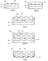
- Fig. 1 is a cross sectional view of a retroreflective sheeting.
- Fig. 2 is a cross sectional view of a retroreflective sheeting.
- Fig. 3 is a cross sectional view of a retroreflective sheeting.
- Fig. 4 is an illustration of the method of imparting the image.
- Fig. 5 is an illustration of an alternative method of imparting the image.
- Fig. 6 is an illustration of an another alternative method of imparting the image.
- the invention relates to a retroreflective sheeting which has an image.
- the image is a portion of the reflective layer which does not conform; or is less conforming to the back surface of the microsphere lenses.
- the portion of the reflective layer, which is out of conformity, does not provide the same magnitude of retroreflectivity as the conforming areas.
- This non-conforming area can range from a "dead" or nonreflecting, to a less reflecting portion, to a greater reflecting portion of the retroreflective sheeting. This difference in reflective characteristic leads to the image's viewability.
- the apparent intensity of the image is related to the degree of non-conformity of the spacing and/or the reflective layers.
- the retroreflective sheeting has a layer of transparent microsphere lenses.
- the microsphere lenses may have any refractive index or average diameter provided that the beads provide the necessary refraction for the retroreflective application.
- the microsphere lenses are characterized as having an average refractive index in the range of about 1.8 to about 2.5, or from about 1.9 to about 2.4, or from about 2.1 to about 2.3 and an average diameter of about 35 to about 100, or from about 45 to about 90, or from about 55 to about 80 microns.
- the range and ratio limits may be combined.
- the transparent microsphere lenses utilized in the retroreflective sheeting of the present invention may be characterized as having average diameters in a range of from about 25 to about 300, 30 to about 120 microns, and more often in a range from about 40 to about 80 microns.
- the index of refraction of the microsphere lenses is generally in the range from about 1.9 to about 2.5, more typically is in the range from about 2.0 to about 2.3, and most often between about 2.10 to about 2.2.
- Glass microspheres are typically used although ceramic microspheres such as those made by sol/gel techniques can also be used.
- the index of refraction and the average diameter of the microspheres, and the index of refraction of the topcoat and/or cover sheet and space coat dictate the thickness of the spacing film.
- the microspheres can be subjected to chemical or physical treatments to improve the bond of the microspheres to the polymeric films.
- the microspheres can be treated with a fluorocarbon or an adhesion promoting agent such as an aminosilane to improve the bond, or the space coat layer in which the lenses have been embedded can be subjected to a flame treatment or corona discharge to improve the bond between the space coat and lenses to the subsequently applied topcoat and or cover sheet.
- the retroreflective sheeting also has a spacing layer generally conforming to the bottom surface of the microsphere lenses.
- the thickness of the polymeric spacing layer or space coat is from about 25% to about 100%, or from 40% to about 60% of the average diameter of the microsphere lenses.
- Various thermoplastic polymeric resins have been used previously in forming the spacing layer of embedded lens retroreflective sheeting, and such resins can be used in the sheeting of the present invention.
- the resins that may be used for the spacing layer include a variety of partially amorphous or semi-crystalline thermoplastic polymers which generally have a soft stage during which the lenses can be embedded in the films.
- the material used to form the spacing film or layer should be compatible with the topcoat material and adapted to form a good bond with the topcoat (and the microsphere lenses).
- the adhesion between the materials is greater than the tensile strength of the materials.
- Acrylics, polyvinyl butyrals, aliphatic urethanes and polyesters are particularly useful polymer materials because of their outdoor stability.
- Copolymers of ethylene and an acrylic acid or methacrylic acid; vinyls, fluoropolymers, polyethylenes, cellulose acetate butyrate, polycarbonates and polyacrylates are other examples of polymers that can be used for the topcoat and spacing layers of the sheeting of the invention.
- elastomeric properties to provide retroreflective sheeting which may be repeatedly stretched or flexed, and upon release of the stretching or flexing tension, rapidly return to substantially their original dimensions without significant loss of retroreflectivity.
- Polyurethanes are available which possess such elastomeric properties and these materials can be used as space coat materials.
- a topcoat / cover sheet layer may consist of any of the aforementioned materials in combination with a transparent pressure sensitive adhesive (such as AS352RX acrylic adhesive from Avery Chemical in Mill Hall Pennsylvania) underlying the cover sheet and in intimate contact and conforming to the microspheres.
- a transparent pressure sensitive adhesive such as AS352RX acrylic adhesive from Avery Chemical in Mill Hall Pennsylvania
- the cover sheet or pressure sensitive adhesive can be colored with a transparent pigment or dye or even be printed with a graphic which can be located on the interior or the exterior of the cover sheet.
- the pressure sensitive adhesive can be replaced by a thermal bonding layer, a heat activated adhesive, or a material which forms chemical bonds to the cover sheet.
- the retroreflective sheeting has a topcoat or cover sheet overlying and conforming to the top surface of the microsphere lenses.
- the coating weight of the topcoat may range from about 25 to 175 gms/m 2 .
- the coating weight is about 50 to 150 gms/m 2 and more preferably is from about 60 to 120 gms/m 2 .
- the topcoat thickness may range from 25 to about 125 microns and more often is from about 50-100 microns.
- the cover may comprise various thermoplastic polymers including acrylic polymer such as polymethylmethacrylate, vinyl polymers such as PVC and vinyl acrylic copolymers, or polyurethanes such as aliphatic polyether urethanes.
- Cover sheets include an impact modified polymethylmethacrylate (PMMA) (e.g., PlexiglasTM acrylic DR, MI-7 (Rohm & Haas), PerspexTM acrylic HI-7 (ICI), or blends thereof), a vinyl acrylic formulation (methyl methacrylate/ butyl methacrylate) copolymer and a PVC homopolymer) or a polyurethane.
- PMMA polymethylmethacrylate
- MI-7 Rohm & Haas
- ICI PerspexTM acrylic HI-7
- the aliphatic polyurethane cover sheet is produced by casting the urethane onto a polymer coated paper casting sheet or onto a polymer casting sheet.
- Casting sheet products are well known to the industry and supplied by companies such as Felix Schoeller Technical Papers, Pulaski, N.Y., S.D. Warren of Newton Center, Massachusetts and Ivex Corporation of Troy, Ohio.
- the urethane coating is coated onto the casting sheet by standard coating methods such as curtain coating, slot die coating, reverse roll coating, knife over roll coating, air knife coating, gravure coating, reverse gravure coating, offset gravure coating, Meyer rod coating, etc.
- technical expertise is applied to determine the optimal urethane solution viscosity.
- the retroreflective sheeting may also include a pressure sensitive adhesive and optionally a release liner.
- a pressure sensitive adhesive can be applied over the reflective layer to protect the reflective layer and to serve a functional purpose such as adhering the sheeting to a substrate.
- Conventional pressure-sensitive adhesives such as acrylic-based adhesives, or heat- or solvent-activated adhesives are typically used and may be applied by conventional procedures.
- a preformed layer of adhesive on a carrier web or release liner can be laminated to the reflective layer.
- Conventional release liners can be utilized in the formation of the retroreflective sheeting of the present invention.
- retroreflective sheeting 10 has a cover sheet, e.g. a polyurethane 11, in which are embedded glass microspheres 12.
- the glass microspheres are also adhered to spacecoat, e.g. polyvinylbutyral, 13.
- Spacecoat e.g. polyvinylbutyral
- Reflecting surface (vapor deposited aluminum) 14 is attached to spacecoat 13.
- a pressure sensitive adhesive 15 and release liner 16 are adhered to reflecting surface 14.
- Images 17 and 18 are portions of the reflective and spacecoat layers which are non-conforming to the glass beads 12.
- Fig. 2 illustrates a retroreflective sheeting which does not have a pressure sensitive adhesive.
- Retroreflective sheeting 20 has cover sheet 21 attached to glass microspheres 22, which are also attached to spacecoat 23.
- a reflecting surface 24 is on spacecoat 23.
- Images 25 and 26 are non-conforming sections of the reflective and spacecoat layers 23 and 24.
- Fig. 3 illustrates a retroreflective sheeting which has a multilayer covering.
- Retroreflective sheet 30 which has cover sheet 31 which is adhered to pressure sensitive adhesive 32.
- Adhesive 32 is bonded to glass microspheres 33, which are also attached to spacecoat 34.
- a reflecting surface 35 is on spacecoat 34.
- the reflecting surface 35 is adhered to pressure sensitive adhesive 36 which is also releasably adhered to release liner 37.
- the retroreflective sheeting has images 38 and 39.
- the images of the present invention may be prepared by using embossing or flexographic printing techniques.
- the images may be prepared by pressing a pattern into the retroreflective sheeting at the pressure and temperature necessary to provide the desired image.
- the retroreflective sheeting can be made by procedures normally used in the industry.
- the sheeting of the invention can be prepared by first extruding or casting a space coat layer of desired thickness on a polymer coated casting sheet and drying if necessary.
- the space coat layer is reheated to provide a tacky surface upon which microspheres are cascade-coated to form a monolayer of the microspheres.
- heat and/or pressure can be applied at this stage to facilitate microsphere embedding.
- the microspheres generally are embedded into the layer to a depth of about one-half of the average diameter of the microspheres. It is important that the space coat adapts a contour parallel to the microsphere surface.
- the topcoat is then applied over the top of the exposed and partially embedded microspheres.
- topcoating is applied by standard coating methods such as those described above. It is also possible to cast the topcoat as a separate, single layer film using these coating techniques. To achieve proper performance and coat weight thickness in each of the coating operations, technical expertise must be applied to determine the optimal solution viscosity. The application of these coating techniques is well known and is described above. Extrusion or extrusion coating are alternate methods of forming a topcoat. If required, the topcoat and the base coat layer are then subjected to an elevated temperature to dry or cure.
- the polymer coated casting sheet then is stripped from the space coat layer, and a reflective layer is subsequently applied over the back surface of the space coat.
- a reflective layer of silver or aluminum metal can be applied by vapor deposition over the back surface of the space coat.
- the thickness of the reflective layer depends on the particular metal used and is generally between about 500 and 1000 nanometers.
- the topcoat layer then can be printed (e.g. with UV radiation curable inks) to provide monocolor or multicolor images with the optional transparent overcoat.
- An alternate manufacturing process for enclosed bead-type retroreflective products can be used by first applying a polyurethane mixture onto a casting sheet and exposing the newly cast film to heat for solvent evaporation and urethane curing. After the film is formed, a bead bonding layer is applied and typically exposed to elevated temperatures for curing and/or evaporation of a carrier vehicle, such as solvent. Though many materials may be used for the bead bond layer, a thermoplastic polymer is preferred. The bead bond layer can then be partially cured or re-softened by the application of heat to allow cascade coated microspheres to form a monolayer of microspheres.
- the microspheres generally are embedded into the bead bond layer in a process that uses the application of heat and/or pressure.
- the space coat layer of desired thickness is then applied over the exposed microspheres.
- the space coat and base coat layers are subjected to elevated temperatures to complete solvent drying and / or curing and to provide adequate conformation of the spacecoat to the microsphere surface.
- a reflective layer is subsequently applied over the back surface of the space coat layer.
- the top aliphatic polyurethane layer can be printed (e.g. with UV radiation curable inks) to provide monocolor or multicolor images with the optional transparent overcoat or overlaminate film.
- the retroreflective sheeting described in a previous paragraph is provided with a pressure-sensitive adhesive construction.
- a pressure-sensitive adhesive is coated onto a release coated liner (paper or polymer) thereafter the adhesive coated liner is pressure laminated to the exposed surface of the reflective layer.
- Fig. 1 This embodiment is illustrated in Fig. 1.
- the release coated liner can subsequently be removed and the retroreflective sheeting can be adhesively applied to other surfaces.
- the validation image has at least one portion which is non-conforming to the lenses.
- the image is prepared by pressing the image design into the reflective surface of the retroreflective sheeting.
- the reflective layer of retroreflective sheeting is forced against a heated roll, such as a heated steel roll, by another roll, such as a rubber embossing or a flexo printing roll, containing the design of the image.
- the pressure and temperature as well as the speed of the roll affect the flattening of the crowns of the reflective layer.
- the pressure is typically from about 5 to about 75, or from about 10 to about 35, or from about 15 to about 25 pounds per linear inch (pli).
- the temperature of the heated roll is from about 85 to about 130, or from about 90 to about 120, or from about 95 to about 110 degrees C.
- the speed of the roll is typically from about 5 to about 100, or from about 8 to about 80, or from about 10 to about 60 ft/min.
- the mechanical stops on the embossing and flexographic printing equipment are set to control the depth of the impression of the image. The mechanical stops are set so that the roll with the image design is not forced onto the heated roll when between the raised image designs. The roll with the image design then just touches or kisses the surface of the retroreflective sheeting, thus forming the image.
- Fig. 4 illustrates the method of imparting the image.
- Heated steel roll 41 contacts the reflective side of retroreflective sheeting 42.
- the topcoat side of sheeting 42 is pressed against flexographic roll 43 bearing the raised impression 44 of the desired image. After being subjected to the heating and pressing step, the sheeting 42 has images.
- the roll used for the image design may be any roll used for embossing or flexo printing.
- the advantage of the present process is that the relatively inexpensive equipment may be used for preparing the retroreflective sheeting with the image. With the use of the heated roll the present process provides a simple means to prepare a retroreflective sheeting with an image.
- An alternative method of imparting an image can be made by first embossing an image into the face of the polymer coated surface of a casting sheet. This can easily be done into thermoplastic materials using the techniques for embossing holographic images.
- the sheeting of the invention can be prepared by first extruding or casting a space coat layer of desired thickness on an imaged polymer coated casting sheet and drying if necessary.
- the space coat layer is reheated to provide a tacky surface upon which microspheres are cascade-coated to form a monolayer of the microspheres.
- heat and/or pressure can be applied at this stage to facilitate microsphere embedding.
- the microspheres generally are embedded into the layer to a depth of about one-half of the average diameter of the microspheres. It is important that the space coat adapts a contour parallel to the microsphere surface and that the image substantially remains intact.
- the topcoat is then applied over the top of the exposed and partially embedded microspheres.
- topcoating is applied by standard coating methods as described above. Extrusion can be considered as an alternate method of forming a topcoat. If required, the topcoat is then subjected to an elevated temperature to dry and/or cure the mixture.
- the polymer coated casting sheet then is stripped from the imaged space coat layer, and a reflective layer is subsequently applied over the back surface of the space coat as described above.
- the topcoat layer then can be printed as described above.
- FIG. 5 illustrates an alternative method of imparting the image.
- article 50 has a substrate 51 which is adhered to polymer film (e.g. polyethylene) 52. Heat and pressure are used to emboss an image 53, such as a holographic image into the surface of a polymer film 52.
- spacecoat e.g. polyvinylbutyral
- spacecoat 54 is coated on to polymer film 52. The image 53 in polymer 52 is replicated in the bottom surface of spacecoat 54.
- glass microspheres 55 are embedded into spacecoat 54, the spacecoat is molded by the polymer layer 52 to a contour parallel to the microsphere surface and the image substantially remains intact.
- a topcoat 56 is coated on the exposed surface of the glass microspheres 55.
- the substrate 51 and polymer film 52 are removed from the construction.
- the spacecoat 54 with holographic images 53 is metallized as described above to form a reflective layer 57.
- Another alternative method of imparting an image can be made by first printing an image using a transparent polymer or a transparently colored polymer onto the face of the polymer coated surface of a casting sheet.
- the printing can be done using common printing techniques such as Flexography (flexo) and Rotogravure (gravure). Heat and pressure are used to press the image into the face of the polymer coated substrate so that the top of the print is substantially level with the polymer coated surface.
- the sheeting of the invention can be prepared by first extruding or casting a space coat layer of desired thickness on an imaged polymer coated casting sheet and drying if necessary. The space coat layer is reheated to provide a tacky surface upon which microspheres are cascade-coated to form a monolayer of the microspheres.
- microsphere embedding typically heat and/or pressure can be applied at this stage to facilitate microsphere embedding.
- the microspheres generally are embedded into the layer to a depth of about one-half of the average diameter of the microspheres. It is important that the space coat adapts a contour parallel to the microsphere surface and that the image substantially remains intact.
- the topcoat is then applied over the top of the exposed and partially embedded microspheres.
- topcoating is applied by standard coating methods as described above. Extrusion can be considered as an alternate method of forming a topcoat. If required, the topcoat and the base coat layer are then subjected to an elevated temperature to dry or cure.
- the polymer coated casting sheet then is stripped from the imaged space coat layer, and a reflective layer is subsequently applied over the back surface of the space coat as described above.
- the printed image is non-conforming with the microspheres.
- the topcoat layer then can be printed (e.g. with UV radiation curable inks) to provide monocolor or multicolor images.
- Fig. 6 illustrates an alternative method of imparting the image.
- article 60 has a substrate (e.g. paper) 61 which is adhered to polymer film (e.g. polyethylene) 62.
- An image is printed using a transparent or transparently colored polymer (e.g. polyvinylbutyral) on the surface of polymer 62.
- the image 63 is embedded into polymer layer 62 using heat and pressure.
- spacecoat e.g. polyvinylbutyral
- glass microspheres 65 are embedded into spacecoat 64, the spacecoat is molded by the polymer layer 62 to a contour parallel to the microsphere surface and the image substantially remains intact.
- a topcoat (e.g. aliphatic polyurethane) 66 is coated on the exposed surface of the glass microspheres 65.
- the substrate 61 and polymer film 62 are removed from the construction.
- the spacecoat 64 with images 63 is metallized as described above to form a reflective layer 67.
Landscapes
- Physics & Mathematics (AREA)
- General Physics & Mathematics (AREA)
- Optics & Photonics (AREA)
- Optical Elements Other Than Lenses (AREA)
- Laminated Bodies (AREA)
Priority Applications (1)
| Application Number | Priority Date | Filing Date | Title |
|---|---|---|---|
| EP04022149A EP1489439B1 (de) | 1998-10-30 | 1999-10-29 | Verfahren zur Herstellung einer retroreflektierenden Folie mit einem Bild zur Echtheitsprüfung |
Applications Claiming Priority (2)
| Application Number | Priority Date | Filing Date | Title |
|---|---|---|---|
| US10635998P | 1998-10-30 | 1998-10-30 | |
| US106359P | 1998-10-30 |
Related Child Applications (1)
| Application Number | Title | Priority Date | Filing Date |
|---|---|---|---|
| EP04022149A Division EP1489439B1 (de) | 1998-10-30 | 1999-10-29 | Verfahren zur Herstellung einer retroreflektierenden Folie mit einem Bild zur Echtheitsprüfung |
Publications (3)
| Publication Number | Publication Date |
|---|---|
| EP0997750A2 true EP0997750A2 (de) | 2000-05-03 |
| EP0997750A3 EP0997750A3 (de) | 2002-02-27 |
| EP0997750B1 EP0997750B1 (de) | 2005-05-04 |
Family
ID=22310981
Family Applications (1)
| Application Number | Title | Priority Date | Filing Date |
|---|---|---|---|
| EP19990308606 Expired - Lifetime EP0997750B1 (de) | 1998-10-30 | 1999-10-29 | Retroreflektierende Folie mit einem Bild zur Echtheitsprüfung und Verfahren zur ihrer Herstellung |
Country Status (6)
| Country | Link |
|---|---|
| US (3) | US6350036B1 (de) |
| EP (1) | EP0997750B1 (de) |
| AT (2) | ATE358827T1 (de) |
| CA (1) | CA2287795C (de) |
| DE (2) | DE69935740T2 (de) |
| ES (2) | ES2282771T3 (de) |
Cited By (17)
| Publication number | Priority date | Publication date | Assignee | Title |
|---|---|---|---|---|
| DE102004025325A1 (de) * | 2004-05-19 | 2005-12-08 | Erich Utsch Ag | Transparente retroreflektierende Folie und Verfahren zu Ihrer Herstellung |
| CN102282483A (zh) * | 2008-11-18 | 2011-12-14 | 艾利丹尼森公司 | 可热成型的三维后向反射制品及其制造方法 |
| EP2227712A4 (de) * | 2007-12-27 | 2014-01-15 | Rolling Optics Ab | Synthetische einteilige bildvorrichtung |
| WO2017112458A1 (en) * | 2015-12-22 | 2017-06-29 | 3M Innovative Properties Company | Acrylic polyvinyl acetal graphic films |
| US9873281B2 (en) | 2013-06-13 | 2018-01-23 | Visual Physics, Llc | Single layer image projection film |
| US10167386B2 (en) | 2014-12-08 | 2019-01-01 | 3M Innovative Properties Company | Acrylic polyvinyl acetal films and composition |
| US10173453B2 (en) | 2013-03-15 | 2019-01-08 | Visual Physics, Llc | Optical security device |
| US10173405B2 (en) | 2012-08-17 | 2019-01-08 | Visual Physics, Llc | Process for transferring microstructures to a final substrate |
| US10189292B2 (en) | 2015-02-11 | 2019-01-29 | Crane & Co., Inc. | Method for the surface application of a security device to a substrate |
| US10195890B2 (en) | 2014-09-16 | 2019-02-05 | Crane Security Technologies, Inc. | Secure lens layer |
| US10344188B2 (en) | 2015-12-22 | 2019-07-09 | 3M Innovative Properties Company | Acrylic polyvinyl acetal films comprising an adhesive layer |
| US10434812B2 (en) | 2014-03-27 | 2019-10-08 | Visual Physics, Llc | Optical device that produces flicker-like optical effects |
| US10800203B2 (en) | 2014-07-17 | 2020-10-13 | Visual Physics, Llc | Polymeric sheet material for use in making polymeric security documents such as banknotes |
| US10890692B2 (en) | 2011-08-19 | 2021-01-12 | Visual Physics, Llc | Optionally transferable optical system with a reduced thickness |
| US11034830B2 (en) | 2015-12-22 | 2021-06-15 | 3M Innovative Properties Company | Acrylic polyvinyl acetal films comprising a second layer |
| US11167523B2 (en) | 2015-12-22 | 2021-11-09 | 3M Innovative Properties Company | Acrylic films comprising a structured layer |
| US11397286B2 (en) | 2016-06-07 | 2022-07-26 | 3M Innovative Properties Company | Acrylic polyvinyl acetal film for a light directing article |
Families Citing this family (27)
| Publication number | Priority date | Publication date | Assignee | Title |
|---|---|---|---|---|
| JP3686348B2 (ja) * | 2001-04-10 | 2005-08-24 | 株式会社巴川製紙所 | 光学フィルムおよびその製造方法 |
| US6487002B1 (en) * | 2001-06-11 | 2002-11-26 | Xerox Corporation | Large area micro-structure template for creation of closely packed arrays |
| WO2003066761A2 (en) * | 2002-02-04 | 2003-08-14 | Avery Dennison Corporation | Topcoat compositions, coated substrates and method |
| US6978896B2 (en) * | 2002-04-11 | 2005-12-27 | 3M Innovative Properties Company | Method of making retrochromic beads and kit thereof |
| US7036944B2 (en) * | 2002-04-11 | 2006-05-02 | 3M Innovative Properties Company | Retrochromic articles |
| AT411820B (de) * | 2002-06-06 | 2004-06-25 | Teich Ag | Fälschungssichere metallfolie |
| EP1511655A2 (de) * | 2002-06-13 | 2005-03-09 | 3M Innovative Properties Company | System zur steuerung und herstellung von zertifikaten |
| US8438395B2 (en) * | 2003-09-18 | 2013-05-07 | Digimarc Corporation | Digitally watermarking documents associated with vehicles |
| US8867134B2 (en) | 2003-11-21 | 2014-10-21 | Visual Physics, Llc | Optical system demonstrating improved resistance to optically degrading external effects |
| US7738175B2 (en) * | 2003-11-21 | 2010-06-15 | Visual Physics, Llc | Micro-optic security and image presentation system providing modulated appearance of an in-plane image |
| EP2397883B1 (de) * | 2003-11-21 | 2018-10-24 | Visual Physics, LLC | Mikrooptisches Sicherheits- und Bilddarstellungssystem |
| US7504147B2 (en) * | 2004-07-22 | 2009-03-17 | Avery Dennison Corporation | Retroreflective sheeting with security and/or decorative image |
| ES2654209T5 (es) * | 2005-05-18 | 2021-09-30 | Visual Physics Llc | Sistema de presentación de imágenes y de seguridad micro-óptico |
| EP1891469A1 (de) * | 2005-06-16 | 2008-02-27 | Avery Dennison Corporation | Retroreflektive blattstruktur |
| EP2018589A2 (de) * | 2006-05-12 | 2009-01-28 | Crane & Co., Inc. | Mikrooptische folienstruktur zur mit oder ohne sicherheitsdokument oder -etikett erfolgenden projektion von mit statischen bildern oder anderen projizierten bildern räumlich koordinierten bildern |
| EP2291566B1 (de) * | 2008-06-06 | 2017-03-15 | Avery Dennison Corporation | Temporäre aussengrafikfolie |
| DE102009035119A1 (de) * | 2009-07-29 | 2011-02-03 | Kolbe-Coloco Spezialdruck Gmbh & Co. Kg | Linsenrasterfolie und Verfahren zu deren Herstellung |
| RU2541433C9 (ru) | 2009-08-12 | 2015-10-10 | Визуал Физикс, Ллс. | Защитное устройство с оптической индикацией несанкционированного вмешательства |
| FI20105214A0 (fi) * | 2010-03-05 | 2010-03-05 | Valtion Teknillinen | Menetelmä merkinnän valmistamiseksi ja vastaava tuote |
| US8358476B2 (en) * | 2010-11-23 | 2013-01-22 | Institute Of Nuclear Energy Research, Atomic Energy Council, Executive Yuan | Condensing lens for high concentration photovoltaic module and manufacturing method thereof |
| CA2825655C (en) | 2011-01-28 | 2019-04-30 | Crane & Co., Inc. | A laser marked device |
| CN102632684B (zh) * | 2012-04-28 | 2014-11-05 | 浙江道明光学股份有限公司 | 一种单向透视反光喷绘膜的制作方法 |
| US10766292B2 (en) | 2014-03-27 | 2020-09-08 | Crane & Co., Inc. | Optical device that provides flicker-like optical effects |
| CN105301781B (zh) * | 2015-10-20 | 2018-12-14 | 浙江科技学院 | 可消除零极点的光学系统及其光场发散角调节方法 |
| US11590791B2 (en) | 2017-02-10 | 2023-02-28 | Crane & Co., Inc. | Machine-readable optical security device |
| US11894474B2 (en) * | 2019-09-06 | 2024-02-06 | Intel Corporation | Silicon photonic integrated lens compatible with wafer processing |
| CN112021910A (zh) * | 2020-09-02 | 2020-12-04 | 浙江元正布艺有限公司 | 一种纱线复合窗帘及其制造方法 |
Family Cites Families (20)
| Publication number | Priority date | Publication date | Assignee | Title |
|---|---|---|---|---|
| US4099838A (en) * | 1976-06-07 | 1978-07-11 | Minnesota Mining And Manufacturing Company | Reflective sheet material |
| US4075049A (en) * | 1976-09-01 | 1978-02-21 | Minnesota Mining And Manufacturing Company | Method of preparing retroreflective sheeting |
| US4725494A (en) | 1982-09-02 | 1988-02-16 | Minnesota Mining And Manufacturing Co. | Retroreflective sheeting |
| US4645301A (en) * | 1983-02-07 | 1987-02-24 | Minnesota Mining And Manufacturing Company | Transparent sheet containing authenticating image and method of making same |
| US4505967A (en) | 1983-04-11 | 1985-03-19 | Minnesota Mining And Manufacturing Company | High-angularity retroreflective sheeting and method for manufacture |
| US4650283A (en) | 1984-08-03 | 1987-03-17 | Minnesota Mining And Manufacturing Company | Directionally imaged retroreflective sheeting |
| US4691993A (en) | 1985-05-13 | 1987-09-08 | Minnesota Mining And Manufacturing Company | Transparent sheets containing directional images and method for forming the same |
| US4664966A (en) | 1985-11-18 | 1987-05-12 | Minnesota Mining And Manufacturing Company | Enclosed-lens retroreflective sheeting having tough, weather-resistant, transparent cover film |
| JPH01173703U (de) * | 1988-05-27 | 1989-12-11 | ||
| US5977263A (en) * | 1992-12-10 | 1999-11-02 | 3M Innovative Properties Company | Thermal transfer compositions, articles and graphic articles made with same |
| US5378520A (en) * | 1992-12-16 | 1995-01-03 | Minnesota Mining And Manufacturing Company | Supported encapsulated-lens retroreflective sheeting |
| US5726803A (en) * | 1994-09-30 | 1998-03-10 | Nippon Carbide Kogyo Kabushiki Kaisha | Lens-type retroreflective sheeting |
| US5510171A (en) | 1995-01-19 | 1996-04-23 | Minnesota Mining And Manufacturing Company | Durable security laminate with hologram |
| US5620775A (en) * | 1995-11-03 | 1997-04-15 | Minnesota Mining And Manufacturing Company | Low refractive index glass microsphere coated article having a smooth surface and a method for preparing same |
| US5656360A (en) * | 1996-02-16 | 1997-08-12 | Minnesota Mining And Manufacturing Company | Article with holographic and retroreflective features |
| US5882771A (en) * | 1996-04-10 | 1999-03-16 | Minnesota Mining And Manufacturing Company | Conformable embossable retroreflective sheeting |
| US6200666B1 (en) * | 1996-07-25 | 2001-03-13 | 3M Innovative Properties Company | Thermal transfer compositions, articles, and graphic articles made with same |
| JPH10170710A (ja) * | 1996-12-12 | 1998-06-26 | Minnesota Mining & Mfg Co <3M> | 光再帰性反射シート |
| US6054208A (en) * | 1998-01-16 | 2000-04-25 | Avery Dennison Corporation | Film forming mixtures, image bearing films and image bearing retroreflective sheeting |
| US6500526B1 (en) * | 2000-09-28 | 2002-12-31 | Avery Dennison Corporation | Retroreflective sheeting containing a validation image and methods of making the same |
-
1999
- 1999-10-29 CA CA 2287795 patent/CA2287795C/en not_active Expired - Lifetime
- 1999-10-29 EP EP19990308606 patent/EP0997750B1/de not_active Expired - Lifetime
- 1999-10-29 DE DE1999635740 patent/DE69935740T2/de not_active Expired - Lifetime
- 1999-10-29 ES ES04022149T patent/ES2282771T3/es not_active Expired - Lifetime
- 1999-10-29 ES ES99308606T patent/ES2238814T3/es not_active Expired - Lifetime
- 1999-10-29 AT AT04022149T patent/ATE358827T1/de not_active IP Right Cessation
- 1999-10-29 US US09/431,558 patent/US6350036B1/en not_active Expired - Lifetime
- 1999-10-29 DE DE1999625086 patent/DE69925086T2/de not_active Expired - Lifetime
- 1999-10-29 AT AT99308606T patent/ATE294963T1/de not_active IP Right Cessation
-
2001
- 2001-02-27 US US09/795,528 patent/US6558009B2/en not_active Expired - Lifetime
-
2003
- 2003-02-24 US US10/373,262 patent/US6641270B2/en not_active Expired - Lifetime
Cited By (24)
| Publication number | Priority date | Publication date | Assignee | Title |
|---|---|---|---|---|
| DE102004025325A1 (de) * | 2004-05-19 | 2005-12-08 | Erich Utsch Ag | Transparente retroreflektierende Folie und Verfahren zu Ihrer Herstellung |
| EP2227712A4 (de) * | 2007-12-27 | 2014-01-15 | Rolling Optics Ab | Synthetische einteilige bildvorrichtung |
| CN102282483A (zh) * | 2008-11-18 | 2011-12-14 | 艾利丹尼森公司 | 可热成型的三维后向反射制品及其制造方法 |
| CN102282483B (zh) * | 2008-11-18 | 2015-08-05 | 艾利丹尼森公司 | 可热成型的三维后向反射制品及其制造方法 |
| US10890692B2 (en) | 2011-08-19 | 2021-01-12 | Visual Physics, Llc | Optionally transferable optical system with a reduced thickness |
| US10173405B2 (en) | 2012-08-17 | 2019-01-08 | Visual Physics, Llc | Process for transferring microstructures to a final substrate |
| US10899120B2 (en) | 2012-08-17 | 2021-01-26 | Visual Physics, Llc | Process for transferring microstructures to a final substrate |
| US10173453B2 (en) | 2013-03-15 | 2019-01-08 | Visual Physics, Llc | Optical security device |
| US10787018B2 (en) | 2013-03-15 | 2020-09-29 | Visual Physics, Llc | Optical security device |
| US9873281B2 (en) | 2013-06-13 | 2018-01-23 | Visual Physics, Llc | Single layer image projection film |
| US10434812B2 (en) | 2014-03-27 | 2019-10-08 | Visual Physics, Llc | Optical device that produces flicker-like optical effects |
| US10800203B2 (en) | 2014-07-17 | 2020-10-13 | Visual Physics, Llc | Polymeric sheet material for use in making polymeric security documents such as banknotes |
| US10195890B2 (en) | 2014-09-16 | 2019-02-05 | Crane Security Technologies, Inc. | Secure lens layer |
| US10870750B2 (en) | 2014-12-08 | 2020-12-22 | 3M Innovative Properties Company | Acrylic polyvinyl acetal films and composition |
| US10167386B2 (en) | 2014-12-08 | 2019-01-01 | 3M Innovative Properties Company | Acrylic polyvinyl acetal films and composition |
| US11629250B2 (en) | 2014-12-08 | 2023-04-18 | 3M Innovative Properties Company | Acrylic polyvinyl acetal films and composition |
| US10189292B2 (en) | 2015-02-11 | 2019-01-29 | Crane & Co., Inc. | Method for the surface application of a security device to a substrate |
| CN108430770A (zh) * | 2015-12-22 | 2018-08-21 | 3M创新有限公司 | 丙烯酸类聚乙烯醇缩醛图形膜 |
| US10493738B2 (en) | 2015-12-22 | 2019-12-03 | 3M Innovative Properties Company | Acrylic polyvinyl acetal graphic films |
| US10344188B2 (en) | 2015-12-22 | 2019-07-09 | 3M Innovative Properties Company | Acrylic polyvinyl acetal films comprising an adhesive layer |
| US11034830B2 (en) | 2015-12-22 | 2021-06-15 | 3M Innovative Properties Company | Acrylic polyvinyl acetal films comprising a second layer |
| US11167523B2 (en) | 2015-12-22 | 2021-11-09 | 3M Innovative Properties Company | Acrylic films comprising a structured layer |
| WO2017112458A1 (en) * | 2015-12-22 | 2017-06-29 | 3M Innovative Properties Company | Acrylic polyvinyl acetal graphic films |
| US11397286B2 (en) | 2016-06-07 | 2022-07-26 | 3M Innovative Properties Company | Acrylic polyvinyl acetal film for a light directing article |
Also Published As
| Publication number | Publication date |
|---|---|
| CA2287795A1 (en) | 2000-04-30 |
| CA2287795C (en) | 2009-12-29 |
| US6558009B2 (en) | 2003-05-06 |
| US20010018128A1 (en) | 2001-08-30 |
| EP0997750A3 (de) | 2002-02-27 |
| US20030151815A1 (en) | 2003-08-14 |
| DE69935740T2 (de) | 2007-12-27 |
| US6641270B2 (en) | 2003-11-04 |
| DE69925086T2 (de) | 2006-02-02 |
| ATE358827T1 (de) | 2007-04-15 |
| DE69925086D1 (de) | 2005-06-09 |
| ES2282771T3 (es) | 2007-10-16 |
| US6350036B1 (en) | 2002-02-26 |
| DE69935740D1 (de) | 2007-05-16 |
| EP0997750B1 (de) | 2005-05-04 |
| ATE294963T1 (de) | 2005-05-15 |
| ES2238814T3 (es) | 2005-09-01 |
Similar Documents
| Publication | Publication Date | Title |
|---|---|---|
| EP0997750B1 (de) | Retroreflektierende Folie mit einem Bild zur Echtheitsprüfung und Verfahren zur ihrer Herstellung | |
| US8147907B2 (en) | Retroreflective sheeting with security and/or decorative image | |
| US6500526B1 (en) | Retroreflective sheeting containing a validation image and methods of making the same | |
| US5080463A (en) | Retroreflective security laminates with protective cover sheets | |
| US5169707A (en) | Retroreflective security laminates with dual level verification | |
| JP4326149B2 (ja) | 接着コーティング基板の提供方法 | |
| US4950525A (en) | Elastomeric retroreflective sheeting | |
| US5254390A (en) | Plano-convex base sheet for retroreflective articles and method for making same | |
| EP1646024B1 (de) | Retroreflexionsblatt für sicherheit und prozess zu seiner herstellung | |
| CN1211325A (zh) | 具有全息和逆向反射特征的制品 | |
| JP2013527935A (ja) | 光学活性領域及び光学不活性領域を備える再帰反射性物品 | |
| AU632587B2 (en) | Retroreflective security laminates with protective cover sheets | |
| JP2960478B2 (ja) | 再帰反射性シート物 | |
| US5726803A (en) | Lens-type retroreflective sheeting | |
| EP1489439B1 (de) | Verfahren zur Herstellung einer retroreflektierenden Folie mit einem Bild zur Echtheitsprüfung | |
| JP4025890B2 (ja) | カプセル封入レンズ再帰反射性シーティング | |
| HK1004922B (en) | Retroreflective security laminates with dual level verification |
Legal Events
| Date | Code | Title | Description |
|---|---|---|---|
| PUAI | Public reference made under article 153(3) epc to a published international application that has entered the european phase |
Free format text: ORIGINAL CODE: 0009012 |
|
| AK | Designated contracting states |
Kind code of ref document: A2 Designated state(s): AT BE CH CY DE DK ES FI FR GB GR IE IT LI LU MC NL PT SE |
|
| AX | Request for extension of the european patent |
Free format text: AL;LT;LV;MK;RO;SI |
|
| PUAL | Search report despatched |
Free format text: ORIGINAL CODE: 0009013 |
|
| AK | Designated contracting states |
Kind code of ref document: A3 Designated state(s): AT BE CH CY DE DK ES FI FR GB GR IE IT LI LU MC NL PT SE |
|
| AX | Request for extension of the european patent |
Free format text: AL;LT;LV;MK;RO;SI |
|
| AKX | Designation fees paid |
Free format text: AT BE CH CY DE DK ES FI FR GB GR IE IT LI LU MC NL PT SE |
|
| 17P | Request for examination filed |
Effective date: 20020823 |
|
| RBV | Designated contracting states (corrected) |
Designated state(s): AT BE CH CY DE DK ES FI FR GB GR IE IT LI LU MC NL PT SE |
|
| 17Q | First examination report despatched |
Effective date: 20021210 |
|
| GRAP | Despatch of communication of intention to grant a patent |
Free format text: ORIGINAL CODE: EPIDOSNIGR1 |
|
| GRAS | Grant fee paid |
Free format text: ORIGINAL CODE: EPIDOSNIGR3 |
|
| GRAA | (expected) grant |
Free format text: ORIGINAL CODE: 0009210 |
|
| AK | Designated contracting states |
Kind code of ref document: B1 Designated state(s): AT BE CH CY DE DK ES FI FR GB GR IE IT LI LU MC NL PT SE |
|
| PG25 | Lapsed in a contracting state [announced via postgrant information from national office to epo] |
Ref country code: NL Free format text: LAPSE BECAUSE OF FAILURE TO SUBMIT A TRANSLATION OF THE DESCRIPTION OR TO PAY THE FEE WITHIN THE PRESCRIBED TIME-LIMIT Effective date: 20050504 Ref country code: LI Free format text: LAPSE BECAUSE OF FAILURE TO SUBMIT A TRANSLATION OF THE DESCRIPTION OR TO PAY THE FEE WITHIN THE PRESCRIBED TIME-LIMIT Effective date: 20050504 Ref country code: FI Free format text: LAPSE BECAUSE OF FAILURE TO SUBMIT A TRANSLATION OF THE DESCRIPTION OR TO PAY THE FEE WITHIN THE PRESCRIBED TIME-LIMIT Effective date: 20050504 Ref country code: CH Free format text: LAPSE BECAUSE OF FAILURE TO SUBMIT A TRANSLATION OF THE DESCRIPTION OR TO PAY THE FEE WITHIN THE PRESCRIBED TIME-LIMIT Effective date: 20050504 Ref country code: BE Free format text: LAPSE BECAUSE OF FAILURE TO SUBMIT A TRANSLATION OF THE DESCRIPTION OR TO PAY THE FEE WITHIN THE PRESCRIBED TIME-LIMIT Effective date: 20050504 Ref country code: AT Free format text: LAPSE BECAUSE OF FAILURE TO SUBMIT A TRANSLATION OF THE DESCRIPTION OR TO PAY THE FEE WITHIN THE PRESCRIBED TIME-LIMIT Effective date: 20050504 |
|
| REG | Reference to a national code |
Ref country code: GB Ref legal event code: FG4D |
|
| REG | Reference to a national code |
Ref country code: CH Ref legal event code: EP |
|
| REG | Reference to a national code |
Ref country code: IE Ref legal event code: FG4D |
|
| REF | Corresponds to: |
Ref document number: 69925086 Country of ref document: DE Date of ref document: 20050609 Kind code of ref document: P |
|
| PG25 | Lapsed in a contracting state [announced via postgrant information from national office to epo] |
Ref country code: SE Free format text: LAPSE BECAUSE OF FAILURE TO SUBMIT A TRANSLATION OF THE DESCRIPTION OR TO PAY THE FEE WITHIN THE PRESCRIBED TIME-LIMIT Effective date: 20050804 Ref country code: GR Free format text: LAPSE BECAUSE OF FAILURE TO SUBMIT A TRANSLATION OF THE DESCRIPTION OR TO PAY THE FEE WITHIN THE PRESCRIBED TIME-LIMIT Effective date: 20050804 Ref country code: DK Free format text: LAPSE BECAUSE OF FAILURE TO SUBMIT A TRANSLATION OF THE DESCRIPTION OR TO PAY THE FEE WITHIN THE PRESCRIBED TIME-LIMIT Effective date: 20050804 |
|
| REG | Reference to a national code |
Ref country code: ES Ref legal event code: FG2A Ref document number: 2238814 Country of ref document: ES Kind code of ref document: T3 |
|
| PGFP | Annual fee paid to national office [announced via postgrant information from national office to epo] |
Ref country code: MC Payment date: 20051003 Year of fee payment: 7 |
|
| PG25 | Lapsed in a contracting state [announced via postgrant information from national office to epo] |
Ref country code: PT Free format text: LAPSE BECAUSE OF FAILURE TO SUBMIT A TRANSLATION OF THE DESCRIPTION OR TO PAY THE FEE WITHIN THE PRESCRIBED TIME-LIMIT Effective date: 20051017 |
|
| PGFP | Annual fee paid to national office [announced via postgrant information from national office to epo] |
Ref country code: IE Payment date: 20051026 Year of fee payment: 7 |
|
| PG25 | Lapsed in a contracting state [announced via postgrant information from national office to epo] |
Ref country code: CY Free format text: LAPSE BECAUSE OF FAILURE TO SUBMIT A TRANSLATION OF THE DESCRIPTION OR TO PAY THE FEE WITHIN THE PRESCRIBED TIME-LIMIT Effective date: 20051029 |
|
| PGFP | Annual fee paid to national office [announced via postgrant information from national office to epo] |
Ref country code: DK Payment date: 20051031 Year of fee payment: 7 |
|
| NLV1 | Nl: lapsed or annulled due to failure to fulfill the requirements of art. 29p and 29m of the patents act | ||
| PGFP | Annual fee paid to national office [announced via postgrant information from national office to epo] |
Ref country code: LU Payment date: 20051104 Year of fee payment: 7 |
|
| REG | Reference to a national code |
Ref country code: CH Ref legal event code: PL |
|
| PLBE | No opposition filed within time limit |
Free format text: ORIGINAL CODE: 0009261 |
|
| STAA | Information on the status of an ep patent application or granted ep patent |
Free format text: STATUS: NO OPPOSITION FILED WITHIN TIME LIMIT |
|
| ET | Fr: translation filed | ||
| 26N | No opposition filed |
Effective date: 20060207 |
|
| PG25 | Lapsed in a contracting state [announced via postgrant information from national office to epo] |
Ref country code: IE Free format text: LAPSE BECAUSE OF NON-PAYMENT OF DUE FEES Effective date: 20061030 |
|
| PG25 | Lapsed in a contracting state [announced via postgrant information from national office to epo] |
Ref country code: MC Free format text: LAPSE BECAUSE OF NON-PAYMENT OF DUE FEES Effective date: 20061031 |
|
| REG | Reference to a national code |
Ref country code: IE Ref legal event code: MM4A |
|
| PG25 | Lapsed in a contracting state [announced via postgrant information from national office to epo] |
Ref country code: LU Free format text: LAPSE BECAUSE OF NON-PAYMENT OF DUE FEES Effective date: 20061029 |
|
| REG | Reference to a national code |
Ref country code: FR Ref legal event code: PLFP Year of fee payment: 18 |
|
| REG | Reference to a national code |
Ref country code: FR Ref legal event code: PLFP Year of fee payment: 19 |
|
| REG | Reference to a national code |
Ref country code: FR Ref legal event code: PLFP Year of fee payment: 20 |
|
| PGFP | Annual fee paid to national office [announced via postgrant information from national office to epo] |
Ref country code: FR Payment date: 20180920 Year of fee payment: 20 |
|
| PGFP | Annual fee paid to national office [announced via postgrant information from national office to epo] |
Ref country code: GB Payment date: 20180926 Year of fee payment: 20 |
|
| PGFP | Annual fee paid to national office [announced via postgrant information from national office to epo] |
Ref country code: DE Payment date: 20180917 Year of fee payment: 20 |
|
| PGFP | Annual fee paid to national office [announced via postgrant information from national office to epo] |
Ref country code: IT Payment date: 20181017 Year of fee payment: 20 Ref country code: ES Payment date: 20181102 Year of fee payment: 20 |
|
| REG | Reference to a national code |
Ref country code: DE Ref legal event code: R071 Ref document number: 69925086 Country of ref document: DE |
|
| REG | Reference to a national code |
Ref country code: GB Ref legal event code: PE20 Expiry date: 20191028 |
|
| PG25 | Lapsed in a contracting state [announced via postgrant information from national office to epo] |
Ref country code: GB Free format text: LAPSE BECAUSE OF EXPIRATION OF PROTECTION Effective date: 20191028 |
|
| REG | Reference to a national code |
Ref country code: ES Ref legal event code: FD2A Effective date: 20200902 |
|
| PG25 | Lapsed in a contracting state [announced via postgrant information from national office to epo] |
Ref country code: ES Free format text: LAPSE BECAUSE OF EXPIRATION OF PROTECTION Effective date: 20191030 |