EP0997797A2 - Reinigungsvorrichtung - Google Patents
Reinigungsvorrichtung Download PDFInfo
- Publication number
- EP0997797A2 EP0997797A2 EP99308482A EP99308482A EP0997797A2 EP 0997797 A2 EP0997797 A2 EP 0997797A2 EP 99308482 A EP99308482 A EP 99308482A EP 99308482 A EP99308482 A EP 99308482A EP 0997797 A2 EP0997797 A2 EP 0997797A2
- Authority
- EP
- European Patent Office
- Prior art keywords
- conveying member
- conveying
- developer
- polarity
- bias voltage
- Prior art date
- Legal status (The legal status is an assumption and is not a legal conclusion. Google has not performed a legal analysis and makes no representation as to the accuracy of the status listed.)
- Granted
Links
Images

Classifications
-
- G—PHYSICS
- G03—PHOTOGRAPHY; CINEMATOGRAPHY; ANALOGOUS TECHNIQUES USING WAVES OTHER THAN OPTICAL WAVES; ELECTROGRAPHY; HOLOGRAPHY
- G03G—ELECTROGRAPHY; ELECTROPHOTOGRAPHY; MAGNETOGRAPHY
- G03G21/00—Arrangements not provided for by groups G03G13/00 - G03G19/00, e.g. cleaning, elimination of residual charge
- G03G21/10—Collecting or recycling waste developer
- G03G21/105—Arrangements for conveying toner waste
Definitions
- the present invention relates to a cleaning device for removing residual developer (residual toner) remaining on the image bearing member by using a cleaning blade.
- an image is formed by performing a series of steps consisting of: a charging step for uniformly and evenly charging an image bearing member, for example, an electrophotographic photoconductor drum; an exposing step for writing an electrostatic latent image to the photoconductor drum; a developing step for developing the electrostatic latent image with toner which is a developer; a transfer step for transferring the developed toner image to paper which is a transfer medium; a fixing step for fixing the transferred toner image to the paper; and a cleaning step for removing residual toner, etc. remaining on the photoconductor drum to prepare for the next cycle of image formation.
- the untransferred toner (residual toner) left on the photoconductor drum from the transfer step is removed using a cleaning blade or a cleaning brush in the cleaning step, and the toner removed from the photoconductor drum is directed from the cleaning device to a toner container for recovery.
- the recovered toner was disposed as industrial waste.
- Japanese Unexamined Patent Publication JP-A 9-251264(1997) discloses a toner recycling-type image forming apparatus in which, of the residual toner cleaned off the photoconductor drum, only the toner charged with the polarity proper for development is collected and supplied for reuse into a developing unit for developing an electrostatic latent image on the photoconductor drum.
- the cleaning device of the image forming apparatus disclosed in Japanese Unexamined Patent Publication JP-A 9-251264 comprises: a conductive brush roller which is supplied with a bias voltage of the same polarity as the proper polarity in order to remove, from the residual toner on the photoconductor drum, the toner charged with the polarity opposite to the polarity proper for development; a roller-like electrode disposed in contacting relationship to the brush roller and supplied with a bias voltage of the opposite polarity to that applied to the brush roller; and a rubber blade for scraping off the toner adhering to the roller-like electrode.
- the oppositely charged toner is removed using the conductive brush roller by electrostatically attracting such toner away from the photoconductor drum, the toner adhering to the conductive brush roller is electrostatically attracted to the roller-like electrode, and the toner adhering to the roller-like electrode is removed using the rubber blade.
- the developer is a two-component developer consisting of toner and carrier
- not only the toner but also the carrier is made to adhere to the photoconductor drum; in particular, in the case of an apparatus employing a reverse development method (the method that makes toner adhere to exposed areas as image areas)
- a reverse development method the method that makes toner adhere to exposed areas as image areas
- the carrier adhering to the photoconductor drum is removed by the conductive brush roller, it is difficult to completely remove the carrier electrostatically adhering to the conductive brush roller by using the roller-like electrode contacting the end of the conductive brush roller, and as a result, the carrier not removed but left adhering to the conductive brush roller is again adhered to the photoconductor drum, causing a degradation in image quality.
- the present invention comprises: a cleaning blade, whose tip end is applied in elastically contacting relationship to the surface of an image bearing member on which an image developed with developer supplied from a developing section is held, for removing residual developer remaining on the surface of the image bearing member; a first conveying member disposed opposite the image bearing member and located further upstream in the rotating direction of the image bearing member than the cleaning blade, the first conveying member being constructed to rotate in non-contacting relationship to the image bearing member to convey the residual developer that was removed from the image bearing member by the cleaning blade; a second conveying member disposed parallel to the first conveying member and constructed to rotate in non-contacting relationship to the first conveying member; first bias voltage applying means for applying to the first conveying member a bias voltage having a polarity opposite to the proper polarity in order to make the first conveying member convey and recover the developer by attracting thereto the developer charged with the proper polarity for development; and second bias voltage applying means for applying to the second conveying member a bias voltage having the same polarity as the proper
- the developer charged with the proper polarity for development is electrostatically attracted and conveyed by the first conveying member, while the developer and foreign matter charged with the polarity opposite to the proper polarity are quickly moved toward the second conveying member which then conveys the oppositely charged developer and foreign matter by electrostatically attracting them to it; accordingly, not only can the properly charged developer and the oppositely charged developer be efficiently sorted out and conveyed, but also the foreign matter, for example, toner carrier, can be prevented from accumulating near the image bearing member, thus securely preventing the image bearing member from being scratched with the toner carrier.
- the first and second bias voltage applying means of the invention apply the bias voltages at the same time that the first and second conveying members are activated, and interrupt the bias voltages at the same time that the first and second conveying members are deactivated.
- the developer and foreign matter adhering to the first and second conveying members can be removed by abrupt changes in electrostatic force associated with the activation and deactivation of the conveying members; this serves to eliminate the developer, etc. clinging to the conveying members and prevent the conveying capacity from dropping due to the adherence of developer to the conveying members, while at the same time preventing accumulation or agglomeration of developer or foreign matter in the conveying passage.
- the first and second bias voltage applying means of the invention apply the bias voltages intermittently while the first and second conveying members are rotating.
- the electrostatic force acting on the conveying members varies periodically, generating a vibration effect, and the resulting vibration works to remove the toner and foreign matter adhering to the first and second conveying members; this serves to eliminate the toner, etc. clinging to the first and second conveying members and prevent the conveying capacity from dropping due to the adherence of toner to the conveying members, while at the same time preventing accumulation or agglomeration of toner or foreign matter in the conveying passage.
- the invention includes driving means for driving the first conveying member to rotate in the same direction as the rotating direction of the image bearing member, and for driving the second conveying member to rotate in a direction opposite to the rotating direction of the image bearing member.
- the properly charged developer and the oppositely charged developer can be sorted out efficiently.
- the invention includes driving means for driving the first conveying member to rotate at a speed equal to or higher than the rotational speed of the image bearing member.
- the first conveying member since the first conveying member is driven to rotate at a speed equal to or higher than the rotational speed of the image bearing member, the amount of toner conveyed by the first conveying member is larger than the amount of residual toner cleaned off by the cleaning blade, and the cleaned off toner can be securely prevented from accumulating or agglomerating at the first conveying member.
- the invention includes driving means for driving the second conveying member to rotate at a speed slower than the rotational speed of the image bearing member.
- the load of the apparatus can be reduced while securing a sufficient capacity to convey the oppositely charged toner whose amount is extremely small compared with the amount of properly charged toner.
- the first and second conveying members are each formed in a spiral shape, and the valid diameter of the spiral portion of the first conveying member along which the developer is conveyed is made larger than the valid diameter of the spiral portion of the second conveying member along which the developer is conveyed.
- the first and second conveying members are each formed in the spiral shape, and the pitch of the spiral portion of the first conveying member is made larger than spiral pitch of the spiral portion of the second conveying member.
- the conveying capacity of the first conveying member can be made larger; this prevents toner accumulation near the image bearing member and improves the collection efficiency of the first conveying member for collecting reusable toner.
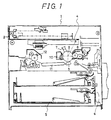
- a document reading section 2 for reading an original document is provided in the upper part of a main body 1, and below the document reading section 2 is provided an exposure section 4 which exposes a photoconductor drum 3, the image bearing member, to light corresponding to image information read by the document reading section 2, and thereby forms an electrostatic latent image on the surface of the photoconductor drum 3.
- a paper cassette 5 containing paper to which a toner image, the developed image formed on the surface of the photoconductor drum 3, is to be transferred; and a paper feed section 6 for feeding the paper out of the paper cassette 5.
- a charger 7 for uniformly charging the surface of the photoconductor drum 3
- a developing device 8 for developing the electrostatic latent image formed by exposure at the exposure section 4
- a transfer unit 9 for transferring the toner image developed by the developing device 8 onto the paper
- a cleaning device 10 for removing residual toner remaining on the surface of the photoconductor drum 3 after transfer by the transfer unit 9.
- a transport belt 11 for transporting the paper to which the toner image has been transferred by the transfer unit 9; a fixing device 12 for fixing the thus transferred toner image to the paper transported by the transport belt 11; and a paper exit section for ejecting the paper after the toner image has been fixed to it.
- the developing device 8 contains a two-component developer consisting of toner and carrier, and comprises a stirring roller 13 for stirring the two-component developer, a feed roller 14 for feeding, for example, negatively charged toner, and a magnetic roller 15 for applying the negatively charged toner fed from the feed roller 14 onto the photoconductor drum 3 for development.
- the cleaning device 10 comprises: a cleaning blade 16 for scraping off residual toner from the surface of the photoconductor drum 3 by applying its tip end in elastically contacting relationship to the surface of the photoconductor drum 3; a first conveying member 17 formed from a conductive material for selectively conveying toner charged with the polarity proper for development out of the toner scraped off into the cleaning device 10 by the cleaning blade 16; and a second conveying member 18 formed from a conductive material for selectively conveying foreign matter and toner charged with a polarity opposite to the proper polarity out of the toner scraped off into the cleaning device 10 by the cleaning blade 16.
- the first conveying member 17 is disposed in non-contacting relationship to the photoconductor drum 3 and in close proximity to the cleaning blade 16, and a bias voltage whose polarity is opposite to the proper polarity is applied from a first bias power supply 19 to the first conveying member 17 to electrostatically attract the toner charged with the polarity opposite to the proper polarity.
- the second conveying member 18 is disposed outwardly of the first conveying member 17 in non-contacting relationship to the first conveying member 17, and a bias voltage having the same polarity as the proper polarity is applied from a second bias power supply 20 to the second conveying member 18 to electrostatically attract the oppositely charged toner and foreign matter.
- the foreign matter here refers to oppositely charged toner and carrier delivered from the developing device 8 and paper dust, rosin, talc, etc. adhered from the paper onto the surface of the photoconductor drum 3 in the transfer area of the transfer unit 9.
- the first conveying member 17 and second conveying member 18 are each constructed from a spiral coil or a screw auger or the like, which rotates to convey toner or foreign matter in a direction parallel to its axis of rotation.
- the cleaning blade 16 scrapes off the residual toner from the surface of the photoconductor drum 3 into the cleaning device 10.
- the scraped off toner is first conveyed with the rotation of the first conveying member 17 to which the bias voltage whose polarity is opposite to the proper polarity is applied from the first bias power supply 19.
- the toner charged with the proper polarity is electrostatically attracted to the first conveying member 17, conveyed in the direction parallel to its axis of rotation, and returned back to the developing device 8 from the cleaning device 10 through a conveying pipe containing a toner conveying spiral coil inside itself.
- the second conveying member 18 is supplied with a bias voltage having the same polarity as the proper polarity by the second bias power supply 20, the oppositely charged toner and foreign matter (carrier, paper dust, etc.) are electrostatically attracted to the second conveying member 18, conveyed in the direction parallel to its axis of rotation, and collected in a collecting container (not shown) for storing.
- the foreign matter is disposed by replacing the collecting container.
- the second conveying member 18 is disposed farther away from the photoconductor drum 3 than the first conveying member 17 is, as described above, of the residual toner scraped off the photoconductor drum 3 by the cleaning blade 16, the oppositely charged toner and foreign matter are quickly conveyed toward the second conveying member 18 disposed away from the photoconductor drum 3 and away from the photoconductor drum 3, reducing the time during which the carrier and other foreign matter stay in the vicinity of the photoconductor drum 3 and thus minimizing the risk of the photoconductor drum 3 being scratched with the carrier, etc.
- first conveying member 17 and second conveying member 18 are laterally arranged, but instead, they may be vertically arranged as shown in Fig. 3.
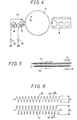
- the rotating directions of the first conveying member 17 and second conveying member 18 will be explained with reference to Fig. 4.
- the first conveying member 17 is driven to rotate in the same direction as the photoconductor drum 3, while the second conveying member 18 is driven to rotate in the opposite direction to that of the photoconductor drum 3 (the first conveying member 17); as a result, the residual toner is efficiently stirred between the first conveying member 17 and second conveying member 18, so that the toners and foreign matter electrostatically attracted to the respective conveying members can be sorted out efficiently.
- the rotational speed X1 of the first conveying member 17 is made equal to or faster than the rotational speed X0 of the photoconductor drum 3, not only can the amount of residual toner collected by the cleaning blade 16 be held within the conveying capacity of the first conveying member 17 but, of the residual toner scraped off by the cleaning blade 16, excess toner not conveyed by the first conveying member 17 can be prevented from accumulating on the cleaning blade 16 or on the first conveying member 17, thus preventing excess toner buildup and agglomeration and maintaining the desired cleaning effect for an extended period of time.
- the rotational speed X1 of the first conveying member 17 at this time be set two to four times the rotational speed X0 of the photoconductor drum 3.
- the rotational speed X2 of the second conveying member 18 is made slower than the rotational speed X0 of the photoconductor drum 3.
- the second conveying member 18 can handle aconveying process if it is rotated at slow speed; this allows a reduction in the load necessary to drive the second conveying member 18, allowing the load of the entire apparatus to be reduced.
- first conveying member 17 and the second conveying member 18 are each constructed from a spiral coil or a screw auger.
- a pitch P1 of the first conveying member 17 is set larger than a pitch P2 of the second conveying member 18 (P1 > P2), and a valid diameter d1 of the first conveying member 17 is also set larger than a valid diameter d2 of the second conveying member 18 (d1 > d2).
- the conveying capacity of the first conveying member 17 can be made larger than the conveying capacity of the second conveying member 18; this prevents toner accumulation near the photoconductor drum 3 and improves the collection efficiency of the first conveying member 17 for collecting reusable toner.
- either one of the pitch or the valid diameter of the first conveying member 17 may be set larger than the pitch or the valid diameter of the second conveying member 18; in that case also, the conveying capacity of the first conveying member 17 can be made larger than the conveying capacity of the second conveying member 18.
- the conveying capacity of the first conveying member 17 can be made larger than the conveying capacity of the second conveying member 18, as in the above case.
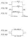
- the bias voltage application timing for the first conveying member 17 and second conveying member 18 is synchronized to the main driving signal for rotationally driving the first conveying member 17 and second conveying member 18.
- the toner and foreign matter adhering to the first conveying member 17 and second conveying member 18 can be removed by abrupt changes in electrostatic force associated with the start/stop action; this serves to eliminate the toner, etc. clinging to the first conveying member 17 and second conveying member 18 and prevent the conveying capacity from dropping due to the adherence of toner to the conveying members, while at the same time preventing accumulation or agglomeration of toner or foreign matter in a conveying passage.
- bias voltage applied to the first conveying member 17 at +400 to +450 V and the bias voltage applied to the second conveying member 18 at -400 to -450 V, as shown in Figs. 8A and 8B, that is, by setting the bias voltages applied to the first conveying member 17 and second conveying member 18 equal in magnitude but different only in polarity, application of the bias voltages can be controlled using simple circuitry.
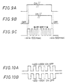
- Bias voltages may be applied in intermittent fashion to the first conveying member 17 and second conveying member 18, as shown in Figs. 9 and 10 during rotational operation of the conveying members.
- the electrostatic force acting on the conveying members varies periodically, and the resulting vibration works to remove the toner and foreign matter adhering to the first conveying member 17 and second conveying member 18; this serves to eliminate the toner, etc. clinging to the first conveying member 17 and second conveying member 18 and prevent the conveying capacity from dropping due to the adherence of toner to the conveying members, while at the same time preventing accumulation or agglomeration of toner or foreign matter in the conveying passage.
Landscapes
- Life Sciences & Earth Sciences (AREA)
- Engineering & Computer Science (AREA)
- Environmental & Geological Engineering (AREA)
- Sustainable Development (AREA)
- Physics & Mathematics (AREA)
- General Physics & Mathematics (AREA)
- Cleaning In Electrography (AREA)
Applications Claiming Priority (2)
| Application Number | Priority Date | Filing Date | Title |
|---|---|---|---|
| JP30854998 | 1998-10-29 | ||
| JP30854998A JP3337429B2 (ja) | 1998-10-29 | 1998-10-29 | クリーニング装置 |
Publications (3)
| Publication Number | Publication Date |
|---|---|
| EP0997797A2 true EP0997797A2 (de) | 2000-05-03 |
| EP0997797A3 EP0997797A3 (de) | 2001-08-16 |
| EP0997797B1 EP0997797B1 (de) | 2006-01-18 |
Family
ID=17982376
Family Applications (1)
| Application Number | Title | Priority Date | Filing Date |
|---|---|---|---|
| EP99308482A Expired - Lifetime EP0997797B1 (de) | 1998-10-29 | 1999-10-27 | Reinigungsvorrichtung |
Country Status (4)
| Country | Link |
|---|---|
| US (1) | US6157807A (de) |
| EP (1) | EP0997797B1 (de) |
| JP (1) | JP3337429B2 (de) |
| DE (1) | DE69929501T2 (de) |
Cited By (1)
| Publication number | Priority date | Publication date | Assignee | Title |
|---|---|---|---|---|
| JP2017053993A (ja) * | 2015-09-09 | 2017-03-16 | 京セラドキュメントソリューションズ株式会社 | トナー搬送装置およびこれを備える画像形成装置 |
Families Citing this family (5)
| Publication number | Priority date | Publication date | Assignee | Title |
|---|---|---|---|---|
| JP4815816B2 (ja) * | 2005-02-14 | 2011-11-16 | 富士ゼロックス株式会社 | 画像形成装置 |
| US7310494B2 (en) * | 2005-08-30 | 2007-12-18 | Lexmark International, Inc. | Developing agent transport and storage |
| JP2008129513A (ja) * | 2006-11-24 | 2008-06-05 | Brother Ind Ltd | 画像形成装置 |
| DE102009038482A1 (de) | 2009-08-21 | 2011-04-28 | OCé PRINTING SYSTEMS GMBH | Verfahren zur Reinigung eines Tonerbildträgers von Resttoner bei einem elektrografischen Druckgerät |
| JP2013029724A (ja) * | 2011-07-29 | 2013-02-07 | Fuji Xerox Co Ltd | トナー回収装置及び画像形成装置 |
Family Cites Families (6)
| Publication number | Priority date | Publication date | Assignee | Title |
|---|---|---|---|---|
| DE3422948C2 (de) * | 1983-06-20 | 1986-08-14 | Ricoh Co., Ltd., Tokio/Tokyo | Verfahren und Vorrichtung zum Sammeln von nicht-übertragenem Trockenentwickler in einem elektrophotographischen Kopiergerät |
| US4601569A (en) * | 1984-12-19 | 1986-07-22 | Eastman Kodak Company | Apparatus for cleaning a photoconductor |
| US4875081A (en) * | 1988-10-24 | 1989-10-17 | Xerox Corporation | Electrophotographic device having a.c. biased cleaning member |
| US4989047A (en) * | 1989-12-11 | 1991-01-29 | Xerox Corporation | Cleaning apparatus for the reduction of agglomeration-caused spotting |
| US5416572A (en) * | 1994-01-03 | 1995-05-16 | Xerox Corporation | Cleaning apparatus for an electrophotographic printing machine |
| JPH09251264A (ja) * | 1996-01-12 | 1997-09-22 | Canon Inc | クリーニング装置とこのクリーニング装置を有するプロセスカートリッジ、及びこのカートリッジを用いる画像形成装置 |
-
1998
- 1998-10-29 JP JP30854998A patent/JP3337429B2/ja not_active Expired - Fee Related
-
1999
- 1999-10-27 EP EP99308482A patent/EP0997797B1/de not_active Expired - Lifetime
- 1999-10-27 US US09/428,248 patent/US6157807A/en not_active Expired - Lifetime
- 1999-10-27 DE DE69929501T patent/DE69929501T2/de not_active Expired - Lifetime
Cited By (1)
| Publication number | Priority date | Publication date | Assignee | Title |
|---|---|---|---|---|
| JP2017053993A (ja) * | 2015-09-09 | 2017-03-16 | 京セラドキュメントソリューションズ株式会社 | トナー搬送装置およびこれを備える画像形成装置 |
Also Published As
| Publication number | Publication date |
|---|---|
| JP2000132037A (ja) | 2000-05-12 |
| EP0997797A3 (de) | 2001-08-16 |
| DE69929501D1 (de) | 2006-04-06 |
| US6157807A (en) | 2000-12-05 |
| JP3337429B2 (ja) | 2002-10-21 |
| DE69929501T2 (de) | 2006-08-31 |
| EP0997797B1 (de) | 2006-01-18 |
Similar Documents
| Publication | Publication Date | Title |
|---|---|---|
| US5610697A (en) | Electrophotographic apparatus capable of preventing image deterioration attributable to residual toner particles | |
| US5499090A (en) | Image forming apparatus having a toner recycling mechanism | |
| JP2002099143A (ja) | 現像装置およびこれを備える画像形成装置 | |
| US6157807A (en) | Cleaning device with electrically biased conveying members for collecting, separating and reusing developer | |
| JPH09288426A (ja) | 画像形成装置 | |
| JP2001242759A (ja) | クリーニング装置 | |
| JPH0822201A (ja) | 画像形成装置ならびにそれの転写搬送手段の清掃方法 | |
| JP2001100516A (ja) | 現像装置及びこれを用いた画像形成装置 | |
| JPH0736342A (ja) | クリーニング装置 | |
| JPH0611970A (ja) | 画像形成装置の現像装置 | |
| JP3363349B2 (ja) | 画像形成装置 | |
| JP3434413B2 (ja) | 画像形成装置 | |
| JP3592576B2 (ja) | クリーニング装置及び画像形成装置 | |
| JP2002023578A (ja) | 画像形成装置 | |
| JP2005181570A (ja) | クリーニング装置及び画像形成装置 | |
| JP3599293B2 (ja) | 画像形成装置における再利用トナー回収方法及びその装置 | |
| JP3099924B2 (ja) | 画像形成装置におけるトナー回収方法 | |
| JP3400246B2 (ja) | 画像形成方法及びその装置 | |
| JP2000284598A (ja) | 現像装置 | |
| JP3234756B2 (ja) | 画像形成装置 | |
| JP3110596B2 (ja) | 分離装置及び画像形成装置 | |
| JP2001134157A (ja) | 画像形成装置 | |
| JPH07104578A (ja) | トナーのリサイクル現像装置 | |
| JP2001066961A (ja) | 画像形成装置 | |
| JP2001066959A (ja) | クリーニング装置 |
Legal Events
| Date | Code | Title | Description |
|---|---|---|---|
| PUAI | Public reference made under article 153(3) epc to a published international application that has entered the european phase |
Free format text: ORIGINAL CODE: 0009012 |
|
| AK | Designated contracting states |
Kind code of ref document: A2 Designated state(s): DE FR GB |
|
| AX | Request for extension of the european patent |
Free format text: AL;LT;LV;MK;RO;SI |
|
| PUAL | Search report despatched |
Free format text: ORIGINAL CODE: 0009013 |
|
| AK | Designated contracting states |
Kind code of ref document: A3 Designated state(s): AT BE CH CY DE DK ES FI FR GB GR IE IT LI LU MC NL PT SE |
|
| AX | Request for extension of the european patent |
Free format text: AL;LT;LV;MK;RO;SI |
|
| RIC1 | Information provided on ipc code assigned before grant |
Free format text: 7G 03G 21/10 A, 7G 03G 21/00 B |
|
| 17P | Request for examination filed |
Effective date: 20011126 |
|
| 17Q | First examination report despatched |
Effective date: 20020301 |
|
| AKX | Designation fees paid |
Free format text: DE FR GB |
|
| GRAP | Despatch of communication of intention to grant a patent |
Free format text: ORIGINAL CODE: EPIDOSNIGR1 |
|
| GRAL | Information related to payment of fee for publishing/printing deleted |
Free format text: ORIGINAL CODE: EPIDOSDIGR3 |
|
| GRAS | Grant fee paid |
Free format text: ORIGINAL CODE: EPIDOSNIGR3 |
|
| GRAS | Grant fee paid |
Free format text: ORIGINAL CODE: EPIDOSNIGR3 |
|
| GRAA | (expected) grant |
Free format text: ORIGINAL CODE: 0009210 |
|
| AK | Designated contracting states |
Kind code of ref document: B1 Designated state(s): DE FR GB |
|
| REG | Reference to a national code |
Ref country code: GB Ref legal event code: FG4D |
|
| REF | Corresponds to: |
Ref document number: 69929501 Country of ref document: DE Date of ref document: 20060406 Kind code of ref document: P |
|
| ET | Fr: translation filed | ||
| PLBE | No opposition filed within time limit |
Free format text: ORIGINAL CODE: 0009261 |
|
| STAA | Information on the status of an ep patent application or granted ep patent |
Free format text: STATUS: NO OPPOSITION FILED WITHIN TIME LIMIT |
|
| 26N | No opposition filed |
Effective date: 20061019 |
|
| REG | Reference to a national code |
Ref country code: FR Ref legal event code: PLFP Year of fee payment: 17 |
|
| REG | Reference to a national code |
Ref country code: FR Ref legal event code: PLFP Year of fee payment: 18 |
|
| REG | Reference to a national code |
Ref country code: FR Ref legal event code: PLFP Year of fee payment: 19 |
|
| PGFP | Annual fee paid to national office [announced via postgrant information from national office to epo] |
Ref country code: FR Payment date: 20171024 Year of fee payment: 19 Ref country code: DE Payment date: 20171019 Year of fee payment: 19 |
|
| PGFP | Annual fee paid to national office [announced via postgrant information from national office to epo] |
Ref country code: GB Payment date: 20171019 Year of fee payment: 19 |
|
| REG | Reference to a national code |
Ref country code: DE Ref legal event code: R119 Ref document number: 69929501 Country of ref document: DE |
|
| GBPC | Gb: european patent ceased through non-payment of renewal fee |
Effective date: 20181027 |
|
| PG25 | Lapsed in a contracting state [announced via postgrant information from national office to epo] |
Ref country code: DE Free format text: LAPSE BECAUSE OF NON-PAYMENT OF DUE FEES Effective date: 20190501 |
|
| PG25 | Lapsed in a contracting state [announced via postgrant information from national office to epo] |
Ref country code: FR Free format text: LAPSE BECAUSE OF NON-PAYMENT OF DUE FEES Effective date: 20181031 |
|
| PG25 | Lapsed in a contracting state [announced via postgrant information from national office to epo] |
Ref country code: GB Free format text: LAPSE BECAUSE OF NON-PAYMENT OF DUE FEES Effective date: 20181027 |