EP0998037B1 - Verlustarmes Oberflächenwellenfilter auf einem schnittoptimierten Quarzsubstrat - Google Patents
Verlustarmes Oberflächenwellenfilter auf einem schnittoptimierten Quarzsubstrat Download PDFInfo
- Publication number
- EP0998037B1 EP0998037B1 EP99402626A EP99402626A EP0998037B1 EP 0998037 B1 EP0998037 B1 EP 0998037B1 EP 99402626 A EP99402626 A EP 99402626A EP 99402626 A EP99402626 A EP 99402626A EP 0998037 B1 EP0998037 B1 EP 0998037B1
- Authority
- EP
- European Patent Office
- Prior art keywords
- axis
- cut
- angle
- quartz
- coefficient
- Prior art date
- Legal status (The legal status is an assumption and is not a legal conclusion. Google has not performed a legal analysis and makes no representation as to the accuracy of the status listed.)
- Expired - Lifetime
Links
- VYPSYNLAJGMNEJ-UHFFFAOYSA-N silicon dioxide Inorganic materials O=[Si]=O VYPSYNLAJGMNEJ-UHFFFAOYSA-N 0.000 title claims description 36
- 239000010453 quartz Substances 0.000 title claims description 35
- 239000000758 substrate Substances 0.000 title claims description 18
- 238000010897 surface acoustic wave method Methods 0.000 title claims description 15
- 229910052782 aluminium Inorganic materials 0.000 claims description 9
- XAGFODPZIPBFFR-UHFFFAOYSA-N aluminium Chemical compound [Al] XAGFODPZIPBFFR-UHFFFAOYSA-N 0.000 claims description 9
- 230000026683 transduction Effects 0.000 claims description 8
- 238000010361 transduction Methods 0.000 claims description 8
- 230000004907 flux Effects 0.000 claims description 3
- 238000003491 array Methods 0.000 claims description 2
- 230000001902 propagating effect Effects 0.000 claims description 2
- 239000004411 aluminium Substances 0.000 claims 1
- 238000005520 cutting process Methods 0.000 description 12
- 239000000463 material Substances 0.000 description 8
- 238000001465 metallisation Methods 0.000 description 8
- 230000008878 coupling Effects 0.000 description 7
- 238000010168 coupling process Methods 0.000 description 7
- 238000005859 coupling reaction Methods 0.000 description 7
- 238000000375 direct analysis in real time Methods 0.000 description 5
- 238000012063 dual-affinity re-targeting Methods 0.000 description 5
- 230000008901 benefit Effects 0.000 description 4
- 239000013078 crystal Substances 0.000 description 4
- 238000004519 manufacturing process Methods 0.000 description 4
- 238000009826 distribution Methods 0.000 description 3
- 230000000694 effects Effects 0.000 description 3
- 229910052751 metal Inorganic materials 0.000 description 3
- 239000002184 metal Substances 0.000 description 3
- 238000003780 insertion Methods 0.000 description 2
- 230000037431 insertion Effects 0.000 description 2
- 230000004044 response Effects 0.000 description 2
- 230000035945 sensitivity Effects 0.000 description 2
- 102100028892 Cardiotrophin-1 Human genes 0.000 description 1
- 101000916283 Homo sapiens Cardiotrophin-1 Proteins 0.000 description 1
- 241001080024 Telles Species 0.000 description 1
- 230000007547 defect Effects 0.000 description 1
- 238000000151 deposition Methods 0.000 description 1
- 230000008021 deposition Effects 0.000 description 1
- 238000010586 diagram Methods 0.000 description 1
- 238000005538 encapsulation Methods 0.000 description 1
- 238000004146 energy storage Methods 0.000 description 1
- 238000005457 optimization Methods 0.000 description 1
- 230000009467 reduction Effects 0.000 description 1
- 230000007306 turnover Effects 0.000 description 1
- 229910021489 α-quartz Inorganic materials 0.000 description 1
Images


Classifications
-
- H—ELECTRICITY
- H03—ELECTRONIC CIRCUITRY
- H03H—IMPEDANCE NETWORKS, e.g. RESONANT CIRCUITS; RESONATORS
- H03H9/00—Networks comprising electromechanical or electro-acoustic elements; Electromechanical resonators
- H03H9/02—Details
- H03H9/02535—Details of surface acoustic wave devices
- H03H9/02543—Characteristics of substrate, e.g. cutting angles
- H03H9/02551—Characteristics of substrate, e.g. cutting angles of quartz substrates
-
- H—ELECTRICITY
- H03—ELECTRONIC CIRCUITRY
- H03H—IMPEDANCE NETWORKS, e.g. RESONANT CIRCUITS; RESONATORS
- H03H9/00—Networks comprising electromechanical or electro-acoustic elements; Electromechanical resonators
- H03H9/15—Constructional features of resonators consisting of piezoelectric or electrostrictive material
- H03H9/21—Crystal tuning forks
- H03H9/215—Crystal tuning forks consisting of quartz
Definitions
- the field of the invention is that of wave devices acoustic and in particular that of filters or resonators, produced using surface of a piezoelectric material substrate.
- the choice of a material and its cut to make a device to surface acoustic waves are generally done according to two criteria: the piezoelectric coupling coefficient which characterizes the relative band maximum that we know how to make and the behavior of the material as a function of the temperature.
- the piezoelectric coupling coefficient which characterizes the relative band maximum that we know how to make
- the behavior of the material as a function of the temperature.
- the temperature varies, the material gets dilates and its elastic coefficients vary resulting in variations in the speed of propagation of surface waves and therefore of the frequency of devices.
- Quartz has been a material used for a very long time for surface wave filters.
- the cut used in general is the so-called ST cut (MB. Schultz, B.J. Matzinger, M.G. Holland, “Temperature dependence of surface acoustic wave velocity on ⁇ quartz ", Journal of Applied Physics, Flight. 41, n ° 7, pp. 2755-2765, (1970)).
- the cutting angles ⁇ , ⁇ and ⁇ are defined according to the IEEE standard (Standard on piezoelectricity Std 176-1949, Proc. IRE, vol. 37, pp. 1378-1395 (1949)).
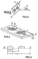
- FIG. 1 shows a cutting plate (YX), that is to say that the normal to the cutting plane is the Y axis and that the direction of propagation is the X axis.
- w along the width of the plate
- I along its length, therefore the direction of propagation
- t perpendicular to the plate
- a section and a propagation angle are defined starting from the section (YX) and applying three successive rotations.
- the rotation around w being by an angle ⁇
- the rotation around I by an angle ⁇
- that around t by an angle ⁇ The propagation takes place in the direction I of the turned plate.
- the section plane is therefore entirely defined by the first two angles ⁇ and ⁇ ( Figure 2a) while the third ⁇ defines a particular direction in this plane and therefore for surface waves the direction of propagation used ( Figure 2b).
- the initial axis coordinate system is (XYZ), it becomes after the first rotation (X'Y'Z ') and (X "Y” Z ") after the second rotation and (X "'Y"' Z "') after the third rotation.
- This simple rotation cut has the advantage of having, for Rayleigh waves, a variation in frequency with temperature parabolic with a reversal point at around twenty five degrees Celsius (25 ° C), i.e. often in the middle of the temperature range operation for filters.
- the coupling coefficient for this cut is relatively low (around 0.12%).
- the reflection coefficient is limited by the maximum thickness of the electrodes that it is possible to achieve.
- sensitivity to uncertainties technological is all the more strong that the metallization thickness is strong, which limits the thickness usable in practice.
- the subject of the invention is a wave device surface acoustics using a quartz substrate and reflections for which the reflection coefficient used is improved, while retaining the other properties of the material, through an optimized choice of the quartz cut used as a piezoelectric substrate.
- all the transduction centers and all the reflection centers can belong to the same set of electrodes interdigitated.
- certain centers of reflection can belong to a separate network of electrodes.
- the device can also include reflection centers from an engraved network in the quartz substrate.
- the metallizations used in a device according to the invention are made of aluminum.
- the acoustic wave device surface can be a unidirectional filter of type SPUDT or RSPUDT.
- the ST cut of the quartz currently selected offers satisfactory performance in terms of coupling coefficient, curve frequency variation with temperature but the introduction then the generalization of reflective elements in new types of filters generate additional stress making the ST cut relatively less interesting when we focus on the reflection coefficient of reflector including aluminum.
- the coefficient of 1st order frequency temperature is low, typically understood between -10 ppm / ° K and +10 ppm / ° K, and an angle of flux also small, typically between -5 ° and + 5 °.
- the first condition leads to obtaining a temperature-frequency inversion temperature close to 25 ° C, which is practically sought after.
- the second condition allows an optimization of the operation surface acoustic wave devices in the smallest size possible (no offset of the transducers to catch said angle of energy flow).
- Figure 4 illustrates very schematically an example of surface acoustic wave device according to the invention and comprising transduction centers and reflection centers created using metal electrodes. More specifically, this device comprises two transducers with interdigitated electrodes 2, 3, 4, 5 and two reflectors 6 and 7 made up of networks of lines.
- the propagation direction is the direction X "'of the substrate after rotation and it is therefore the axis X" of the defined cutting plane by the angles ⁇ and ⁇ turned by an angle ⁇ .
- ⁇ 35 ° + 10 ° .sin (3 ⁇ ).
- Table I summarizes and references different cutting plans identified by the angles ⁇ and ⁇ , and associated with a direction of propagation marked by the angle ⁇ .
- the angle ⁇ and the cut ⁇ are chosen for the coincidence of strong reflection coefficients, of an energy flow angle close to 0 ° and for their inversion temperature close to 25 ° C.
- Table II summarizes the aforementioned physical parameters corresponding to the sections of Table I.
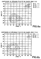
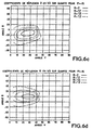
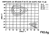
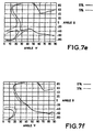
- FIGS. 6a to 6g illustrate the isovalue curves of the reflection coefficient on an aluminum obstacle of small relative thickness h / ⁇ , that is to say by considering the ratio height h to acoustic wavelength ⁇ very much lower per cent for a metallization ratio per period a / p of 50% as illustrated in FIG. 5, calculated using the simplified model based on the calculations of Datta and Hunsinger, as a function of the cutting angle ⁇ and the direction of propagation ⁇ for the various values of the cutting angle ⁇ concerned by the claims (that is to say from 0 ° to -60 ° in steps of 10 °).
- These curves make it possible to graphically specify the zones with a high reflection coefficient R which is the subject of the invention.
- the advantage of using the new cut then lies in a substantial reduction in the thickness of metal necessary to make the reflective part of the resonant DART. In fact, it goes from 1400nm (14000 ⁇ ) (ST cut) to 800nm (8000 ⁇ ) for the new cut, which makes the manufacturing of the device less subject to manufacturing defects of purely technological origin.
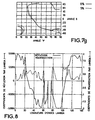
- FIG. 8 shows the spatial distribution of the reflectors R (expressed by wavelength) and the distribution of the standardized transducers T, the coefficient of an elementary reflector being 2.92%, which corresponds to a maximum of 5.84 % by wavelength.
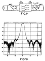
- the curve illustrated in FIG. 10 makes it possible to assess the quality of the electrical response of the filter on cut (f), with a distant rejection greater than 40 dB and losses in the band of the order of -7.5 dB.
- Figure 11 shows that the Rayleigh waves, taking into account the relative thickness of metallization used (h / ⁇ of the order of 1.67%), are compensated for the effects of temperature in the vicinity of ambient temperature, thus allowing to obtain a parabolic temperature frequency law of the filter whose inversion point is between 10 and 20 ° C.
- the second order temperature sensitivity coefficient is significantly higher than that of the ST cut (-50 ppb / ° K 2 for cut (f) against -40 ppb / ° K 2 for ST cut) but remains however in the same order of magnitude.
Landscapes
- Physics & Mathematics (AREA)
- Acoustics & Sound (AREA)
- Chemical & Material Sciences (AREA)
- Crystallography & Structural Chemistry (AREA)
- Surface Acoustic Wave Elements And Circuit Networks Thereof (AREA)
Claims (6)
- Akustische Oberflächenwellenvorrichtung, die aufweist:wobei das Substrat eine Schnittebene (X", Z") aufweist, die bezüglich der Schnittebene (X, Z) und in einem Koordinatensystem (X", Y", Z") definiert ist, wenn X, Y, Z die kristallographischen Achsen des Quarzes sind, wobei die Ausbreitungsrichtung der Wellen gemäß einer Achse X"' definiert ist, wobei eine erste Schnittebene (X', Z') durch Drehung der Ebene (X, Z) um einen Winkel ϕ um die Achse Z, definiert ist, um ein erstes Koordinatensystem (X', Y', Z') mit einer Achse Z' zu definieren, die mit der Achse Z zusammenfällt, wobei eine zweite Schnittebene (X", Z") durch Drehung der Ebene (X', Z') um einen Winkel um die Achse X' definiert ist, um ein zweites Koordinatensystem (X", Y", Z") zu definieren, wobei die Achse X" mit der Achse X' zusammenfällt, wobei die Ausbreitungsrichtung gemäß der Achse X"' durch Drehung der Achse X" in der Ebene (X", Z") um einen Winkel ψ um die Achse Y" definiert ist, dadurch gekennzeichnet, dass gilt:ein Substrat aus Quarz mit einer Ausbreitungsfläche für die akustischen Oberflächenwellen;Mittel, um Wandlungszentren und Reflexionszentren von akustischen Wellen zu bilden; liegt in einem Bereich von ±40° um -40°.cos (3ϕ)ψ liegt in einem Bereich von ±22,5° um 35°+10°.sin (3ϕ).
- Akustische Oberflächenwellenvorrichtung nach Anspruch 1, dadurch gekennzeichnet, dass gilt:
- Vorrichtung nach einem der Ansprüche 1 oder 2, dadurch gekennzeichnet, dass sie ineinander verschachtelte Elektroden aufweist, um Wandlungsund Reflexionszentren zu bilden.
- Vorrichtung nach einem der Ansprüche 1 oder 2, dadurch gekennzeichnet, dass sie außerdem Elektrodennetze aufweist, um Reflexionszentren zu bilden.
- Vorrichtung nach einem der Ansprüche 3 oder 4, dadurch gekennzeichnet, dass das Quarzsubstrat lokal eingravierte Rillen aufweist, um Wandlungszentren zu bilden.
- Vorrichtung nach einem der Ansprüche 3 bis 5, dadurch gekennzeichnet, dass die Elektroden aus Aluminium sind.
Applications Claiming Priority (2)
| Application Number | Priority Date | Filing Date | Title |
|---|---|---|---|
| FR9813665 | 1998-10-30 | ||
| FR9813665A FR2785473B1 (fr) | 1998-10-30 | 1998-10-30 | Filtre faibles pertes a ondes acoustiques de surface sur substrat de quartz de coupe optimisee |
Publications (2)
| Publication Number | Publication Date |
|---|---|
| EP0998037A1 EP0998037A1 (de) | 2000-05-03 |
| EP0998037B1 true EP0998037B1 (de) | 2004-12-15 |
Family
ID=9532202
Family Applications (1)
| Application Number | Title | Priority Date | Filing Date |
|---|---|---|---|
| EP99402626A Expired - Lifetime EP0998037B1 (de) | 1998-10-30 | 1999-10-22 | Verlustarmes Oberflächenwellenfilter auf einem schnittoptimierten Quarzsubstrat |
Country Status (9)
| Country | Link |
|---|---|
| US (1) | US6316861B1 (de) |
| EP (1) | EP0998037B1 (de) |
| JP (1) | JP4479026B2 (de) |
| KR (1) | KR100712413B1 (de) |
| CN (1) | CN1253416A (de) |
| CA (1) | CA2287093A1 (de) |
| DE (1) | DE69922615T2 (de) |
| FR (1) | FR2785473B1 (de) |
| SG (1) | SG83748A1 (de) |
Families Citing this family (23)
| Publication number | Priority date | Publication date | Assignee | Title |
|---|---|---|---|---|
| FR2811828B1 (fr) * | 2000-07-13 | 2002-10-25 | Thomson Csf | Dispositif a ondes acoustiques comprenant des domaines de polarisation alternee |
| US6744182B2 (en) * | 2001-05-25 | 2004-06-01 | Mark Branham | Piezoelectric quartz plate and method of cutting same |
| JP3675373B2 (ja) * | 2001-07-17 | 2005-07-27 | セイコーエプソン株式会社 | 発振回路の温度特性調整方法 |
| JP4079658B2 (ja) * | 2002-03-05 | 2008-04-23 | 株式会社リコー | 2値化ウォブル信号を生成する回路、ライトクロック生成回路、2値化ウォブル信号を生成する方法、ライトクロック生成方法及び光ディスク装置 |
| FR2837636B1 (fr) * | 2002-03-19 | 2004-09-24 | Thales Sa | Dispositif a ondes acoustiques d'interface en tantalate de lithium |
| JP4069773B2 (ja) * | 2003-03-19 | 2008-04-02 | セイコーエプソン株式会社 | 圧電振動片、圧電振動子および圧電デバイス |
| JP2005204275A (ja) * | 2003-12-12 | 2005-07-28 | Seiko Epson Corp | 弾性表面波素子片およびその製造方法並びに弾性表面波装置 |
| FR2864618B1 (fr) * | 2003-12-24 | 2006-03-03 | Temex Sa | Capteur de temperature ou de temperature et de pression interrogeable a distance |
| JP4569447B2 (ja) * | 2005-11-18 | 2010-10-27 | エプソントヨコム株式会社 | 弾性表面波素子片および弾性表面波デバイス |
| FR2907284B1 (fr) * | 2006-10-17 | 2008-12-19 | Senseor Soc Par Actions Simpli | Procede de fabrication collective de capteurs sans calibrage a base de dispositif a ondes acoustiques |
| FR2917918B1 (fr) * | 2007-06-19 | 2010-03-12 | Senseor | Resonateur a ondes de surface a resonance parasite reduite |
| FR2925696B1 (fr) * | 2007-12-21 | 2011-05-06 | Senseor | Capteur passif a ondes de surface comportant une antenne integree et applications medicales utilisant ce type de capteur passif |
| WO2010029762A1 (ja) * | 2008-09-12 | 2010-03-18 | 国立大学法人山梨大学 | ラム波型弾性波素子 |
| JP4864114B2 (ja) * | 2009-04-14 | 2012-02-01 | 日本電波工業株式会社 | 水晶振動子 |
| FR2951335A1 (fr) | 2009-10-09 | 2011-04-15 | Senseor | Transpondeur a modes resonants couples integrant une charge variable |
| FR2958417B1 (fr) | 2010-04-06 | 2012-03-23 | Senseor | Procede d'interrogation rapide de capteurs d'ondes elastiques |
| CN107003302B (zh) * | 2014-09-15 | 2021-11-05 | Qorvo美国公司 | 通过氧化还原耦合的质量检测 |
| FR3100405B1 (fr) * | 2019-09-04 | 2021-12-31 | Frecnsys | Capteur à ondes acoustiques différentiel |
| KR102935246B1 (ko) * | 2021-02-20 | 2026-03-05 | 스펙트론 (선전) 테크놀로지스 씨오., 엘티디 | 공진 장치 및 음향 필터 |
| FR3120489B1 (fr) * | 2021-03-03 | 2023-10-20 | Frecnsys | Dispositif capteur à ondes acoustiques à deux ports |
| FR3120488B1 (fr) * | 2021-03-03 | 2023-09-15 | Frecnsys | Dispositif capteur a ondes acoustiques de surface |
| US20230336156A1 (en) * | 2022-02-28 | 2023-10-19 | The Regents Of The University Of Colorado, A Body Corporate | Minimally diffracting surface-acoustic-wave resonator |
| CN117928766A (zh) * | 2023-08-22 | 2024-04-26 | 南方电网数字电网研究院股份有限公司 | 一种声表面波温度传感器 |
Family Cites Families (14)
| Publication number | Priority date | Publication date | Assignee | Title |
|---|---|---|---|---|
| US4323809A (en) * | 1979-12-19 | 1982-04-06 | The United States Of America As Represented By The Secretary Of The Air Force | Surface acoustic wave substrate having orthogonal temperature compensated propagation directions and device applications |
| FR2483076A1 (fr) * | 1980-05-23 | 1981-11-27 | Quartz & Electronique | Sonde de temperature utilisant une lame de quartz |
| JPS5773513A (en) * | 1980-10-27 | 1982-05-08 | Yasutaka Shimizu | Surface acoustic wave device |
| US4701661A (en) * | 1985-05-28 | 1987-10-20 | Frequency Electronics, Inc. | Piezoelectric resonators having a lateral field excited SC cut quartz crystal element |
| US4670680A (en) * | 1986-07-29 | 1987-06-02 | R. F. Monolithics, Inc. | Doubly rotated orientations of cut angles for quartz crystal for novel surface acoustic wave devices |
| FR2628265B1 (fr) * | 1987-03-06 | 1990-12-21 | Thomson Csf | Antenne directive a transducteurs multiples notamment pour sonar |
| FR2682833B1 (fr) * | 1991-10-18 | 1993-12-03 | Thomson Csf | Filtre a ondes de surface et a trajet acoustique replie. |
| JPH05345201A (ja) * | 1992-06-17 | 1993-12-27 | Mitsubishi Heavy Ind Ltd | 多軸自動盤 |
| US5703427A (en) * | 1993-03-19 | 1997-12-30 | Thomson-Csf | Surface-wave distributed acoustic reflection transducer and filter including such a transducer |
| RU2099857C1 (ru) * | 1996-01-10 | 1997-12-20 | Наталья Федоровна Науменко | Высокочастотное устройство на поверхностных акустических волнах |
| JPH10200370A (ja) * | 1997-01-10 | 1998-07-31 | Murata Mfg Co Ltd | 弾性表面波フィルタ |
| JP3339350B2 (ja) * | 1997-02-20 | 2002-10-28 | 株式会社村田製作所 | 弾性表面波装置 |
| FR2762458B1 (fr) * | 1997-04-18 | 1999-07-09 | Thomson Csf | Dispositif a ondes acoustiques de surface a couplage par proximite a entrees/sorties differentielles |
| US6031315A (en) * | 1997-07-16 | 2000-02-29 | Sawtek Inc. | Optimal cut for saw devices on quartz |
-
1998
- 1998-10-30 FR FR9813665A patent/FR2785473B1/fr not_active Expired - Fee Related
-
1999
- 1999-10-19 SG SG9905193A patent/SG83748A1/en unknown
- 1999-10-19 US US09/420,942 patent/US6316861B1/en not_active Expired - Lifetime
- 1999-10-21 CA CA002287093A patent/CA2287093A1/fr not_active Abandoned
- 1999-10-22 DE DE69922615T patent/DE69922615T2/de not_active Expired - Lifetime
- 1999-10-22 EP EP99402626A patent/EP0998037B1/de not_active Expired - Lifetime
- 1999-10-28 KR KR1019990047154A patent/KR100712413B1/ko not_active Expired - Fee Related
- 1999-10-29 CN CN99122167A patent/CN1253416A/zh active Pending
- 1999-10-29 JP JP30886599A patent/JP4479026B2/ja not_active Expired - Fee Related
Also Published As
| Publication number | Publication date |
|---|---|
| KR20000029388A (ko) | 2000-05-25 |
| KR100712413B1 (ko) | 2007-04-27 |
| FR2785473A1 (fr) | 2000-05-05 |
| CN1253416A (zh) | 2000-05-17 |
| US6316861B1 (en) | 2001-11-13 |
| SG83748A1 (en) | 2001-10-16 |
| DE69922615D1 (de) | 2005-01-20 |
| JP4479026B2 (ja) | 2010-06-09 |
| JP2000151352A (ja) | 2000-05-30 |
| EP0998037A1 (de) | 2000-05-03 |
| DE69922615T2 (de) | 2005-12-15 |
| CA2287093A1 (fr) | 2000-04-30 |
| FR2785473B1 (fr) | 2001-01-26 |
Similar Documents
| Publication | Publication Date | Title |
|---|---|---|
| EP0998037B1 (de) | Verlustarmes Oberflächenwellenfilter auf einem schnittoptimierten Quarzsubstrat | |
| CA2553861C (fr) | Structure resonante hybride | |
| EP2909932B1 (de) | Wandler mit durch synchrone anregungsstrukturen geführten volumenwellen | |
| EP1222735B1 (de) | Akustisches grenzflächenwellenfilter insbesondere für drahtlose übertragungssysteme | |
| EP2628242A1 (de) | Oberflächenschallwellen-bandpassfilter mit integrierter akustischer führung mit impedanz- und/oder modusumwandlung | |
| FR2484735A1 (fr) | Resonateur a ondes acoustiques de surface | |
| EP2301150B1 (de) | Hbar resonator mit erhöhter temperatur-stabilität | |
| FR3033462A1 (fr) | Dispositif a ondes elastiques de surface comprenant un film piezoelectrique monocristallin et un substrat cristallin, a faibles coefficients viscoelastiques | |
| FR3079667A1 (fr) | Dispositif d'onde acoustique de surface sur substrat composite | |
| FR3100405A1 (fr) | Capteur à ondes acoustiques différentiel | |
| WO2006087496A1 (fr) | Dispositif a ondes acoustiques haute frequence | |
| EP1500191B1 (de) | Bauelement mit grenzflächenschallwellen aus lithiumtantalat | |
| WO2005071375A1 (fr) | Capteur de temperature interrogeable a distance | |
| EP2291911B1 (de) | Hbar-resonator mit hohem integrationsgrad | |
| EP2156554B1 (de) | Oberflächenwellenresonator mit verminderter störresonanz | |
| FR3114931A1 (fr) | Structure réflectrice pour dispositifs à ondes acoustiques de surface (SAW) | |
| FR3120489A1 (fr) | Dispositif capteur à ondes acoustiques à deux ports | |
| FR3120488A1 (fr) | Dispositif capteur a ondes acoustiques de surface | |
| CH620801A5 (de) | ||
| FR2998420A1 (fr) | Transducteur a ondes elastiques de surface se propageant sur un substrat en niobate de lithium ou en tantalate de lithium. | |
| EP4515680A1 (de) | Elastische oberflächenwellenanordnung mit in einer piezoelektrischen schicht eingebetteten elektroden, sowie entwurf und herstellung derselben | |
| WO2025141195A1 (fr) | Dispositif à ondes élastiques | |
| WO2025141194A1 (fr) | Dispositif à ondes élastiques | |
| WO2023222282A1 (fr) | Dispositif a ondes acoustiques de surface integrant une couche mince de materiau metallique | |
| FR2492189A1 (fr) | Cellules de filtre electromecanique a resonateurs et coupleurs vibrant longitudinalement, et filtre passe-bande les incorporant |
Legal Events
| Date | Code | Title | Description |
|---|---|---|---|
| PUAI | Public reference made under article 153(3) epc to a published international application that has entered the european phase |
Free format text: ORIGINAL CODE: 0009012 |
|
| AK | Designated contracting states |
Kind code of ref document: A1 Designated state(s): DE FI FR GB IT SE |
|
| AX | Request for extension of the european patent |
Free format text: AL;LT;LV;MK;RO;SI |
|
| 17P | Request for examination filed |
Effective date: 20000927 |
|
| AKX | Designation fees paid |
Free format text: DE FI FR GB IT SE |
|
| RAP1 | Party data changed (applicant data changed or rights of an application transferred) |
Owner name: THALES |
|
| GRAP | Despatch of communication of intention to grant a patent |
Free format text: ORIGINAL CODE: EPIDOSNIGR1 |
|
| RTI1 | Title (correction) |
Free format text: LOW LOSS SURFACE ACOUSTIC WAVE FILTER ON A CUT-OPTIMISED QUARTZ SUBSTRATE |
|
| GRAS | Grant fee paid |
Free format text: ORIGINAL CODE: EPIDOSNIGR3 |
|
| GRAA | (expected) grant |
Free format text: ORIGINAL CODE: 0009210 |
|
| AK | Designated contracting states |
Kind code of ref document: B1 Designated state(s): DE FI FR GB IT SE |
|
| PG25 | Lapsed in a contracting state [announced via postgrant information from national office to epo] |
Ref country code: IT Free format text: LAPSE BECAUSE OF FAILURE TO SUBMIT A TRANSLATION OF THE DESCRIPTION OR TO PAY THE FEE WITHIN THE PRE;WARNING: LAPSES OF ITALIAN PATENTS WITH EFFECTIVE DATE BEFORE 2007 MAY HAVE OCCURRED AT ANY TIME BEFORE 2007. THE CORRECT EFFECTIVE DATE MAY BE DIFFERENT FROM THE ONE RECORDED.SCRIBED TIME-LIMIT Effective date: 20041215 Ref country code: GB Free format text: LAPSE BECAUSE OF FAILURE TO SUBMIT A TRANSLATION OF THE DESCRIPTION OR TO PAY THE FEE WITHIN THE PRESCRIBED TIME-LIMIT Effective date: 20041215 |
|
| REG | Reference to a national code |
Ref country code: GB Ref legal event code: FG4D Free format text: NOT ENGLISH |
|
| REF | Corresponds to: |
Ref document number: 69922615 Country of ref document: DE Date of ref document: 20050120 Kind code of ref document: P |
|
| PG25 | Lapsed in a contracting state [announced via postgrant information from national office to epo] |
Ref country code: SE Free format text: LAPSE BECAUSE OF FAILURE TO SUBMIT A TRANSLATION OF THE DESCRIPTION OR TO PAY THE FEE WITHIN THE PRESCRIBED TIME-LIMIT Effective date: 20050315 |
|
| GBV | Gb: ep patent (uk) treated as always having been void in accordance with gb section 77(7)/1977 [no translation filed] |
Effective date: 20041215 |
|
| PLBE | No opposition filed within time limit |
Free format text: ORIGINAL CODE: 0009261 |
|
| STAA | Information on the status of an ep patent application or granted ep patent |
Free format text: STATUS: NO OPPOSITION FILED WITHIN TIME LIMIT |
|
| 26N | No opposition filed |
Effective date: 20050916 |
|
| PGFP | Annual fee paid to national office [announced via postgrant information from national office to epo] |
Ref country code: FI Payment date: 20081030 Year of fee payment: 10 |
|
| PG25 | Lapsed in a contracting state [announced via postgrant information from national office to epo] |
Ref country code: FI Free format text: LAPSE BECAUSE OF NON-PAYMENT OF DUE FEES Effective date: 20091022 |
|
| REG | Reference to a national code |
Ref country code: FR Ref legal event code: PLFP Year of fee payment: 17 |
|
| REG | Reference to a national code |
Ref country code: FR Ref legal event code: PLFP Year of fee payment: 18 |
|
| REG | Reference to a national code |
Ref country code: FR Ref legal event code: TP Owner name: EPCOS AG, DE Effective date: 20170404 Ref country code: FR Ref legal event code: CJ Effective date: 20170404 Ref country code: FR Ref legal event code: CD Owner name: EPCOS AG, DE Effective date: 20170404 |
|
| REG | Reference to a national code |
Ref country code: FR Ref legal event code: PLFP Year of fee payment: 19 |
|
| PGFP | Annual fee paid to national office [announced via postgrant information from national office to epo] |
Ref country code: FR Payment date: 20170922 Year of fee payment: 19 |
|
| REG | Reference to a national code |
Ref country code: DE Ref legal event code: R082 Ref document number: 69922615 Country of ref document: DE Representative=s name: BARDEHLE PAGENBERG PARTNERSCHAFT MBB PATENTANW, DE Ref country code: DE Ref legal event code: R081 Ref document number: 69922615 Country of ref document: DE Owner name: SNAPTRACK, INC., SAN DIEGO, US Free format text: FORMER OWNER: EPCOS AG, 81669 MUENCHEN, DE |
|
| PGFP | Annual fee paid to national office [announced via postgrant information from national office to epo] |
Ref country code: DE Payment date: 20171027 Year of fee payment: 19 |
|
| REG | Reference to a national code |
Ref country code: FR Ref legal event code: TP Owner name: SNAPTRACK, INC., US Effective date: 20180202 |
|
| REG | Reference to a national code |
Ref country code: DE Ref legal event code: R119 Ref document number: 69922615 Country of ref document: DE |
|
| PG25 | Lapsed in a contracting state [announced via postgrant information from national office to epo] |
Ref country code: DE Free format text: LAPSE BECAUSE OF NON-PAYMENT OF DUE FEES Effective date: 20190501 |
|
| PG25 | Lapsed in a contracting state [announced via postgrant information from national office to epo] |
Ref country code: FR Free format text: LAPSE BECAUSE OF NON-PAYMENT OF DUE FEES Effective date: 20181031 |