EP0998058A2 - Système de selection d'antennes à balayage pour véhicules - Google Patents
Système de selection d'antennes à balayage pour véhicules Download PDFInfo
- Publication number
- EP0998058A2 EP0998058A2 EP99119878A EP99119878A EP0998058A2 EP 0998058 A2 EP0998058 A2 EP 0998058A2 EP 99119878 A EP99119878 A EP 99119878A EP 99119878 A EP99119878 A EP 99119878A EP 0998058 A2 EP0998058 A2 EP 0998058A2
- Authority
- EP
- European Patent Office
- Prior art keywords
- level
- switching
- logic
- signal
- level comparison
- Prior art date
- Legal status (The legal status is an assumption and is not a legal conclusion. Google has not performed a legal analysis and makes no representation as to the accuracy of the status listed.)
- Granted
Links
- 238000000034 method Methods 0.000 claims abstract description 18
- 238000012360 testing method Methods 0.000 claims abstract description 4
- 230000001960 triggered effect Effects 0.000 claims abstract description 3
- 230000002123 temporal effect Effects 0.000 claims abstract 2
- 238000001514 detection method Methods 0.000 claims description 8
- 230000000694 effects Effects 0.000 claims description 3
- 238000012546 transfer Methods 0.000 claims description 2
- 230000004913 activation Effects 0.000 claims 2
- 230000005405 multipole Effects 0.000 claims 2
- 230000035699 permeability Effects 0.000 claims 1
- 230000001771 impaired effect Effects 0.000 abstract 1
- 238000011161 development Methods 0.000 description 5
- 230000018109 developmental process Effects 0.000 description 5
- 230000007257 malfunction Effects 0.000 description 4
- 238000005259 measurement Methods 0.000 description 3
- 230000003213 activating effect Effects 0.000 description 2
- 230000001276 controlling effect Effects 0.000 description 2
- 239000011159 matrix material Substances 0.000 description 2
- 230000001360 synchronised effect Effects 0.000 description 2
- 230000001052 transient effect Effects 0.000 description 2
- 208000037656 Respiratory Sounds Diseases 0.000 description 1
- 230000006978 adaptation Effects 0.000 description 1
- 230000005540 biological transmission Effects 0.000 description 1
- 230000002596 correlated effect Effects 0.000 description 1
- 230000000875 corresponding effect Effects 0.000 description 1
- 238000013461 design Methods 0.000 description 1
- 238000010586 diagram Methods 0.000 description 1
- 208000037265 diseases, disorders, signs and symptoms Diseases 0.000 description 1
- 230000002349 favourable effect Effects 0.000 description 1
- 230000001976 improved effect Effects 0.000 description 1
- 230000000977 initiatory effect Effects 0.000 description 1
- 238000004904 shortening Methods 0.000 description 1
Images




Classifications
-
- H—ELECTRICITY
- H04—ELECTRIC COMMUNICATION TECHNIQUE
- H04B—TRANSMISSION
- H04B7/00—Radio transmission systems, i.e. using radiation field
- H04B7/02—Diversity systems; Multi-antenna system, i.e. transmission or reception using multiple antennas
- H04B7/04—Diversity systems; Multi-antenna system, i.e. transmission or reception using multiple antennas using two or more spaced independent antennas
- H04B7/08—Diversity systems; Multi-antenna system, i.e. transmission or reception using multiple antennas using two or more spaced independent antennas at the receiving station
- H04B7/0802—Diversity systems; Multi-antenna system, i.e. transmission or reception using multiple antennas using two or more spaced independent antennas at the receiving station using antenna selection
- H04B7/0805—Diversity systems; Multi-antenna system, i.e. transmission or reception using multiple antennas using two or more spaced independent antennas at the receiving station using antenna selection with single receiver and antenna switching
- H04B7/0808—Diversity systems; Multi-antenna system, i.e. transmission or reception using multiple antennas using two or more spaced independent antennas at the receiving station using antenna selection with single receiver and antenna switching comparing all antennas before reception
-
- H—ELECTRICITY
- H04—ELECTRIC COMMUNICATION TECHNIQUE
- H04B—TRANSMISSION
- H04B7/00—Radio transmission systems, i.e. using radiation field
- H04B7/02—Diversity systems; Multi-antenna system, i.e. transmission or reception using multiple antennas
- H04B7/04—Diversity systems; Multi-antenna system, i.e. transmission or reception using multiple antennas using two or more spaced independent antennas
- H04B7/08—Diversity systems; Multi-antenna system, i.e. transmission or reception using multiple antennas using two or more spaced independent antennas at the receiving station
- H04B7/0802—Diversity systems; Multi-antenna system, i.e. transmission or reception using multiple antennas using two or more spaced independent antennas at the receiving station using antenna selection
- H04B7/0805—Diversity systems; Multi-antenna system, i.e. transmission or reception using multiple antennas using two or more spaced independent antennas at the receiving station using antenna selection with single receiver and antenna switching
- H04B7/0814—Diversity systems; Multi-antenna system, i.e. transmission or reception using multiple antennas using two or more spaced independent antennas at the receiving station using antenna selection with single receiver and antenna switching based on current reception conditions, e.g. switching to different antenna when signal level is below threshold
-
- H—ELECTRICITY
- H04—ELECTRIC COMMUNICATION TECHNIQUE
- H04B—TRANSMISSION
- H04B7/00—Radio transmission systems, i.e. using radiation field
- H04B7/02—Diversity systems; Multi-antenna system, i.e. transmission or reception using multiple antennas
- H04B7/04—Diversity systems; Multi-antenna system, i.e. transmission or reception using multiple antennas using two or more spaced independent antennas
- H04B7/08—Diversity systems; Multi-antenna system, i.e. transmission or reception using multiple antennas using two or more spaced independent antennas at the receiving station
- H04B7/0802—Diversity systems; Multi-antenna system, i.e. transmission or reception using multiple antennas using two or more spaced independent antennas at the receiving station using antenna selection
- H04B7/0831—Compensation of the diversity switching process for non-uniform properties or faulty operations of the switches used in the diversity switching process
Definitions
- the invention relates to a scanning antenna diversity system for vehicles with a Multi-antenna system according to the preamble of claim 1.
- the antenna For frequency-modulated radio signals (e.g. FM reception or television sound reception) If the antenna is currently switched on, there is a reception interference due to the superimposition several partial waves with different amplitudes, phase and transit time differences on Place of receipt. The resulting drops in level are correlated with frequency interference peaks and cause signal distortion depending on the modulation content in the listening frequency range. The minimum test time therefore corresponds to the fault detection time.
- the fault detector detects in the event of a fault, the diversity processor initiates switching and the further antenna signals and possibly their linear combinations formed in an antenna matrix are checked. If all available RF signals have interference, all RF signals are continuously switched through to the receiver. That I this search process repeated in quick succession, superimposed on the received signal on the NF level a perceptible interference signal in the form of a 'crackle'.
- the object of the invention is therefore in a scanning antenna diversity system Generic type of measures to develop, the forwarding and subsequently of reducing the associated interference.
- the advantages that can be achieved with the invention are that among the diversity processor with regard to the interference signals to be selected, always the one at any time Receive signal is available, which is due to the preselection at any time delivers the highest level from the available received signals and consequently with a lower one Probability of having faults.
- the advantage brought about by the invention thus lies consequently in that a reception signal is offered for selection, the The probability of interference is smaller than for the discrete signals and the interference detection rate of the Diversity processor 4 is significantly smaller.
- it is known that with FM broadcasting Extremely strong interference can also occur with large reception signals, e.g. at the Multipath reception with large runtime differences or due to adjacent channel or Co-channel interference can be observed. Therefore it is necessary that the selection after priority and the diversity processor also maintains the maximum level signal Checks for interference and, if necessary, switches to a discrete signal.
- Fig. 2 course of the reception level from two different switching positions (S1, S2) on the the wavelength lambda-related distance and the largest signal from each of the two Switch positions at the maximum level switch position (Smax) by the level comparison device (8) is continuously determined.
- Fig. 5 example of a scanning antenna diversity system with simple logic Switching device (2), consisting of an electronic relay (31) and a addressable electronic switch (30), whose inputs to the antennas (A1..A4) are connected.
- the other inputs (in the example P2..P4) of the electronic The discrete reception signals of the antennas (A1, A2, A3) fed.
- the diversity processor (4) switches when a fault is detected in the IF signal of the Superhet receiver (3) the electronic relay (31) by one switch position further.
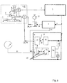
- FIG. 6 example of a scanning antenna diversity system with one from a multi-diode switch (32), a switching logic (2a) and a switching logic (2b) existing logical switching device (2).
- a switching pulse (28) occurs during a time interval (7) at the output of the diversity processor (4) the address list is one more Position processed by activating the associated diode.
- the switching logic (2a) is designed so that when the changeover signal (12) occurs, none of the diodes in the multi-diode switch (32) switches through.
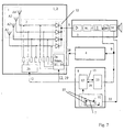
- Fig. 7 example of a scanning antenna diversity system in which synchronized with the Level comparison times (6) muting pulses (33) are formed, which one Mute circuit (34) preferably located in the low-frequency part of the receiver (3) be fed.
- a diversity processor (4) is particularly suitable Processor type that has an extremely fast fault detector.
- the processor of the type TEA 6101 has proven to be extremely powerful for this.
- the Processor responds to malfunction with an indication time of approx. 30 microseconds, which is essentially determined by the IF bandwidth of the receiver (3).
- the basic mode of operation of the present invention can be illustrated clearly with reference to FIG. 2 by considering the received signals (5) which result for two different switching positions S1 and S2 over the distance traveled, based on the wavelength lambda of the received frequency (f). This is shown in the case of an interference level that is appreciably below the median value of the two received signals (5).
- Each of the two received signals (5) has the known level drops caused by the multipath reception. Without the measures of the present invention, the diversity processor (4) would then switch to the other switching position if the signal-to-noise ratio for the received signal (5) is too small in the area of the level dips. The consequence of this is that, in the reception conditions shown by way of example in FIG.
- the larger of the two received signals (5) in addition to the discretely available switching positions S1, S2 after each of the cyclically occurring level comparison processes during the respective subsequent time interval (7) is also separate Maximum level switching position (Smax) available for selection.
- Smax Maximum level switching position
- the change itself takes place within a level comparison time (6) to be as short as possible in the interest of inaudibility after each time interval (7).
- the diversity processor (4) will generally remain in the switch position Smax for a considerably longer time than in the switch positions due to the lower probability of a fault occurring S1, S2.
- the switching frequency is thus significantly reduced.
- the cyclically repeating time intervals (7) are selected some orders of magnitude shorter than the time it takes the vehicle to cover a distance of half a wavelength of the reception frequency (f), so that the time intervals are not recognizable there in FIG. 2.
- the guide value for the minimum cycle frequency f zmin in Hz corresponds to approximately twice the driving speed in km / h.
- T p T p of approximately 20 microseconds that can be achieved taking transient effects into account
- the invention can also be advantageously applied to a large number of available switching positions with little effort.
- the received signal (5) according to the maximum level switch position (Smax) is obtained from the large number of antenna signals by the level preselection due to the constantly changing level relationships at the antennas as a result of the multipath propagation with continuously alternating.
- the associated receive signal (5) follows the level dip far less deeply after a maximum and is replaced with great frequency with a good signal-to-noise ratio from a more favorable switching position - the updated Smax.
- the level comparison device (8) in a development of the invention with a very fast measuring level comparator (10) and a logic circuit (13) for detection and for comparison, the level of the signal from the received signal (5) that is present in time derived reception signal (9) and with a periodically operating time interval generator (11) fitted.
- the time interval generator (11) triggers after each time interval (7) Level comparator (10) during the level comparison time (6) via the logic circuit (13) Level checking and selection process from such that the switching state of the logical Switching device (2) within the level comparison time (6) by a switching signal (12)
- Logic circuit (13) is switched to a further switching position and after the expiry of Level comparison time (6) in the logic circuit (13) the current maximum level switching position (Smax) is stored as an address signal (19).
- the logical switching device (2) for cyclical Advance on detection of a malfunction by the diversity processor (4) is a list of Switching position addresses, which corresponds to the current maximum level switching position (Smax) assigned address as address signal (19) by transfer from the logic circuit (13) into the logical switching device (2) is added so that it is continuously updated in this list is included. This means that this address is also used for the cyclical switching of the Received signals (5) to the receiver (3) detected.
- FIGS. 3b and 3c show examples of detailed developments of the level comparator (10) and the process during the level comparison time (6) at the end of a time interval (7) shown.
- the level comparison is initiated by the level comparison pulse (15) via the Logic circuit (13)
- the logical switching device (2) in the previous one Level comparison switched as a logic signal maximum level switching position (Smax).
- Smax logic signal maximum level switching position
- the level comparator (10) are a sample timer triggered by the level comparison pulse (15) (20) and a sample and hold decider (17) contain a short Sample time (16) (Fig.
- the timing diagram in FIG. 3c is due to the times required for the switching processes Negligibility not taken into account.
- the level comparison time (6) is practically the same twice the sample time (16).
- the sample time (16) is the measurement time, which is below Consideration of transient processes is necessary to determine the level at a Determine switch position.
- the larger level value from the last level comparison during the Determine and hold the time interval (7) with the aid of the sample and hold decider (17) and the associated address of the switching position of the logical switching device (2) in the Logic circuit (13) to save.
- Deciding on the larger of the two determined level is communicated to the logic circuit (13) as a binary signal (18) and the associated address of the switching position of the logical switching device (2) in the Logic circuit (13) is stored updated. This shortens the level comparison time (6) practically only one sample time (16), as shown in Fig. 3d.
- FIG. 5 shows a simple embodiment of a logic switching device (2), at an essential part of the logic is realized by the wiring itself.
- the logical one Switching device (2) consists of an electronic relay (31) and a addressable electronic switch (30), whose inputs to the antennas (A1..A4) are connected.
- the received signals are in accordance with the mode of operation described above (5) the antennas A1, A2 and A3 at the inputs P4, P3, P2 of the electronic relay (31) available discreetly. This via the maximum level switch position (Smax) at the output of the electronic switch (30) available maximum level signal from all antennas A1..A4 available at input P1 of the electronic relay (31) and is among the others Antenna signals always available updated.
- Smax maximum level switch position
- a special feature here is that not all antenna signals at the electronic relay (31) due to the limited Number of input connections are discretely fed to the electronic relay (31). It is obvious that by expanding the number of Input connections of the electronic relay (31) this also the signal of the antenna A4 could be added discreetly.
- Fig. 6 shows the example of a scanning antenna diversity system with one of a multi-diode switch (32), a switching logic (2a) and a switching logic (2b) existing logical switching device (2).
- the mode of action has already been explained.
- Arrangement in Fig. 5 is the list of addresses in the relay logic (2a) by the number one greater than the number of signals supplied discretely. Because of the easy availability electronic logic circuits can thus be economically integrated Realize a highly effective scanning antenna diversity system.
- this disorder can be synchronized with the Level comparison times (6) muting pulses (33) are formed, which one Mute circuit (34) preferably located in the low-frequency part of the receiver (3) be fed.
- the muting pulse (33) is in terms of its duration and that with it achieved blanking depth so that the mute during Level comparison time (6) takes place in such a way that the level comparison processes are complete are inaudible.
- a device of this type is shown by way of example in FIG. 7.
Landscapes
- Engineering & Computer Science (AREA)
- Computer Networks & Wireless Communication (AREA)
- Signal Processing (AREA)
- Radio Transmission System (AREA)
- Details Of Aerials (AREA)
Applications Claiming Priority (2)
| Application Number | Priority Date | Filing Date | Title |
|---|---|---|---|
| DE19847887A DE19847887A1 (de) | 1998-10-18 | 1998-10-18 | Scanning-Antennen-Diversity-System für Fahrzeuge |
| DE19847887 | 1998-10-18 |
Publications (3)
| Publication Number | Publication Date |
|---|---|
| EP0998058A2 true EP0998058A2 (fr) | 2000-05-03 |
| EP0998058A3 EP0998058A3 (fr) | 2000-05-10 |
| EP0998058B1 EP0998058B1 (fr) | 2003-12-17 |
Family
ID=7884777
Family Applications (1)
| Application Number | Title | Priority Date | Filing Date |
|---|---|---|---|
| EP99119878A Expired - Lifetime EP0998058B1 (fr) | 1998-10-18 | 1999-10-07 | Système de selection d'antennes à balayage pour véhicules |
Country Status (5)
| Country | Link |
|---|---|
| US (1) | US6430404B1 (fr) |
| EP (1) | EP0998058B1 (fr) |
| AT (1) | ATE256940T1 (fr) |
| DE (2) | DE19847887A1 (fr) |
| ES (1) | ES2210942T3 (fr) |
Cited By (2)
| Publication number | Priority date | Publication date | Assignee | Title |
|---|---|---|---|---|
| EP1239608A1 (fr) * | 2001-03-02 | 2002-09-11 | FUBA Automotive GmbH & Co. KG | Système en diversité de reception des signaux numeriques terrestre et/ou satellite pour voitures |
| EP1021000A3 (fr) * | 1998-12-17 | 2003-06-25 | FUBA Automotive GmbH & Co. KG | Système d'antennes de balayage en diversité pour véhicules |
Families Citing this family (15)
| Publication number | Priority date | Publication date | Assignee | Title |
|---|---|---|---|---|
| DE10209060B4 (de) * | 2002-03-01 | 2012-08-16 | Heinz Lindenmeier | Empfangsantennenanordnung für Satelliten- und/oder terrestrische Funksignale auf Fahrzeugen |
| DE10304431A1 (de) * | 2003-02-04 | 2004-08-05 | Lindenmeier, Heinz, Prof. Dr.-Ing. | Scanning-Antennen-Diversitysystem für den FM-Hörrundfunk für Fahrzeuge |
| JP4103666B2 (ja) * | 2003-04-03 | 2008-06-18 | 株式会社村田製作所 | 無線受信装置 |
| DE102006039357B4 (de) * | 2005-09-12 | 2018-06-28 | Heinz Lindenmeier | Antennendiversityanlage zum Funkempfang für Fahrzeuge |
| DE102007017478A1 (de) * | 2007-04-13 | 2008-10-16 | Lindenmeier, Heinz, Prof. Dr. Ing. | Empfangsanlage mit einer Schaltungsanordnung zur Unterdrückung von Umschaltstörungen bei Antennendiversity |
| EP2037593A3 (fr) * | 2007-07-10 | 2016-10-12 | Delphi Delco Electronics Europe GmbH | Installation de diversité d'antennes pour la réception radio à bande relativement large dans des véhicules |
| DE102007039914A1 (de) * | 2007-08-01 | 2009-02-05 | Lindenmeier, Heinz, Prof. Dr. Ing. | Antennendiversityanlage mit zwei Antennen für den Funkempfang in Fahrzeugen |
| DE102008003532A1 (de) * | 2007-09-06 | 2009-03-12 | Lindenmeier, Heinz, Prof. Dr. Ing. | Antenne für den Satellitenempfang |
| EP2207273B1 (fr) * | 2009-01-09 | 2016-01-06 | AKG Acoustics GmbH | Procédé et dispositif de réception de données audio numériques |
| PT2209221T (pt) * | 2009-01-19 | 2018-12-27 | Fuba Automotive Electronics Gmbh | Sistema de recepção para a soma de sinais de antena em fase |
| JP5310070B2 (ja) * | 2009-02-19 | 2013-10-09 | 日本電気株式会社 | 無線通信装置、無線通信方法及び無線通信システム |
| DE102009011542A1 (de) * | 2009-03-03 | 2010-09-09 | Heinz Prof. Dr.-Ing. Lindenmeier | Antenne für den Empfang zirkular in einer Drehrichtung der Polarisation ausgestrahlter Satellitenfunksignale |
| DE102009023514A1 (de) * | 2009-05-30 | 2010-12-02 | Heinz Prof. Dr.-Ing. Lindenmeier | Antenne für zirkulare Polarisation mit einer leitenden Grundfläche |
| US9276623B2 (en) * | 2013-08-20 | 2016-03-01 | Aviacomm Inc. | Cost effective multiband RF front-end architecture for mobile applications |
| US10623239B1 (en) * | 2019-02-22 | 2020-04-14 | Ford Global Technologies, Llc | Multiple antenna telematics controller radio recovery |
Family Cites Families (9)
| Publication number | Priority date | Publication date | Assignee | Title |
|---|---|---|---|---|
| JPH04358425A (ja) * | 1991-06-04 | 1992-12-11 | Sony Corp | ダイバーシティ受信装置 |
| DE4236089A1 (de) * | 1992-10-26 | 1994-04-28 | Siemens Ag | Verfahren und Anordnung zur Aktivierung von Antennen einer Funksende-/Empfangseinrichtung |
| DE4403612B4 (de) * | 1994-02-05 | 2008-10-02 | Lindenmeier, Heinz, Prof. Dr. Ing. | Schaltungsanordnung für ein Mehrantennen-Scanning-Diversitysystem für Kraftfahrzeuge |
| DE4441761A1 (de) * | 1994-11-23 | 1996-05-30 | Lindenmeier Heinz | Mehrantennen-Scanning-Diversitysystem für Fahrzeuge |
| DE19607045A1 (de) * | 1996-02-24 | 1997-08-28 | Lindenmeier Heinz | Empfangsantennen-Scanningdiversitysystem für den Meterwellenbereich für Fahrzeuge |
| DE19618333A1 (de) * | 1996-05-07 | 1997-11-13 | Lindenmeier Heinz | Schaltungsanordnung zur Funktionsprüfung mobiler Rundfunkempfangsanlagen |
| JP3139440B2 (ja) * | 1998-01-14 | 2001-02-26 | 日本電気株式会社 | アンテナおよびその受信回路異常検出装置 |
| DE19823237A1 (de) * | 1998-05-25 | 1999-12-02 | Heinz Lindenmeier | Funksystem für Fernwirkfunktionen in stehenden Fahrzeugen |
| US6275712B1 (en) * | 1999-02-26 | 2001-08-14 | Nokia Mobile Phones Ltd | Mobile station control states based on available power |
-
1998
- 1998-10-18 DE DE19847887A patent/DE19847887A1/de not_active Withdrawn
-
1999
- 1999-10-06 US US09/413,124 patent/US6430404B1/en not_active Expired - Lifetime
- 1999-10-07 DE DE59908096T patent/DE59908096D1/de not_active Expired - Lifetime
- 1999-10-07 EP EP99119878A patent/EP0998058B1/fr not_active Expired - Lifetime
- 1999-10-07 AT AT99119878T patent/ATE256940T1/de not_active IP Right Cessation
- 1999-10-07 ES ES99119878T patent/ES2210942T3/es not_active Expired - Lifetime
Cited By (2)
| Publication number | Priority date | Publication date | Assignee | Title |
|---|---|---|---|---|
| EP1021000A3 (fr) * | 1998-12-17 | 2003-06-25 | FUBA Automotive GmbH & Co. KG | Système d'antennes de balayage en diversité pour véhicules |
| EP1239608A1 (fr) * | 2001-03-02 | 2002-09-11 | FUBA Automotive GmbH & Co. KG | Système en diversité de reception des signaux numeriques terrestre et/ou satellite pour voitures |
Also Published As
| Publication number | Publication date |
|---|---|
| DE19847887A1 (de) | 2000-04-20 |
| ES2210942T3 (es) | 2004-07-01 |
| EP0998058A3 (fr) | 2000-05-10 |
| DE59908096D1 (de) | 2004-01-29 |
| EP0998058B1 (fr) | 2003-12-17 |
| US6430404B1 (en) | 2002-08-06 |
| ATE256940T1 (de) | 2004-01-15 |
Similar Documents
| Publication | Publication Date | Title |
|---|---|---|
| EP0998058B1 (fr) | Système de selection d'antennes à balayage pour véhicules | |
| EP1021000A2 (fr) | Système scanning diversitè multi d'antennes pour véhicules pour diversité de balayage. | |
| EP0201977B1 (fr) | Dispositif de réception à diversité d'antenne destiné à éliminer des perturbations de réception | |
| EP1455466B1 (fr) | Système de scanning diversifié à multiples antennes pour la fréquence FM pour des véhicules | |
| DE69125932T2 (de) | Antennendiversity-empfangseinrichtung zur beseitigung einer empfangsinterferenz beim mobilen fernsehempfang | |
| EP0521123B1 (fr) | Installation de reception en diversite comprenant deux antennes pour la reception mobile d'ondes metriques et decimetriques | |
| EP0401221B1 (fr) | Procede de reception et systeme d'antennes receptrices pour la mise en oeuvre du procede | |
| DE102008031068A1 (de) | Antennendiversityanlage für den relativ breitbandigen Funkempfang in Fahrzeugen | |
| DE3926336C2 (de) | Antennendiversity-Empfangsanlage zur Elimination von Empfangsstörungen beim mobilen Empfang von Fernsehsignalen | |
| DE19637327A1 (de) | Frequenzdiversity-Anordnung | |
| DE4403612B4 (de) | Schaltungsanordnung für ein Mehrantennen-Scanning-Diversitysystem für Kraftfahrzeuge | |
| EP1374444B1 (fr) | Procédé et dispositif permettant d'éliminer des perturbations dues aux trajets multiples dans un récepteur d'ondes électromagnétiques | |
| DE1591144B2 (de) | Empfangseinrichtung mit mindestens zwei empfaengerzuegen und einer automatischen umschalteinrichtung | |
| DE1487362B2 (de) | Verfahren und Einrichtung zur selbsttätigen Auswahl des jeweils bestmöglichen Übertragungsweges eines Nachrichtensystems | |
| DE3721918C1 (en) | Method for evaluating the suitability for reception of the frequency-modulated broadcast transmissions received in an FM broadcast receiver, and circuit arrangement for carrying out the method | |
| EP0994562A2 (fr) | Equipement permettand d'abaisser les interférences émises par un véhicule | |
| DE3938268C1 (fr) | ||
| EP0767554B1 (fr) | Récepteur avec système RDS comportant un récepteur supplémentaire | |
| DE10163653A1 (de) | Vorrichtung für ein Radarsystem | |
| DE3938269C1 (fr) | ||
| EP2071732A1 (fr) | Dispositif de commutation et procédé de transmission de signaux audio à fréquence modulée sur un récepteur FM avec Radio Data System (RDS) | |
| DE102007056327A1 (de) | Fahrzeug-Funkempfangssystem | |
| DE19925868B4 (de) | Diversity-TV-Empfangssystem | |
| EP0201681A2 (fr) | Récepteur radio mobile à commencement de balayage retardé | |
| DE4227680C2 (de) | FM-Empfänger mit RDS-Auswertung |
Legal Events
| Date | Code | Title | Description |
|---|---|---|---|
| PUAI | Public reference made under article 153(3) epc to a published international application that has entered the european phase |
Free format text: ORIGINAL CODE: 0009012 |
|
| PUAL | Search report despatched |
Free format text: ORIGINAL CODE: 0009013 |
|
| AK | Designated contracting states |
Kind code of ref document: A2 Designated state(s): AT BE CH DE DK ES FI FR GB GR IE IT LI LU MC NL PT SE |
|
| AK | Designated contracting states |
Kind code of ref document: A3 Designated state(s): AT BE CH DE DK ES FI FR GB GR IE IT LI LU MC NL PT SE |
|
| 17P | Request for examination filed |
Effective date: 20000525 |
|
| AKX | Designation fees paid |
Free format text: AT BE CH DE DK ES FI FR GB GR IE IT LI LU MC NL PT SE |
|
| GRAP | Despatch of communication of intention to grant a patent |
Free format text: ORIGINAL CODE: EPIDOSNIGR1 |
|
| GRAS | Grant fee paid |
Free format text: ORIGINAL CODE: EPIDOSNIGR3 |
|
| GRAA | (expected) grant |
Free format text: ORIGINAL CODE: 0009210 |
|
| AK | Designated contracting states |
Kind code of ref document: B1 Designated state(s): AT BE CH DE DK ES FI FR GB GR IE IT LI LU MC NL PT SE |
|
| PG25 | Lapsed in a contracting state [announced via postgrant information from national office to epo] |
Ref country code: NL Free format text: LAPSE BECAUSE OF FAILURE TO SUBMIT A TRANSLATION OF THE DESCRIPTION OR TO PAY THE FEE WITHIN THE PRESCRIBED TIME-LIMIT Effective date: 20031217 Ref country code: IE Free format text: LAPSE BECAUSE OF FAILURE TO SUBMIT A TRANSLATION OF THE DESCRIPTION OR TO PAY THE FEE WITHIN THE PRESCRIBED TIME-LIMIT Effective date: 20031217 Ref country code: FI Free format text: LAPSE BECAUSE OF FAILURE TO SUBMIT A TRANSLATION OF THE DESCRIPTION OR TO PAY THE FEE WITHIN THE PRESCRIBED TIME-LIMIT Effective date: 20031217 |
|
| REG | Reference to a national code |
Ref country code: GB Ref legal event code: FG4D Free format text: NOT ENGLISH |
|
| REG | Reference to a national code |
Ref country code: CH Ref legal event code: EP |
|
| REG | Reference to a national code |
Ref country code: IE Ref legal event code: FG4D Free format text: GERMAN |
|
| REF | Corresponds to: |
Ref document number: 59908096 Country of ref document: DE Date of ref document: 20040129 Kind code of ref document: P |
|
| PG25 | Lapsed in a contracting state [announced via postgrant information from national office to epo] |
Ref country code: GR Free format text: LAPSE BECAUSE OF FAILURE TO SUBMIT A TRANSLATION OF THE DESCRIPTION OR TO PAY THE FEE WITHIN THE PRESCRIBED TIME-LIMIT Effective date: 20040317 Ref country code: DK Free format text: LAPSE BECAUSE OF FAILURE TO SUBMIT A TRANSLATION OF THE DESCRIPTION OR TO PAY THE FEE WITHIN THE PRESCRIBED TIME-LIMIT Effective date: 20040317 |
|
| REG | Reference to a national code |
Ref country code: SE Ref legal event code: TRGR |
|
| GBT | Gb: translation of ep patent filed (gb section 77(6)(a)/1977) | ||
| NLV1 | Nl: lapsed or annulled due to failure to fulfill the requirements of art. 29p and 29m of the patents act | ||
| REG | Reference to a national code |
Ref country code: ES Ref legal event code: FG2A Ref document number: 2210942 Country of ref document: ES Kind code of ref document: T3 |
|
| REG | Reference to a national code |
Ref country code: IE Ref legal event code: FD4D |
|
| ET | Fr: translation filed | ||
| PGFP | Annual fee paid to national office [announced via postgrant information from national office to epo] |
Ref country code: SE Payment date: 20041006 Year of fee payment: 6 Ref country code: GB Payment date: 20041006 Year of fee payment: 6 |
|
| PG25 | Lapsed in a contracting state [announced via postgrant information from national office to epo] |
Ref country code: LU Free format text: LAPSE BECAUSE OF NON-PAYMENT OF DUE FEES Effective date: 20041007 Ref country code: AT Free format text: LAPSE BECAUSE OF NON-PAYMENT OF DUE FEES Effective date: 20041007 |
|
| PLBE | No opposition filed within time limit |
Free format text: ORIGINAL CODE: 0009261 |
|
| STAA | Information on the status of an ep patent application or granted ep patent |
Free format text: STATUS: NO OPPOSITION FILED WITHIN TIME LIMIT |
|
| PG25 | Lapsed in a contracting state [announced via postgrant information from national office to epo] |
Ref country code: MC Free format text: LAPSE BECAUSE OF NON-PAYMENT OF DUE FEES Effective date: 20041031 Ref country code: LI Free format text: LAPSE BECAUSE OF NON-PAYMENT OF DUE FEES Effective date: 20041031 Ref country code: CH Free format text: LAPSE BECAUSE OF NON-PAYMENT OF DUE FEES Effective date: 20041031 Ref country code: BE Free format text: LAPSE BECAUSE OF NON-PAYMENT OF DUE FEES Effective date: 20041031 |
|
| PGFP | Annual fee paid to national office [announced via postgrant information from national office to epo] |
Ref country code: ES Payment date: 20041116 Year of fee payment: 6 |
|
| 26N | No opposition filed |
Effective date: 20040920 |
|
| BERE | Be: lapsed |
Owner name: *FUBA AUTOMOTIVE G.M.B.H. & CO. K.G. Effective date: 20041031 |
|
| REG | Reference to a national code |
Ref country code: CH Ref legal event code: PL |
|
| PG25 | Lapsed in a contracting state [announced via postgrant information from national office to epo] |
Ref country code: GB Free format text: LAPSE BECAUSE OF NON-PAYMENT OF DUE FEES Effective date: 20051007 |
|
| PG25 | Lapsed in a contracting state [announced via postgrant information from national office to epo] |
Ref country code: SE Free format text: LAPSE BECAUSE OF NON-PAYMENT OF DUE FEES Effective date: 20051008 Ref country code: ES Free format text: LAPSE BECAUSE OF NON-PAYMENT OF DUE FEES Effective date: 20051008 |
|
| EUG | Se: european patent has lapsed | ||
| GBPC | Gb: european patent ceased through non-payment of renewal fee |
Effective date: 20051007 |
|
| REG | Reference to a national code |
Ref country code: ES Ref legal event code: FD2A Effective date: 20051008 |
|
| BERE | Be: lapsed |
Owner name: *FUBA AUTOMOTIVE G.M.B.H. & CO. K.G. Effective date: 20041031 |
|
| PG25 | Lapsed in a contracting state [announced via postgrant information from national office to epo] |
Ref country code: PT Free format text: LAPSE BECAUSE OF NON-PAYMENT OF DUE FEES Effective date: 20040517 |
|
| REG | Reference to a national code |
Ref country code: FR Ref legal event code: TP |
|
| PGFP | Annual fee paid to national office [announced via postgrant information from national office to epo] |
Ref country code: FR Payment date: 20141017 Year of fee payment: 16 Ref country code: DE Payment date: 20141029 Year of fee payment: 16 |
|
| PGFP | Annual fee paid to national office [announced via postgrant information from national office to epo] |
Ref country code: IT Payment date: 20141029 Year of fee payment: 16 |
|
| REG | Reference to a national code |
Ref country code: DE Ref legal event code: R119 Ref document number: 59908096 Country of ref document: DE |
|
| PG25 | Lapsed in a contracting state [announced via postgrant information from national office to epo] |
Ref country code: DE Free format text: LAPSE BECAUSE OF NON-PAYMENT OF DUE FEES Effective date: 20160503 Ref country code: IT Free format text: LAPSE BECAUSE OF NON-PAYMENT OF DUE FEES Effective date: 20151007 |
|
| REG | Reference to a national code |
Ref country code: FR Ref legal event code: ST Effective date: 20160630 |
|
| PG25 | Lapsed in a contracting state [announced via postgrant information from national office to epo] |
Ref country code: FR Free format text: LAPSE BECAUSE OF NON-PAYMENT OF DUE FEES Effective date: 20151102 |