EP0201977B1 - Dispositif de réception à diversité d'antenne destiné à éliminer des perturbations de réception - Google Patents
Dispositif de réception à diversité d'antenne destiné à éliminer des perturbations de réception Download PDFInfo
- Publication number
- EP0201977B1 EP0201977B1 EP86200803A EP86200803A EP0201977B1 EP 0201977 B1 EP0201977 B1 EP 0201977B1 EP 86200803 A EP86200803 A EP 86200803A EP 86200803 A EP86200803 A EP 86200803A EP 0201977 B1 EP0201977 B1 EP 0201977B1
- Authority
- EP
- European Patent Office
- Prior art keywords
- signal
- frequency
- antenna
- circuit
- amplitude
- Prior art date
- Legal status (The legal status is an assumption and is not a legal conclusion. Google has not performed a legal analysis and makes no representation as to the accuracy of the status listed.)
- Expired - Lifetime
Links
Images

Classifications
-
- H—ELECTRICITY
- H04—ELECTRIC COMMUNICATION TECHNIQUE
- H04B—TRANSMISSION
- H04B7/00—Radio transmission systems, i.e. using radiation field
- H04B7/02—Diversity systems; Multi-antenna system, i.e. transmission or reception using multiple antennas
- H04B7/04—Diversity systems; Multi-antenna system, i.e. transmission or reception using multiple antennas using two or more spaced independent antennas
- H04B7/08—Diversity systems; Multi-antenna system, i.e. transmission or reception using multiple antennas using two or more spaced independent antennas at the receiving station
- H04B7/0868—Hybrid systems, i.e. switching and combining
- H04B7/0874—Hybrid systems, i.e. switching and combining using subgroups of receive antennas
-
- H—ELECTRICITY
- H04—ELECTRIC COMMUNICATION TECHNIQUE
- H04B—TRANSMISSION
- H04B7/00—Radio transmission systems, i.e. using radiation field
- H04B7/02—Diversity systems; Multi-antenna system, i.e. transmission or reception using multiple antennas
- H04B7/04—Diversity systems; Multi-antenna system, i.e. transmission or reception using multiple antennas using two or more spaced independent antennas
- H04B7/08—Diversity systems; Multi-antenna system, i.e. transmission or reception using multiple antennas using two or more spaced independent antennas at the receiving station
- H04B7/0837—Diversity systems; Multi-antenna system, i.e. transmission or reception using multiple antennas using two or more spaced independent antennas at the receiving station using pre-detection combining
- H04B7/0842—Weighted combining
- H04B7/0848—Joint weighting
Definitions
- Such an antenna diversity system is known from EP-A-0036139.
- This publication discloses an antenna diversity system for mobile reception with a receiver, two antennas and a diversity processor.
- the signals of both antennas are linearly combined in the diversity processor by an addition or subtraction circuit and fed to the receiver.
- a signal is fed back to the diversity processor which corresponds to the received signal power - i.e. the power of the linearly combined antenna signals - corresponds.
- the diversity processor decides on the basis of a comparison of this signal with a threshold whether a different linear combination of the antenna signals is selected; in this case, a switch is made between addition and subtraction.
- the antenna diversity system according to EP-A 0031639 is used in a mobile handheld radio.
- Antenna diversity systems are also used to improve the radio receiver in motor vehicles.
- the dynamic behavior of the diversity system is very important. Due to the movement of the vehicle, the antenna voltages change continuously, so that an ongoing check of the signal quality is necessary. In contrast to the diversity system known from EP-A-0036139, the rapid detection of an existing disturbance in the received signal is therefore indispensable.
- the known application works slowly because a certain reception situation is long-term for a stationary application.
- the transmission property of the route between the transmitting antenna and the receiving antenna changes continuously while driving.
- the superimposition of electromagnetic waves with large, different transit times results in increased noise and distortion of the low-frequency message at the output of the frequency demodulator. In the case of stereo transmission, this effect also leads to increased crosstalk between the two stereo channels. Due to the movement of the vehicle and the directionality of the receiving antennas, adjacent channel interference and intermodulation interference change. The system is often also disturbed by electrical faults in the on-board electrical units.
- the object of the present invention is therefore to provide an antenna diversity system which avoids the disadvantage of slow interference detection and, in the event of a disturbance, selects the best antenna signal or a combination of antenna signals from a range of antenna signals.
- the system contains an FM tuner with an IF part
- the diversity processor is fed back an intermediate-frequency or high-frequency signal which corresponds to a specific linear combination derived from the antenna signals
- the diversity processor includes an AM demodulator an amplitude threshold detector connected to it and an FM demodulator with a frequency swing threshold detector connected to it and means contains, in the event of a simultaneous occurrence of an amplitude dip exceeding the amplitude threshold of the AM threshold detector and a disturbance-related frequency swing pulse exceeding the frequency swing threshold of the frequency swing threshold detector, in the intermediate-frequency or high-frequency antenna signal that has a different frequency linear combination to feed the tuner with ZF part on the input side.
- the advantages achieved by the invention are the suppression of audible reception interference even in the fast moving vehicle.
- a major advantage is that a major part of the known and frequently occurring disorders various causes can be avoided by the invention.
- These disturbances include in particular amplitude fading due to multi-path reception of waves with small transit time differences, as well as distortions at the output of the FM demodulator due to multi-path reception of superimposed partial waves with large transit time differences, adjacent channel interference, intermodulation interference due to the reception of large unwanted signals and parasitic interference caused by the aggregates of other vehicles .
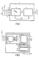
- Figure 1 is an antenna diversity system 1 with n antennas 1-1, 1-2, ..., ii, ..., 1-n, a diversity processor 3 with as many inputs 3-1, 3-2,. .., 3-i, ... 3-n, a downstream FM tuner with IF part 2 and an IF feedback 4 in the diversity processor 3.
- the diversity processor 3 contains a distortion detector 8, as described, for example, in German Offenlegungsschrift 33 26 062 (& EP-A-0132752) or in the unpublished EP-A-0141218, which detects a frequency sweep threshold or additionally when it is detected a disturbance in the IF signal which exceeds an amplitude threshold, outputs a binary signal to a control circuit 9 via a line 11.
- this binary signal will cause the radio-frequency signal fed to the FM tuner with IF part 2 via line 5 to be generated in a different way from the antenna signals of antennas 1-1, ..., 1 -n is derived. Due to the short detection time of the diversity processor 3 for the presence of a disturbance, a corresponding number of signal combinations that can be derived from the antenna signals can be checked for their signal quality in a short time. This ensures that such a signal appears at any point in time when at least one undisturbed combination signal exists by selection at terminal 20.
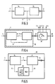
- the diversity processor 3 is equipped with an antenna combiner 10 and an evaluation circuit 30.
- the task of antenna combiner 10 is to form a series of m linear combinations from the n antenna antennas supplied for antennas 1-1,..., 1-n and to switch one of these linear combinations through to the FM tuner with IF part 2. If a malfunction occurs according to a malfunction criterion in the evaluation circuit 30, the antenna combiner 10 is set up in such a way that another linear combination is switched through to the FM tuner with IF part 2 when the evaluation circuit 30 is activated.
- a matrix circuit 18 and a signal selector 19 are contained in the antenna combiner 10, the matrix circuit combining the n antenna signals to form m linear combinations of these signals.
- the signal selector 19 connected to the matrix circuit 18 is in the most general case an addressable switch which, when activated with an address signal emitted by the evaluation circuit 30 on the line 12, connects a specific signal input 19-1,... 19-m to the output 20.
- a binary configuration of the address signal on line 12 is particularly advantageous.
- the evaluation circuit 30 is formed by a distortion detector 8 and a control circuit 9.
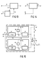
- the distortion detector 8 either consists, for example, of a broadband FM demodulator 32 (FIG. 15) with a downstream first frequency sweep threshold detector 31 with direct signal output (see dashed line) or, if desired, additionally of an AM demodulator (35) with a downstream second threshold detector (36) and an AND circuit (37), both of which are shown in FIG.
- the above-mentioned interference criterion is present when an FM demodulator is used exclusively when a frequency swing disturbance appears in the IF signal of the feedback 4 (FIG. 2), which has a present frequency swing threshold V 1 (FIG. 15) of the suitably set frequency swing threshold detector (31) a comparator circuit is formed.
- the circuit 51 is thus a frequency interference stroke indicator.
- the said interference criterion is given if both there is an amplitude drop that exceeds a suitably set amplitude threshold V2 of the AM threshold detector (36), which is also formed by a comparator circuit, than also a frequency swing disorder appears, which exceeds the above-mentioned frequency swing threshold V1 of the frequency swing threshold detector (31).
- the signal inputs 19-1, ..., 19-m on the signal selector 19 according to a specific priority list stored in the ⁇ -processor of the control circuit 9 with the input 20 of the FM tuner with IF part 2 when the Fault criterion connected.
- 9 address signals 12 are generated in the control circuit.
- Such a list of priorities is determined on the basis of previous reception measurements on the vehicle and the determination of the efficiency of the various linear combinations of the antenna signals and is implemented in the control circuit 9 of the diversity processor 3.
- the signal inputs 19-1, ..., 19-m are assigned the same priority and the signal inputs 19-1, ..., 19-m are cycled with the FM tuner with IF when the interference criterion occurs - Part 2 connected.
- the matrix circuit 18 is generally provided with n antenna inputs 3-1, ..., 3-n and the signal selector 19 with m signal inputs 19-1, ..., 19-n.
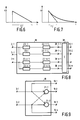
- a subsequent summing circuit 38 certain signals are input to the inputs 38-1-1, ..., 38-1-j; ...; 38-n-1, ..., 38-nk) by summing together to form m signals at outputs 19-1, ..., 19-m connected. It is essential for a good effect that the selector input signals (19-1, ..., 19-m) formed from linear combinations of the antenna signals are statistically as independent as possible from one another. Linear combinations are formed by weighting each antenna signal in amplitude and changing its phase with the aid of a phase shifter (22-1, ..., 22-n) (FIG. 8) and combining all signals.
- these amplitude weighting elements (23-1, ..., 23-n) can be implemented as simple connections.
- the phase rotators (22-1-1, ..., 22-1-j; ...; 22-n-1, ..., 22-nk) are set empirically such that if several antenna signals are disturbed, the probability of the combined signal is as free from interference as possible.
- the number n of antennas that can be used on a vehicle is limited to a low number. In this case, it is advisable to select the number m of the selector inputs (19-1, ... 19-m) larger than the number n of the antennas.
- m n can also be and the matrix circuit 18 connects the inputs 3-1, ..., 3-n with the corresponding outputs 19-1, ..., 19-n directly. It is particularly advantageous to create four signals at inputs (19-1, ..., 19-4) of signal selector 19, the signals of which are formed from two antenna input signals at inputs 3-1, 3-2. This is done, for example, as shown in FIG. 9, by adding the sum and difference of the two antenna input signals in summing and difference circuits 21-1, 21-2 in which the sum signal and the difference signal are fed to the signal inputs 19-2 and 19-3 and in which the separate feeding of the antenna input signals another two signal inputs 19-1, 19-4 from signal selector 19.
- FIG. 10 shows the exemplary application of this principle with three antenna input signals 3-1, 3-2, 3-3, from which new input signals for the signal selector inputs 19-1, ..., 19-9 are formed.
- FIG. 15 shows the basic structure of an exemplary embodiment of the distortion detector 8. In this case, both the frequency interference stroke and the interference-related amplitude modulation in the intermediate-frequency or high-frequency signal 4 are evaluated.
- the interference of the signal 4 is determined exclusively from the frequency interference stroke.
- the frequency interference stroke indicator 51 consists, for example, of a frequency demodulator 32, the output signal 27 of which is fed to the frequency swing threshold detector 31.
- the frequency sweep threshold detector 31 is supplied.
- the frequency deviation threshold detector 31 is implemented as a comparator circuit. If the current frequency swing exceeds a correspondingly predetermined threshold V1, the output signal of the frequency swing threshold detector 31 shows in binary form the presence of a disturbance in the frequency swing.
- the frequency demodulator 32 thus forms one in conjunction with the frequency sweep threshold detector 31
- Frequency interference hub indicator 51 the display of which depends on the setting of the threshold V1 formed in it, which is set greater than the current frequency network hub.
- the interference-related amplitude modulation of the frequency-modulated signal 4 is additionally obtained in the interference amplitude modulation indicator 52 in FIG.
- the output signal of the comparator 36 thus indicates in binary form the presence of an amplitude disturbance.
- a particularly reliable and rapid display of a fault is ensured if the simultaneous presence of a frequency swing and amplitude fault is determined with the aid of an AND circuit 37 using the binary output signal 11 of the AND circuit 37. So if there are interference indications at the output of the frequency interference stroke indicator 51 and at the interference amplitude modulation indicator 52 at the same time, a disturbance of the intermediate-frequency or high-frequency signal 4 is indicated in the output of the AND circuit 37 in the logic signal 11.
- the frequency deviation threshold V 1 or the amplitude threshold V 2 in the distortion detector 8 is fixed to an average value suitable for a large number of reception cases.
- the interference criterion for the FM interference exists when the frequency swing threshold V 1 is exceeded by the frequency swing in the intermediate-frequency or high-frequency signal at point 27, or in the case of simultaneous use of an amplitude demodulator 35, the amplitude threshold V 2 is also exceeded if there is an amplitude dip at point 28. It is known that the interference that can be heard with a system with an antenna is very strongly dependent on the current reception situation, has a very different character and varies greatly over time. With fixed thresholds for fault detection, the faults are recognized very quickly, but the frequency of switching in the signal selector 19 then depends very much on the size and type of the faults.
- the system switches between the too often Selector inputs 19-1, ..., 19-n um and in the presence of relatively small but still audible faults, the system does not switch on.
- the system is not able to always switch the currently best signal to the FM tuner with IF part 2 from the range of selector input signals. It is therefore particularly advantageous to dynamically adapt the thresholds to the average degree of interference. This interference level results from the extent of the amplitude fading, the multi-path reception with large transit time differences, intermodulation interference and adjacent channel interference in the case of a lack of selectivity of the FM tuner with IF part 2. It is very advantageous to raise the thresholds with increasing average interference level.
- the system tracks the signal of the signals present at the input of the signal selector 19 to the FM tuner through the dynamic tracking of the thresholds with IF part 2 which has the smallest disturbance during the search process.
- the degree of interference can be determined in a manner known per se and the thresholds can be controlled accordingly.
- the thresholds are controlled in a particularly advantageous manner in accordance with the signal properties of the high-frequency or intermediate-frequency signal 4.
- the frequency-lifting properties of this signal 4 are present as signal 27 at the output of the frequency demodulator 32.
- the frequency deviation threshold V1 is obtained from the output signal 27 of the frequency demodulator 32 with the aid of a frequency threshold control device 40.
- FIG. 11 describes an advantageous embodiment of the frequency threshold control device 40.
- the dynamically tracked threshold V1 is formed from 3 partial signals.
- One of the 3 sub-signals is derived from the noise signal ratio. This is done with the aid of the N / S circuit 42, which is formed from a high-pass filter with a rectifier connected downstream with a discharge time constant.
- the output signal 48 of the mean value circuit 42 is superimposed on the other partial signals in the summing circuit 44.
- one of the partial signals from signal 27 is obtained with the aid of a frequency useful stroke meter 43, consisting of a low-pass filter with a downstream first rectifier and first integrator.
- a frequency useful stroke meter 43 consisting of a low-pass filter with a downstream first rectifier and first integrator.
- a further partial signal in the form of the signal 17 is obtained from the control circuit 9 in FIG. 5 with the aid of an alternating frequency detector 16, consisting of a rectifier circuit with an integrator, from the binary switching signals 13.
- a particularly favorable dynamic control of the frequency swing threshold V1 is achieved by suitable weighting of the partial signals superimposed in the summing circuit 44. This weighting is to be carried out in such a way that, on the one hand, the sensitivity of the fault display is sufficiently high and, on the other hand, a false indication due to the frequency useful stroke is excluded.
- the simultaneous use of the amplitude modulator with a dynamic amplitude modulation threshold V2 is particularly advantageous for the detection of the presence of the reception disturbances mentioned at the beginning.
- the amplitude disturbance is characterized by short-term drops in amplitude in signal 4.
- the depth of the drop in amplitude is indicated in signal 4.
- the depth of the drop in amplitude is a measure of the extent of the disturbance.
- the voltage at the output of the amplitude demodulator consists in the case of a fault-free DC voltage, the size of which corresponds to the amplitude of the signal 4, and has corresponding drops in the event of a fault. In order to be able to assess the extent of the present fault, the dips in the DC voltage must be measured.
- the amplitude modulation threshold V2 is correspondingly raised as the signal-to-noise ratio becomes smaller in an advantageous development of the invention.
- This noise is found in the output signal 28 of the AM demodulator 35.
- the evaluation of the noise-signal ratio (N / S) takes place in circuit 45 and is superimposed on signal 25 as DC voltage 24 in summing circuit 47.
- the DC voltage 24 is obtained, for example, with the aid of a high-pass filter and a downstream rectifier with a low-pass filter with a cutoff frequency that is preferably below the lowest hearing frequency.
- the limit frequency of the high pass is chosen so high that it does not detect the amplitude fluctuations (vehicle movement) which do not lead to interference.
- the integration of the signal-to-noise ratio (N / S), as described, is preferably carried out with the temporal averaging circuits shown in FIGS. 11 and 12 in the form of the low-pass filters downstream of the rectifiers for the formation of the signals on line 48 or line 24. This is done, for example, in a known manner with the aid of a capacitance.
- These circuits 44 and 45 offer the possibility of appropriately raising the switching thresholds in poor reception situations with relatively large mean values of the disturbance and thus reducing the switching frequency. Excessive switching frequency is always associated with restlessness of the system and circuit-related residual faults.
- the switching frequency can be set in such a way that a more favorable one in the different supply areas dynamic sequence of the search for an undisturbed signal is effected.
- the discharge process is carried out in a manner known per se by connecting an ohmic resistor in parallel with the capacitance.
- the switching frequency mentioned above can be selected appropriately. It is particularly advantageous here if the discharge time constant is chosen to be significantly greater than the minimally occurring activation time of an antenna signal.
- this activation time is limited to the test time of the detector including the runtime caused by the FM receiver with IF part 2.
- the group delay of the FM receiver with IF part 2 is generally limited by its IF bandwidth and is approximately 20 ⁇ s.
- the entirety of the disturbances is obtained with the aid of the distortion detector 8 in the form of a binary signal and is used in a suitable manner, as described below, to raise the threshold V 1 or V 2.
- the use of the binary signal sequence present on the output of the distortion detector 8 on the line 11, which are passed on to the control circuit 9, is suitable. The greater the frequency of the pulses which, as already described, arise in the control circuit 9 and which indicate the presence of a disturbance, the worse the current received signal quality and the greater the total of the disturbances.
- either the frequency of the occurrence of a disturbance is obtained from the binary signal on line 11, which the distortion detector 8 passes on to the control circuit 9, or derived from the address signal on line 12, and as a binary switching signal on line 13 returned to the distortion detector 8 and used as a signal on line 17 in Figure 11 or 12 to raise the threshold voltage V1 or V2.
- An embodiment shows Figure 5 where the frequency of occurrence of a disturbance from pulse signals is obtained by an alternating frequency detector 16, for example a rectifier with a downstream low-pass filter, and from line 17 the distortion detector for raising V1 or V2 is fed. The reshaped and integrated pulses are directly superimposed on the current threshold voltage. This applies to both the amplitude threshold V2 and the frequency swing threshold V1.
- the pulses in the frequency-of-change detector 16 can be converted into a ramp function, as shown in FIG. 6, and subsequently integrated.
- the time t2 of the ramp is suitably set in such a way that a suitable switching frequency is set as a function of the average reception quality.
- an exponential function is used by charging a capacitor for integration and simultaneous discharge via an ohmic resistor connected in parallel.
- the discharge time constant t3 in FIG. 7 can be suitably selected by choosing a suitable product of capacitance and resistance.
- the disturbances generated by the system's ongoing search for a signal worth receiving are thus limited to a tolerable value.
- the frequency interference peaks of all signals are so large that they exceed the respective thresholds V1 or V2.
- the cheapest signal is selected at the input of the signal selector 19.
- Another advantageous exemplary embodiment ascertains the switching frequency of the signal selector 19. Each time the signal selector 19 is switched on, the IF signal on line 4 arises at the different signal inputs 19-1,... 19-m, due to the always different instantaneous values of the carrier amplitude of the signal selector 19, an amplitude jump.
- an amplitude modulation-sensitive FM modulator for example a ratio detector, is used for the purpose of generating pulses at the time of switching, which outputs output pulses in the event of jumps in amplitude.
- FM demodulators are known in radio reception technology and have this property if, as usual, the demodulator is not exactly matched to the center frequency. These pulses are averaged over time in a manner known per se and the current one Average is used to raise the thresholds.
- the switching frequency is adapted to the present signal-to-noise ratio S / N.
- the ratio of noise content to signal content N / S is determined.
- the average signal-to-noise ratio N / S is obtained with the aid of the N / S circuit 42. This consists of a high-pass circuit, the cut-off frequency of which is preferably above the highest occurring frequency of the useful modulation signal, and a downstream rectifier circuit with averaging, which is carried out with the aid of a downstream integrator.
- the average signal-to-noise ratio of the signals at the signal inputs 19-1, ..., 19-m of the signal selector 19 is determined by the N / S circuit 42 during the activation time.
- the activation time is the time within which the system does not advance and the instantaneous signal-to-noise ratio is therefore smaller than the instantaneous value of a set switching threshold.
- the discharge time constant of the integrator in the frequency useful stroke meter 43 is made dependent on the type of modulation. For example, it is set to be relatively short for voice broadcasts and relatively long for music broadcasts. If a music-speech detector is used, the modulation stroke peaks, which are generally larger in the case of speech transmissions, can be taken into account and a better ratio between switching frequency and signal quality can be achieved.
- the modulation frequency useful stroke is measured in a known manner, as in FIG. 11, with the frequency useful stroke meter 43 and the discharge time constant is correspondingly shortened with increasing frequency useful stroke peaks.
- the discharge time constant can be set in a manner known per se with the aid of an electronically adjustable resistor and a constant capacitor.
- a further embodiment provides for a suitable increase in the frequency sweep threshold as a function of the frequency of the frequency interference sweep peaks.
- Antenna diversity system 1 is the simultaneous evaluation of the interference-related frequency swing peaks and the simultaneous interference-related amplitude drops in the high-frequency or intermediate-frequency carrier.
- An amplitude dip is associated with the occurrence of frequency interference peaks.
- the extent of the current degree of amplitude modulation, which occurs simultaneously with a frequency interference spike, is measured at the amplitude threshold V2 ( Figure 15). If the drop is greater than the threshold and there is a frequency interference spike at the same time, then it is certain that the received signal is disturbed at the moment and the system should search for another signal at the input of the signal selector 19.
- the dynamic setting of the amplitude threshold as a function of the signal properties is particularly advantageous here.
- the average value of the carrier amplitude at the output of the circuit 46 provides a favorable criterion for setting the amplitude threshold. As the mean carrier amplitude becomes smaller, the mean signal quality becomes smaller and maintaining the switching thresholds would lead to an unsuitably large switching frequency. To avoid this disadvantage, the average carrier amplitude of circuit 46 is determined and used in the summation circuit 47 for setting the switching threshold V2.
- the energy content of the frequency interference peaks is also used to evaluate the frequency interference.
- the disadvantage of the naturally occurring retardation of the dynamic threshold entrainment is avoided.
- the signal after the FM demodulator 32 and the AM demodulator 35 is suitably delayed by a certain runtime such that e.g. when a large useful modulation stroke peak occurs and a subsequent comparison with the current threshold level V 1, this already has a value adapted to the large useful modulation stroke peak.
- the transit time is selected so that it approximately corresponds to the transit time of the signal path between the FM demodulator output 27 and the input of the threshold value detector, where the comparison with the signal takes place.
- the mute circuit 33 is a "mute" circuit of common knowledge. Either blanking of the low-frequency signal on line 29 (FIG. 13) of the LF part of the FM receiver, not shown, or, in order to avoid switching noises, the instantaneous voltage of this LF signal for the time of the muting 33 be held to continue with the further signal after this time.
- the LF signal is evaluated with the mean value of the output signal at the output 48 of the N / S circuit 42 present signal-to-noise ratio. As the signal-to-noise ratio becomes smaller, it is advantageous to correspondingly reduce the LF signal on line 29 (FIG. 14) with the aid of a potentiometer 34, as a result of which residual disturbances are assessed as less physiologically disturbing.
Landscapes
- Engineering & Computer Science (AREA)
- Computer Networks & Wireless Communication (AREA)
- Signal Processing (AREA)
- Radio Transmission System (AREA)
- Noise Elimination (AREA)
- Variable-Direction Aerials And Aerial Arrays (AREA)
- Digital Transmission Methods That Use Modulated Carrier Waves (AREA)
Claims (14)
- Dispositif à diversité d'antenne pour la réception mobile d'oscillations modulée en fréquence comprenant un récepteur (2), au moins deux antennes 1-i(i=1,2, ... n) et un processeur de diversité (3) auquel est appliqué en retour un signal qui correspond à une certaine combinaison linéaire dérivée des signaux d'antenne, ce processeur de diversité contenant des moyens pour vérifier le signal obtenu en retour et pour éventuellement appliquer au récepteur une autre combinaison linéaire dérivée des signaux d'antenne, caractérisé en ce que le dispositif comprend un tuner FM à section FI (2), que le processeur de diversité (3) reçoit en retour un signal à fréquence intermédiaire ou à haute fréquence qui correspond à une certaine combinaison linéaire dérivée des signaux d'antenne et que le processeur de diversité (3) comprend un démodulateur AM (35) auquel est connecté un détecteur de seuil d'amplitude (36), un démodulateur FM (32) auquel est connecté un détecteur de seuil de déviation de fréquence (31) et des moyens pour, lors d'une apparition simultanée, dans le signal à fréquence intermédiaire ou à haute fréquence, d'une variation brusque d'amplitude excédant le seuil d'amplitude du détecteur de seuil AM et d'une impulsion de déviation de fréquence due à une perturbation excédant le seuil de déviation de fréquence du détecteur de seuil de déviation de fréquence (31), appliquer du côté de l'entrée au tuner FM à section FI (2) une autre combinaison linéaire dérivée des signaux d'antenne.
- Dispositif à diversité d'antenne suivant la revendication 1, caractérisé en ce que le processeur de diversité (3) comprend un combineur d'antennes (10) comportant au moins deux entrées d'antenne (3-i; i= 1,2, ... n) et une sortie de haute fréquence (20) ainsi qu'un circuit d'évaluation (30), le signal à fréquence intermédiaire ou à haute fréquence étant appliqué au circuit d'évaluation (30) et le circuit d'évaluation (30) contenant le détecteur de seuil de déviation de fréquence (31) et le détecteur de seuil d'amplitude (36) pour, en fonction de l'apparition simultanée d'une impulsion de déviation de fréquence, due à une perturbation, excédant le seuil de déviation de fréquence du détecteur de seuil de déviation de fréquence (31) dans le signal à fréquence intermédiaire et d'une variation brusque d'amplitude excédant le seuil d'amplitude du détecteur de seuil d'amplitude (36), fournir un signal d'adresse (12) au combineur d'antennes (10) qui, en fonction du signal d'adresse (12), transmet l'une des combinaisons linéaires de signaux d'antenne à la sortie de haute fréquence (20).
- Dispositif à diversité d'antenne suivant la revendication 2, caractérisé en ce que le combineur d'antennes (10) contient une matrice (18) à n entrées d'antennes (3-1, ..., 3-n) et m sorties de signaux, qui forme m combinaisons linéaires à partir des n signaux d'antenne et les applique aux m sorties de signaux ainsi qu'un sélecteur de signaux (19) à m entrées de signaux (19-1, ..., 19-m) connectées aux sorties de signaux de la matrice (18), une sortie haute fréquence (20) et une entrée d'adresse (12-1), le sélecteur de signaux (19) transmettant à la sortie à haute fréquence (20) le signal de l'entrée de signal (19-1, ..., 19-m) qui correspond à un mot d'adresse présent à l'entrée d'adresse (12).
- Dispositif à diversité d'antenne suivant la revendication 3, caractérisé en ce que la matrice (18) contient un premier circuit sommateur (38) et chaque entrée d'antenne (3-1, ..., 3-n) est connectée chaque fois par l'intermédiaire d'un élément de rotation de phase (22-1-1, ..., 22-1-j; ...; 22-n-1, ..., 22-n-k où j, ..., k sont des nombres entiers quelconques) dont la phase est réglée de manière appropriée, et par l'intermédiaire d'un élément de pondération d'amplitude (23-1-1, ..., 23-1-j; ...; 23-n-1, ..., 23-n-k, où j, ..., k sont des nombres entiers quelconques) dont le facteur de pondération est réglé de manière appropriée, aux entrées (38-1-1; 38-1-j; ...; 38-n-1, ... 38-n-k) du circuit sommateur (38), et chaque sortie du circuit sommateur (38) est connectée à l'une des entrées de signaux (19-1, ..., 19-m) du sélecteur de signaux (19).
- Dispositif à diversité d'antenne suivant la revendication 4, caractérisé en ce que le nombre n des entrées d'antenne (3-1, ... 3-n) de la matrice (18) et le nombre m des entrées de signaux (19-1, ... 19-m) du sélecteur de signaux (19) sont identiques et chaque entrée d'antenne (3-1, ..., 3-n) est connectée par l'intermédiaire d'un élément de pondération d'amplitude (23) à chaque fois une des m entrées de signaux (19-1, ... 19-m) du sélecteur de signaux (19) et le facteur de pondération est réglé de manière appropriée.
- Dispositif à diversité d'antenne suivant la revendication 5, caractérisé en ce que les éléments de pondération d'amplitude (23) sont réglés de manière telle que les valeurs moyennes temporelles des rapports signal/bruit de l'ensemble des signaux d'entrée de sélecteur (19-1, ..., 19-m) soient aussi semblables que possible.
- Dispositif à diversité d'antenne suivant la revendication 4, caractérisé en ce que le combineur d'antennes (10) comporte deux entrées d'antenne (3-1 et 3-2) ainsi qu'un second circuit sommateur (22-1) et un premier circuit soustracteur (21-2), les entrées d'antenne (3-1, 3-2) étant d'une part connectées toutes deux au circuit sommateur (21-1) et au circuit soustracteur (21-2), le circuit sommateur et le circuit soustracteur étant connectés à une entrée de signaux (19-2, 19-3) du sélecteur de signaux (19) et étant d'autre part chacun connectés directement à une autre entrée de signaux (19-1, 19-4) du sélecteur de signaux (19).
- Dispositif à diversité d'antenne suivant la revendication 3, caractérisé en ce que le circuit d'évaluation (30) comprend un détecteur de distorsion (8) et un circuit de commande (9) et le détecteur de distorsion (8) connecté au tuner FM à section FI (2) fournit un signal logique binaire (11) au circuit de commande (9) en fonction de l'apparition d'une impulsion de déviation de fréquence due à une perturbation excédant le seuil de déviation de fréquence du détecteur de seuil de déviation de fréquence (31) dans le signal de fréquence intermédiaire (4) ou, en outre, d'une variation brusque d'amplitude excédant le seuil d'amplitude du détecteur de seuil d'amplitude (36) et le détecteur de distorsion (8) fournissant, en réponse au signal logique binaire (11), un signal d'adresse (12) approprié à l'entrée d'adresse (12-1) du sélecteur de signaux (19).
- Dispositif à diversité d'antenne suivant la revendication 8, caractérisé en ce que le circuit de commande (9) connecte les entrées de signaux (19-1, ... 19-m) du sélecteur de signaux (19) selon une liste de priorités au tuner FM à section FI (2).
- Dispositif à diversité d'antenne suivant la revendication 1, caractérisé en ce que le processeur de diversité (3) comprend un dispositif de réglage de seuil de déviation de fréquence (40) connecté entre le démodulateur FM (31) et une borne d'entrée (V₁) du détecteur de seuil de déviation de fréquence (31) pour la régulation dynamique du seuil de déviation de fréquence V₁ ou comprend, en outre, un dispositif de réglage de seuil d'amplitude connecté entre le démodulateur AM (35) et une borne d'entrée (V₂) du détecteur de seuil d'amplitude (36) pour la régulation dynamique du seuil d'amplitude (V₂) du détecteur de seuil d'amplitude (36).
- Dispositif à diversité d'antenne suivant la revendication 10, caractérisé en ce que le dispositif de réglage de seuil de déviation de fréquence (40) comprend un filtre passe-haut connecté au troisième circuit sommateur (44) et suivi d'un circuit redresseur et intégrateur N/S (42) ainsi qu'un filtre passe-bas connecté au troisième circuit sommateur (44) et suivi d'un premier redresseur et d'un premier réintégrateur (mesure de déviation utile de fréquence 43) et que le dispositif de réglage de seuil d'amplitude (41) comprend un dispositif de mesure de taux de modulation (46) connecté au deuxième circuit soustracteur (47) et un deuxième redresseur suivi d'un deuxième intégrateur (46) connecté au deuxième circuit soustracteur (47).
- Dispositif à diversité d'antenne suivant la revendication 8, caractérisé en ce que le circuit d'évaluation (30) contient un détecteur de fréquence d'alternance (9, 16) pour régler, en fonction de la fréquence détectée de l'alternance de signaux des combinaisons de signaux d'antenne appliquées au tuner FM à section FI (2) pour régler la fréquence de l'alternance de signaux.
- Dispositif à diversité d'antenne suivant la revendication 12, caractérisé en ce que le détecteur de fréquence d'alternance (9, 16) contient un générateur d'impulsions monté dans le circuit de commande (9) pour générer des impulsions en fonction du signal logique binaire appliqué au circuit de commande (9) ainsi qu'un troisième redresseur suivi d'un troisième intégrateur connecté entre le circuit de commande (9) et le détecteur de distorsion (8) pour régler le seuil de déviation de fréquence (V₁) ou en plus le seuil d'amplitude (V₂).
- Dispositif à diversité d'antenne suivant la revendication 13, caractérisé en ce que le troisième intégrateur est connecté au troisième circuit sommateur (44) ou, en outre, au deuxième circuit soustracteur (47).
Applications Claiming Priority (2)
| Application Number | Priority Date | Filing Date | Title |
|---|---|---|---|
| DE3517247 | 1985-05-13 | ||
| DE19853517247 DE3517247A1 (de) | 1985-05-13 | 1985-05-13 | Antennendiversity-empfangsanlage zur elimination von empfangsstoerungen |
Publications (3)
| Publication Number | Publication Date |
|---|---|
| EP0201977A2 EP0201977A2 (fr) | 1986-11-20 |
| EP0201977A3 EP0201977A3 (en) | 1988-08-24 |
| EP0201977B1 true EP0201977B1 (fr) | 1993-03-03 |
Family
ID=6270635
Family Applications (1)
| Application Number | Title | Priority Date | Filing Date |
|---|---|---|---|
| EP86200803A Expired - Lifetime EP0201977B1 (fr) | 1985-05-13 | 1986-05-07 | Dispositif de réception à diversité d'antenne destiné à éliminer des perturbations de réception |
Country Status (9)
| Country | Link |
|---|---|
| US (1) | US4752968A (fr) |
| EP (1) | EP0201977B1 (fr) |
| JP (1) | JP2530317B2 (fr) |
| KR (1) | KR950001371B1 (fr) |
| CN (1) | CN1007861B (fr) |
| BR (1) | BR8602122A (fr) |
| CA (1) | CA1257339A (fr) |
| DE (2) | DE3517247A1 (fr) |
| ES (1) | ES8801068A1 (fr) |
Cited By (1)
| Publication number | Priority date | Publication date | Assignee | Title |
|---|---|---|---|---|
| DE4403612B4 (de) * | 1994-02-05 | 2008-10-02 | Lindenmeier, Heinz, Prof. Dr. Ing. | Schaltungsanordnung für ein Mehrantennen-Scanning-Diversitysystem für Kraftfahrzeuge |
Families Citing this family (51)
| Publication number | Priority date | Publication date | Assignee | Title |
|---|---|---|---|---|
| DE3641109A1 (de) * | 1986-12-02 | 1988-08-25 | Lindenmeier Heinz | Signaldiversity-anlage fuer den mobilen empfang |
| DE3836046A1 (de) | 1987-10-31 | 1989-05-11 | Hirschmann Radiotechnik | Empfangsverfahren und empfangs-antennensystem zur durchfuehrung des verfahrens |
| DE3736969C1 (de) * | 1987-10-31 | 1989-06-29 | Hirschmann Radiotechnik | Verfahren zur Dimensionierung von Antennen-Empfangssytemen fuer mobilen Empfang |
| DE3802131A1 (de) * | 1988-01-26 | 1989-08-03 | Hirschmann Radiotechnik | Antennensystem fuer den rundfunkempfang in kraftfahrzeugen |
| DE3802130A1 (de) * | 1988-01-26 | 1989-08-03 | Hirschmann Radiotechnik | Antennensystem fuer den rundfunkempfang in kraftfahrzeugen |
| DE3814899A1 (de) | 1988-05-03 | 1989-11-16 | Hirschmann Richard Gmbh Co | Empfangsverfahren und empfangs-antennensystem fuer mobilen empfang |
| DE3824528A1 (de) * | 1988-07-20 | 1990-01-25 | Hirschmann Richard Gmbh Co | Leistungsaddierer |
| WO1990011656A1 (fr) * | 1989-03-28 | 1990-10-04 | Nippon Telegraph And Telephone Corporation | Circuit recepteur en diversite |
| US5261121A (en) * | 1989-08-11 | 1993-11-09 | Nec Corporation | Portable radio transceiver system having improved adaptor and/or improved receiver signal control arrangement |
| DE3932659C1 (en) * | 1989-09-29 | 1991-03-28 | Richard Hirschmann Gmbh & Co, 7300 Esslingen, De | Room e.g. vehicle interior and-or object monitoring method - examining changes in EM field beam from transmitter and activating alarm when amplitude of detected signals exceeds set level |
| DE3942626C1 (fr) * | 1989-12-22 | 1991-01-31 | Richard Hirschmann Gmbh & Co, 7300 Esslingen, De | |
| US5210194A (en) * | 1990-01-25 | 1993-05-11 | Farmitalia Carlo Erba S.R.L. An Italian Body Corporate | Process for preparing ergoline derivatives |
| US5175878A (en) * | 1990-02-02 | 1992-12-29 | At&T Bell Laboratories | Radio network with switching arrangement for coupling radios to a selected antenna out of a plurality of antennas |
| DE4008502A1 (de) * | 1990-03-16 | 1991-09-19 | Hirschmann Richard Gmbh Co | Verfahren zum mobilen empfang von digitalen signalen |
| DE4024178C2 (de) * | 1990-07-30 | 1995-08-17 | Hirschmann Richard Gmbh Co | Verfahren für den mobilen Empfang von frequenzmodulierten Stereo-Multiplexsignalen |
| DE4101629C3 (de) * | 1991-01-21 | 2003-06-26 | Fuba Automotive Gmbh | Antennendiversity-Anlage mit mindestens zwei Antennen für den mobilen Empfang von Meter- und Dezimeterwellen |
| DE4204490B4 (de) * | 1992-02-14 | 2004-04-15 | Heinz Prof. Dr.-Ing. Lindenmeier | Schaltungsanordnung zur Unterdrückung von Umschaltstörungen bei Antennendiversity |
| US5479448A (en) * | 1992-03-31 | 1995-12-26 | At&T Corp. | Method and apparatus for providing antenna diversity |
| DE4303979A1 (de) * | 1993-02-11 | 1994-08-18 | Kolbe & Co Hans | Autoradio mit Antennendiversity |
| DE4324304B4 (de) * | 1993-07-20 | 2005-01-27 | Harman Becker Automotive Systems (Becker Division) Gmbh | Verfahren zur Unterdrückung von Empfangsstörungen in einem FM-Empfänger |
| DE4326843C2 (de) * | 1993-08-10 | 1997-11-20 | Hirschmann Richard Gmbh Co | Empfangsverfahren und Empfangsantennensystem zur Beseitigung von Mehrwegstörungen bzw. Steuergerät zur Durchführung dieses Verfahrens |
| DE4332476A1 (de) * | 1993-09-24 | 1995-03-30 | Bosch Gmbh Robert | Verfahren und Einrichtung zur Übertragung von Datensignalen |
| DE4343959C2 (de) * | 1993-12-22 | 1996-04-25 | Hirschmann Richard Gmbh Co | Empfangsverfahren und Empfangsantennensystem zur Beseitigung von Mehrwegstörungen bzw. Steuergerät zur Durchführung dieses Verfahrens |
| DE4441761A1 (de) | 1994-11-23 | 1996-05-30 | Lindenmeier Heinz | Mehrantennen-Scanning-Diversitysystem für Fahrzeuge |
| DE19858465A1 (de) | 1998-12-17 | 2000-06-21 | Heinz Lindenmeier | Scanning-Diversity-Antennensystem für Fahrzeuge |
| EP1032073A3 (fr) * | 1999-02-26 | 2003-07-09 | Nippon Sheet Glass Co., Ltd. | Système de diversité pour VHF monté sur un véhicule |
| DE19931252C1 (de) * | 1999-07-07 | 2001-03-29 | Bosch Gmbh Robert | Schaltungsanordnung und Verfahren zur Prüfung eines Rundfunkempfangssystems |
| DE19935675A1 (de) * | 1999-07-29 | 2001-02-15 | Bosch Gmbh Robert | Schaltung zum Umschalten zwischen Empfangsantennen |
| US6470192B1 (en) | 1999-08-16 | 2002-10-22 | Telefonaktiebolaget Lm Ericcson (Publ) | Method of an apparatus for beam reduction and combining in a radio communications system |
| EP1592083B1 (fr) * | 2000-01-19 | 2013-04-03 | Fractus, S.A. | antennes miniatures de remplissage d'espace |
| DE10109359C2 (de) * | 2001-02-27 | 2003-01-16 | Bosch Gmbh Robert | Diversity-Antennenanordnung |
| JP2005512389A (ja) * | 2001-12-06 | 2005-04-28 | コーニンクレッカ フィリップス エレクトロニクス エヌ ヴィ | 寄生素子のダイバーシティアンテナ |
| DE10161271A1 (de) * | 2001-12-13 | 2003-07-03 | Harman Becker Automotive Sys | Verfahren zur Auswahl einer von mehreren Antennen einer Antennendiversity-Empfangsanlage und Antennendiversity-Empfangsanlage |
| DE102004006015A1 (de) * | 2004-02-06 | 2005-08-25 | Robert Bosch Gmbh | Verfahren und Vorrichtung zur Anpassung eines Schwellwertes einer Detektionseinrichtung |
| US20090040027A1 (en) * | 2005-04-07 | 2009-02-12 | Nec Corporation | RFID System, Power Supply Device and Power Supply Method |
| US20090051499A1 (en) * | 2005-04-07 | 2009-02-26 | Nec Corporation | RFID System, Reader, Control, Program and Transmission Method |
| DE102006039357B4 (de) * | 2005-09-12 | 2018-06-28 | Heinz Lindenmeier | Antennendiversityanlage zum Funkempfang für Fahrzeuge |
| US8738103B2 (en) | 2006-07-18 | 2014-05-27 | Fractus, S.A. | Multiple-body-configuration multimedia and smartphone multifunction wireless devices |
| US7668525B2 (en) * | 2007-03-01 | 2010-02-23 | Delphi Technologies, Inc. | System and method of a stereo receiving system |
| DE102007017478A1 (de) | 2007-04-13 | 2008-10-16 | Lindenmeier, Heinz, Prof. Dr. Ing. | Empfangsanlage mit einer Schaltungsanordnung zur Unterdrückung von Umschaltstörungen bei Antennendiversity |
| WO2008144879A1 (fr) * | 2007-05-31 | 2008-12-04 | The Governors Of The University Of Alberta | Pré-processeur pour une diversité d'antennes de récepteur |
| EP2037593A3 (fr) * | 2007-07-10 | 2016-10-12 | Delphi Delco Electronics Europe GmbH | Installation de diversité d'antennes pour la réception radio à bande relativement large dans des véhicules |
| DE102007039914A1 (de) * | 2007-08-01 | 2009-02-05 | Lindenmeier, Heinz, Prof. Dr. Ing. | Antennendiversityanlage mit zwei Antennen für den Funkempfang in Fahrzeugen |
| DE102008003532A1 (de) * | 2007-09-06 | 2009-03-12 | Lindenmeier, Heinz, Prof. Dr. Ing. | Antenne für den Satellitenempfang |
| EP2207273B1 (fr) * | 2009-01-09 | 2016-01-06 | AKG Acoustics GmbH | Procédé et dispositif de réception de données audio numériques |
| PT2209221T (pt) * | 2009-01-19 | 2018-12-27 | Fuba Automotive Electronics Gmbh | Sistema de recepção para a soma de sinais de antena em fase |
| DE102009011542A1 (de) * | 2009-03-03 | 2010-09-09 | Heinz Prof. Dr.-Ing. Lindenmeier | Antenne für den Empfang zirkular in einer Drehrichtung der Polarisation ausgestrahlter Satellitenfunksignale |
| DE102009023514A1 (de) * | 2009-05-30 | 2010-12-02 | Heinz Prof. Dr.-Ing. Lindenmeier | Antenne für zirkulare Polarisation mit einer leitenden Grundfläche |
| US8817917B2 (en) | 2011-06-21 | 2014-08-26 | Ibiquity Digital Corporation | Method and apparatus for implementing signal quality metrics and antenna diversity switching control |
| CN111323804B (zh) * | 2020-04-22 | 2023-08-29 | 北京国泰星云科技有限公司 | 一种基于北斗系统的船舶姿态测量设备及测量方法 |
| CN112363188B (zh) * | 2020-10-13 | 2021-06-11 | 无锡卡尔曼导航技术有限公司 | 一种多分集卫星导航接收机跟踪环路方法及装置 |
Family Cites Families (8)
| Publication number | Priority date | Publication date | Assignee | Title |
|---|---|---|---|---|
| US3840875A (en) * | 1973-08-23 | 1974-10-08 | J Neal | Radiant energy matrix and system |
| DE2827572C2 (de) * | 1978-06-23 | 1980-08-28 | Blaupunkt-Werke Gmbh, 3200 Hildesheim | Verfahren zur Störbeseitigung in einer mobilen Rundfunkempfangsanlage |
| US4293955A (en) * | 1980-03-17 | 1981-10-06 | Telex Communications, Inc. | Diversity reception system |
| JPS577643A (en) * | 1980-06-17 | 1982-01-14 | Nec Corp | Multiple-antenna space diversity system |
| DE3326062A1 (de) * | 1983-07-20 | 1985-01-31 | Gerhard Prof. Dr.-Ing. 8012 Ottobrunn Flachenecker | Detektor zur anzeige von frequenzstoerhubspitzen |
| DE3334735A1 (de) * | 1983-09-26 | 1985-04-18 | Gerhard Prof. Dr.-Ing. 8012 Ottobrunn Flachenecker | Detektor zum anzeigen von empfangsstoerungen bei mehrwegeempfang |
| JPS60132430A (ja) * | 1983-12-21 | 1985-07-15 | Toshiba Corp | 妨害波除去装置 |
| JPS60223337A (ja) * | 1984-04-20 | 1985-11-07 | Matsushita Electric Ind Co Ltd | 角度ダイバ−シテイ受信装置 |
-
1985
- 1985-05-13 DE DE19853517247 patent/DE3517247A1/de not_active Ceased
-
1986
- 1986-05-07 DE DE8686200803T patent/DE3687854D1/de not_active Expired - Lifetime
- 1986-05-07 EP EP86200803A patent/EP0201977B1/fr not_active Expired - Lifetime
- 1986-05-08 CA CA000508661A patent/CA1257339A/fr not_active Expired
- 1986-05-08 US US06/861,205 patent/US4752968A/en not_active Expired - Lifetime
- 1986-05-09 ES ES554814A patent/ES8801068A1/es not_active Expired
- 1986-05-10 CN CN86103844A patent/CN1007861B/zh not_active Expired
- 1986-05-12 BR BR8602122A patent/BR8602122A/pt not_active IP Right Cessation
- 1986-05-13 JP JP61107814A patent/JP2530317B2/ja not_active Expired - Lifetime
- 1986-05-13 KR KR1019860003718A patent/KR950001371B1/ko not_active Expired - Lifetime
Cited By (1)
| Publication number | Priority date | Publication date | Assignee | Title |
|---|---|---|---|---|
| DE4403612B4 (de) * | 1994-02-05 | 2008-10-02 | Lindenmeier, Heinz, Prof. Dr. Ing. | Schaltungsanordnung für ein Mehrantennen-Scanning-Diversitysystem für Kraftfahrzeuge |
Also Published As
| Publication number | Publication date |
|---|---|
| DE3517247A1 (de) | 1986-11-13 |
| CN1007861B (zh) | 1990-05-02 |
| CA1257339A (fr) | 1989-07-11 |
| BR8602122A (pt) | 1987-01-13 |
| CN86103844A (zh) | 1987-08-19 |
| JP2530317B2 (ja) | 1996-09-04 |
| US4752968A (en) | 1988-06-21 |
| JPS6230430A (ja) | 1987-02-09 |
| KR950001371B1 (ko) | 1995-02-17 |
| KR860009599A (ko) | 1986-12-23 |
| ES8801068A1 (es) | 1987-12-01 |
| EP0201977A2 (fr) | 1986-11-20 |
| ES554814A0 (es) | 1987-12-01 |
| EP0201977A3 (en) | 1988-08-24 |
| DE3687854D1 (de) | 1993-04-08 |
Similar Documents
| Publication | Publication Date | Title |
|---|---|---|
| EP0201977B1 (fr) | Dispositif de réception à diversité d'antenne destiné à éliminer des perturbations de réception | |
| DE2558557C3 (de) | Mehifach-Empfangssystem | |
| DE3131292C2 (fr) | ||
| EP1455466A1 (fr) | Système de scanning diversifié à multiples antennes pour la fréquence FM pour des véhicules | |
| EP1021000B1 (fr) | Système d'antennes de balayage en diversité pour véhicules | |
| DE4111847A1 (de) | Diversity-empfaenger | |
| DE3130864C2 (de) | Rundfunkempfänger | |
| EP0829973A2 (fr) | Dispositif avec diversité de fréquence pour la réception mobile de télévision | |
| DE3926336C2 (de) | Antennendiversity-Empfangsanlage zur Elimination von Empfangsstörungen beim mobilen Empfang von Fernsehsignalen | |
| EP0998058B1 (fr) | Système de selection d'antennes à balayage pour véhicules | |
| EP0270188B1 (fr) | Installation de diversité de signal pour la réception mobile | |
| DE3828817A1 (de) | Raumdiversity-empfaengerschaltung | |
| DE4403612B4 (de) | Schaltungsanordnung für ein Mehrantennen-Scanning-Diversitysystem für Kraftfahrzeuge | |
| DE69528934T2 (de) | FM-Empfänger | |
| EP1366580A1 (fr) | Systeme d'antennes diversifie | |
| DE3721918C1 (en) | Method for evaluating the suitability for reception of the frequency-modulated broadcast transmissions received in an FM broadcast receiver, and circuit arrangement for carrying out the method | |
| DE10131457A1 (de) | Antennenanschlußanordnung, Antennensignalsplitter und Verfahren zur Empfangsfrequenzsteuerung | |
| DE2519055A1 (de) | Fm-empfaenger | |
| EP0069214B1 (fr) | Circuit pour déterminer la qualité de réception d'un récepteur FM | |
| DE19533268A1 (de) | Verfahren zum Betreiben eines Rundfunkempfängers | |
| DE10130234A1 (de) | Funkempfangssystem | |
| EP1271816B1 (fr) | Procédé de recherche d'une fréquence dans un récepteur radio | |
| DE19722385C2 (de) | Verfahren zur Erkennung von Multipathstörungen beim FM-Rundfunkempfang und Schaltungsanordnung zur Durchführung des Verfahrens | |
| EP1098453B1 (fr) | Procédé pour sélectionner une antenne parmi une pluralité d'antennes dans une installation de réception en diversité d'antennes et installation de réception en diversité d'antennes | |
| EP0428866B1 (fr) | Procédé et dispositif pour supprimer les changements d'émetteur dans des récepteurs avec RDS dûs à des perturbations locales |
Legal Events
| Date | Code | Title | Description |
|---|---|---|---|
| PUAI | Public reference made under article 153(3) epc to a published international application that has entered the european phase |
Free format text: ORIGINAL CODE: 0009012 |
|
| AK | Designated contracting states |
Kind code of ref document: A2 Designated state(s): DE FR GB IT NL SE |
|
| PUAL | Search report despatched |
Free format text: ORIGINAL CODE: 0009013 |
|
| AK | Designated contracting states |
Kind code of ref document: A3 Designated state(s): DE FR GB IT NL SE |
|
| 17P | Request for examination filed |
Effective date: 19890227 |
|
| D17P | Request for examination filed (deleted) | ||
| 17Q | First examination report despatched |
Effective date: 19910320 |
|
| GRAA | (expected) grant |
Free format text: ORIGINAL CODE: 0009210 |
|
| AK | Designated contracting states |
Kind code of ref document: B1 Designated state(s): DE FR GB IT NL SE |
|
| REF | Corresponds to: |
Ref document number: 3687854 Country of ref document: DE Date of ref document: 19930408 |
|
| ITF | It: translation for a ep patent filed | ||
| RAP2 | Party data changed (patent owner data changed or rights of a patent transferred) |
Owner name: FUBA HANS KOLBE & CO Owner name: N.V. PHILIPS' GLOEILAMPENFABRIEKEN |
|
| GBT | Gb: translation of ep patent filed (gb section 77(6)(a)/1977) |
Effective date: 19930526 |
|
| ET | Fr: translation filed | ||
| NLT2 | Nl: modifications (of names), taken from the european patent patent bulletin |
Owner name: N.V. PHILIPS' GLOEILAMPENFABRIEKEN TE EINDHOVEN EN |
|
| PLBE | No opposition filed within time limit |
Free format text: ORIGINAL CODE: 0009261 |
|
| STAA | Information on the status of an ep patent application or granted ep patent |
Free format text: STATUS: NO OPPOSITION FILED WITHIN TIME LIMIT |
|
| 26N | No opposition filed | ||
| ITTA | It: last paid annual fee | ||
| EAL | Se: european patent in force in sweden |
Ref document number: 86200803.4 |
|
| ITPR | It: changes in ownership of a european patent |
Owner name: CAMBIO RAGIONE SOCIALE;PHILIPS ELECTRONICS N.V. |
|
| REG | Reference to a national code |
Ref country code: FR Ref legal event code: CD |
|
| NLT1 | Nl: modifications of names registered in virtue of documents presented to the patent office pursuant to art. 16 a, paragraph 1 |
Owner name: PHILIPS ELECTRONICS N.V. |
|
| REG | Reference to a national code |
Ref country code: GB Ref legal event code: 732E |
|
| REG | Reference to a national code |
Ref country code: FR Ref legal event code: TP |
|
| PGFP | Annual fee paid to national office [announced via postgrant information from national office to epo] |
Ref country code: NL Payment date: 19970531 Year of fee payment: 12 |
|
| NLS | Nl: assignments of ep-patents |
Owner name: PHILIPS ELECTRONICS N.V.;FUBA AUTOMOTIVE GMBH |
|
| NLT1 | Nl: modifications of names registered in virtue of documents presented to the patent office pursuant to art. 16 a, paragraph 1 |
Owner name: HANS KOLBE & CO.;PHILIPS ELECTRONICS N.V. |
|
| PGFP | Annual fee paid to national office [announced via postgrant information from national office to epo] |
Ref country code: FR Payment date: 19980529 Year of fee payment: 13 |
|
| REG | Reference to a national code |
Ref country code: FR Ref legal event code: TP |
|
| REG | Reference to a national code |
Ref country code: GB Ref legal event code: 732E |
|
| PG25 | Lapsed in a contracting state [announced via postgrant information from national office to epo] |
Ref country code: NL Free format text: LAPSE BECAUSE OF NON-PAYMENT OF DUE FEES Effective date: 19981201 |
|
| NLV4 | Nl: lapsed or anulled due to non-payment of the annual fee |
Effective date: 19981201 |
|
| GBPC | Gb: european patent ceased through non-payment of renewal fee |
Effective date: 19990507 |
|
| PG25 | Lapsed in a contracting state [announced via postgrant information from national office to epo] |
Ref country code: FR Free format text: LAPSE BECAUSE OF NON-PAYMENT OF DUE FEES Effective date: 20000131 |
|
| REG | Reference to a national code |
Ref country code: FR Ref legal event code: ST |
|
| REG | Reference to a national code |
Ref country code: GB Ref legal event code: 728V |
|
| REG | Reference to a national code |
Ref country code: GB Ref legal event code: 728Y |
|
| PGFP | Annual fee paid to national office [announced via postgrant information from national office to epo] |
Ref country code: GB Payment date: 20040505 Year of fee payment: 19 |
|
| PGFP | Annual fee paid to national office [announced via postgrant information from national office to epo] |
Ref country code: SE Payment date: 20040506 Year of fee payment: 19 |
|
| PGFP | Annual fee paid to national office [announced via postgrant information from national office to epo] |
Ref country code: DE Payment date: 20050506 Year of fee payment: 20 |
|
| PG25 | Lapsed in a contracting state [announced via postgrant information from national office to epo] |
Ref country code: GB Free format text: LAPSE BECAUSE OF NON-PAYMENT OF DUE FEES Effective date: 20050507 |
|
| PG25 | Lapsed in a contracting state [announced via postgrant information from national office to epo] |
Ref country code: SE Free format text: LAPSE BECAUSE OF NON-PAYMENT OF DUE FEES Effective date: 20050508 |
|
| PGFP | Annual fee paid to national office [announced via postgrant information from national office to epo] |
Ref country code: IT Payment date: 20050531 Year of fee payment: 20 |
|
| EUG | Se: european patent has lapsed | ||
| GBPC | Gb: european patent ceased through non-payment of renewal fee |
Effective date: 20050507 |