EP0998980A1 - Désintégrateur à arbres parallèles entraínés par moteur - Google Patents
Désintégrateur à arbres parallèles entraínés par moteur Download PDFInfo
- Publication number
- EP0998980A1 EP0998980A1 EP99120794A EP99120794A EP0998980A1 EP 0998980 A1 EP0998980 A1 EP 0998980A1 EP 99120794 A EP99120794 A EP 99120794A EP 99120794 A EP99120794 A EP 99120794A EP 0998980 A1 EP0998980 A1 EP 0998980A1
- Authority
- EP
- European Patent Office
- Prior art keywords
- arms
- shredding
- shafts
- crushing
- shaft
- Prior art date
- Legal status (The legal status is an assumption and is not a legal conclusion. Google has not performed a legal analysis and makes no representation as to the accuracy of the status listed.)
- Granted
Links
Images




Classifications
-
- B—PERFORMING OPERATIONS; TRANSPORTING
- B02—CRUSHING, PULVERISING, OR DISINTEGRATING; PREPARATORY TREATMENT OF GRAIN FOR MILLING
- B02C—CRUSHING, PULVERISING, OR DISINTEGRATING IN GENERAL; MILLING GRAIN
- B02C18/00—Disintegrating by knives or other cutting or tearing members which chop material into fragments
- B02C18/06—Disintegrating by knives or other cutting or tearing members which chop material into fragments with rotating knives
- B02C18/14—Disintegrating by knives or other cutting or tearing members which chop material into fragments with rotating knives within horizontal containers
- B02C18/142—Disintegrating by knives or other cutting or tearing members which chop material into fragments with rotating knives within horizontal containers with two or more inter-engaging rotatable cutter assemblies
-
- B—PERFORMING OPERATIONS; TRANSPORTING
- B02—CRUSHING, PULVERISING, OR DISINTEGRATING; PREPARATORY TREATMENT OF GRAIN FOR MILLING
- B02C—CRUSHING, PULVERISING, OR DISINTEGRATING IN GENERAL; MILLING GRAIN
- B02C18/00—Disintegrating by knives or other cutting or tearing members which chop material into fragments
- B02C18/06—Disintegrating by knives or other cutting or tearing members which chop material into fragments with rotating knives
- B02C18/16—Details
- B02C18/18—Knives; Mountings thereof
Definitions
- the invention relates to a shredding device with two essentially parallel, motor-driven Waves arranged in the bottom area of a feed hopper are, according to the preamble of claim 1.
- Double-shaft shredders with mechanical acting tearing and clearing elements belong to the known State of the art.
- the shredding device shown there has a funnel-like container in which Outlet area two crusher rollers parallel to each other are that can be driven in opposite directions.
- the crushing rollers of such crushing devices are constructed in different ways, always with the basic principle it lies on the outer circumference of the crusher rollers Form elements, these elements interlocking. In this way, the material that gets between the rollers of the elements located on the rollers and taken to Roll gap transported and shredded.
- the Crusher roller has a cylindrical body which several, spaced apart disc elements are attached, in turn several at their peripheral area Crusher elements are attached.
- the breaker elements are supposed to with respect to the longitudinal axis of the crusher shafts against each other be arranged offset so that the crusher elements each in opposite spaces between adjacent crusher rollers intervene to clear the spaces between crushed particles clean, i.e. to clear out.
- the known Crusher element should be plate-shaped and essentially arranged in a tangential plane of the disk element become.
- Crusher element can absorb the appropriate forces according to known utility model highlighted that it is necessary is to provide additional support elements or support bodies.
- the Support bodies are the with respect to the working direction Arrange crusher roller in front of the crusher element. By a cutting-like shape of the support body should this also improve the crushing.
- the individual crusher elements adjacent discs preferably in the circumferential direction staggered, so that in a side view Crusher roller a spiral formation of each Sets crusher elements.
- the crusher rollers are can be driven in both directions of rotation in a preferred manner. With regard to the nip formed by the crusher rollers the rollers move towards each other in the working direction emotional. In the case when a workpiece or to be shredded Is well jammed between or by the rollers on one Reversed direction of rotation in order to avoid the nip to work freely.
- the basic idea of the invention is accordingly one of known double shaft shredding device to go out, however, to shredding in both directions of rotation Waves fall back, so even in the case when one middle shredding area, namely the one between the Clogged rollers or there is such a risk of clogging, the shredding process in the side, adjacent to the rollers Areas continued or taken over by these areas becomes.
- the disk-shaped tool carrier Device designed so that it extends radially Have arms with recesses in between.
- Anne with setbacks is the actual recording area, who grasped the abandoned good, very large, so that each amount of material to be shredded can be optimized can.
- a front and back tear wear insert extending in the shaft rotation direction as well as extending in the shaft longitudinal direction and between the front and back tear wear insert are arranged the mentioned clearers.
- the arms of the tool carriers fastened on the shafts engage in the intermediate shaft area, so that an optimal transmission of force to the material to be shredded is ensured.
- the feed hopper which is designed in a manner known per se, according to the invention, in the area of the plane spanned by the shaft axes, on both sides of the shafts which have the tool carriers, these are adjacent and immersed in the tool carrier spacing, special removal and crushing tines.
- the tool carrier and the side clearing and crushing tines now result in further crushing zones, on both sides adjacent to the shafts, so that even with a reversing shaft drive, the desired crushing of the material is achieved by the interaction between the crushing tines on the one hand and the rotating tools on the tool carrier on the other sets.
- the tines thus take on a partial function in terms of crushing, breaking and tearing, but also a clearing function in interaction with the clearers located on the arms.
- the disc-shaped Tool carriers preferably four, the same on the circumference spaced arms in place, along the shafts fixed tool carrier with arms a spiral offset own and the scraper attached to the outer arm end extend on both sides of the tool carrier or arm.
- discharged Material can vary the number of arms of the tool carrier are preferred, with a variance in the range of two to eight being preferred is.
- the clearers which are attached to the arms, have a width such that the interlocking arms of the an adjacent tool carrier attached to the shafts defined clearing distance or at least partially Overlapping adjacent clearers result. Also through this Measure is a universal adaptation of the shredding device to the type of material and thus to the Operational tasks guaranteed.
- the Arms of different length i.e. a different radial expansion, so that an internal and an outer circle with different peripheral speeds sets. Because of these different peripheral speeds at the outer end of the arm where the actual Active elements with respect to the crushing process overall, the tear behavior is improved.
- the clearing and crushing tines in the hopper are in the essentially parallel and evenly spaced on one appropriate pad attached so that the rotating arms with tearing and clearing elements in the respective tine spaces immerse and there the abandoned material capture and shred by tearing or breaking or for ensure a volume reduction of the material.
- Another approach according to the invention is the width the clearing and crushing tines and thus the distance between the tines to the arms immersed in the spaces between the tines to change, so that between a medium size reduction zone between the waves and the side crushing zones different between the respective shaft and the tines Grains with the appropriate choice of shaft rotation directions let it be realized.
- Such an embodiment of the Invention makes it possible to use very different mechanical substances Strengths and properties with one Treat shredders, taking only the direction of rotation e.g. switch to reversing operation. In order to can the use of mobile shredding devices on different Places with very different shredding tasks done in an optimal way.
- the clearers can have an oblique outer longitudinal edge, the helix angle of adjacent clearers being selected alternately on a shaft.
- the outside edges of the scraper can have an oblique or conical shape, the aforementioned measures serving to further improve the tearing of the material to be dispensed, without there being an increased risk of tearing gaps or crushing area clogging.
- the clearers are preferably made as an insert, wherein the corresponding inserts each in one arm radially extending recess cohesively, e.g. by welding be fixed.
- a program control known per se allows speed and direction of rotation to select or specify an automatic reversion operation.
- the forward and backward wear inserts are made of material Connect, preferably welding, to the arms of the Tool carrier and recesses or recesses provided there attached.
- the shredding device according to the invention can be used as Exchange unit can be designed, the standard outer dimensions can be coupled with different drives.
- the invention succeeds in developing it further Shredding device with three shredding areas or crushing zones that depend on of the current direction of rotation of the shafts respectively Tool carriers with arms each tear or break or take out, regardless of the direction of rotation at least one area or zone the shredding function takes over. This increases the material throughput, so that the effectiveness when using the invention Device is sustainably improved.
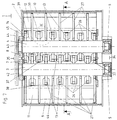
- the shredding device 1 is inserted into a housing 2 and has a left crushing shaft 3 and a right one Crushing shaft 4 on. Waves 3 and 4 are corresponding Fixed bearings 5 and 6 (see Fig. 2 and 7) assigned. With the reference numerals 7 and 8 are opposite the fixed bearings called lying coupling halves.
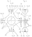
- a tool carrier 13 has radially extending arms 14, which serve as a tool holder head. On the arms 14 are in a seat 16 each clearer 15 and in corresponding Wear insert seats 18 and 20 the forward and back tear wear inserts 17 and 19 attached by welding.
- the arms 14 a have different radial lengths. So is a higher one Arm 21 and a lower arm 22 formed, with rotation the arms 21 and 22 have an inner and an outer effective diameter 40; 41 with different peripheral speeds adjusts, thereby improving the tear behavior of the device 1 results.
- Recesses or recesses 23 are located between the Arms 14 and ensure optimal material transport without the required mechanical stability of the tool carrier is restricted.
- a shaft opening 24 enables a corresponding circumferential Attach the individual tool carrier 13 to the Waves 3 and 4.
- the clearers 15 can be inclined Have 26 along the outer longitudinal edge, the helix angle Adjacent sweeper 14 arranged on a shaft are alternating, i.e. with corresponding reverse Sign chosen with respect to the respective longitudinal axis is.
- the clearing and crushing tines 27 shown in FIGS. 2 and 7 also take on a shredding function if the corresponding tool carrier 13 with the arms 14 of the move respective shafts 3 and 4 onto tines 27. At The direction of rotation is reversed accordingly in the Areas between the tines 27.
- the direction of rotation of the shafts 3 and 4 is symbolized by the reference numerals 28 and 29 or the corresponding arrow representations.
- the tools which are arranged on the tool carriers 13 of the two shafts 3 and 4 move towards one another, so that a central comminution region 37 results.
- a reversal of the direction of rotation clears out the central shredding area 37, material in the area 33 still being able to be shredded.
- the material fed in is torn and / or compressed, namely by appropriate forces between the tear-back wear inserts and the clearing and crushing tines 27.
- FIG. 5 shows a standardizable tool carrier blank 32 with clearing seat 16 and front 18 or rear wear insert seat.
- the area of the fixed bearings 5 and 6 is the storage area with 34 and the one for receiving the coupling with the reference symbol 35 marked. Located in the area of the coupling seat 35 also the coupling pin 42 and 43 and a wall 44 for Flange the gearbox and the corresponding part of the Housing wall 45.
- the helix angle according to FIG. 4 or as in FIG. 6 recognizable as detail X, is denoted by 36 and amounts to few angular degrees.
- the width of the scraper 15 is selected such that it laterally overlaps give a different grain size of the shredded, discharged material than is the case in an embodiment according to FIG. 7 with the scraper spacing 46.
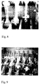
- FIG. 8 shows the spiral arrangement of the tool carriers over the circumference of the corresponding shaft, the clearing of the clearers extending on both sides of the tool carrier being recognizable in connection with the forward and backward tear wear insert.
- 9 shows parts of the two shafts with the tool carriers as well as lateral clearing and crushing tines.
- the side clearing and crushing tines can be different Have width, creating different distances between the tines and the corresponding scraper, which on Tool carriers are attached, result. That way it is possible for each shredding area, in particular between the middle shredding area or the middle shredding zone 37 and the lateral crushing areas 38 and 39 different grain sizes of the material crushed there to achieve, the grain size selection only by switching the direction of rotation with making effective either of the central comminution area 37 or the lateral shredding areas 38 and 39 can be done.
Landscapes
- Engineering & Computer Science (AREA)
- Food Science & Technology (AREA)
- Crushing And Pulverization Processes (AREA)
Priority Applications (1)
| Application Number | Priority Date | Filing Date | Title |
|---|---|---|---|
| DE2000111302 DE10011302A1 (de) | 1999-10-20 | 2000-03-09 | Zerkleinerungsvorrichtung mit zwei im wesentlichen parallel verlaufenden, motorisch angetriebenen Wellen |
Applications Claiming Priority (2)
| Application Number | Priority Date | Filing Date | Title |
|---|---|---|---|
| DE19847886 | 1998-10-21 | ||
| DE19847886 | 1998-10-21 |
Publications (2)
| Publication Number | Publication Date |
|---|---|
| EP0998980A1 true EP0998980A1 (fr) | 2000-05-10 |
| EP0998980B1 EP0998980B1 (fr) | 2003-04-02 |
Family
ID=7884776
Family Applications (1)
| Application Number | Title | Priority Date | Filing Date |
|---|---|---|---|
| EP99120794A Expired - Lifetime EP0998980B1 (fr) | 1998-10-21 | 1999-10-20 | Désintégrateur à arbres parallèles entraínés par moteur |
Country Status (6)
| Country | Link |
|---|---|
| US (1) | US6092751A (fr) |
| EP (1) | EP0998980B1 (fr) |
| AT (1) | ATE235964T1 (fr) |
| CA (1) | CA2255365C (fr) |
| DE (1) | DE59904826D1 (fr) |
| ES (1) | ES2195493T3 (fr) |
Cited By (7)
| Publication number | Priority date | Publication date | Assignee | Title |
|---|---|---|---|---|
| WO2002058851A3 (fr) * | 2000-10-30 | 2003-05-01 | Badger Bite Co | Lame de fragmentation |
| DE10344289B4 (de) * | 2003-09-23 | 2005-12-29 | Forus Gmbh | Vorrichtung zur Zerkleinerung von sperrigen Materialien, insbesondere von Müll |
| WO2008058009A1 (fr) * | 2006-11-06 | 2008-05-15 | Badger Shredding Products, Inc. | Lame réversible pour une broyeuse |
| CN112427133A (zh) * | 2020-12-11 | 2021-03-02 | 芜湖博威机械制造有限公司 | 一种可对钢管废料自动输送的钢管加工用回收处理装置 |
| CN113210059A (zh) * | 2021-05-21 | 2021-08-06 | 吴荣华 | 一种工业废弃固体颗粒高效率回收处理设备 |
| CN115529948A (zh) * | 2022-12-05 | 2022-12-30 | 哈尔滨重齿传动设备有限公司 | 一种改进刀片排列的生物质切撕一体机刀箱 |
| JP2023172005A (ja) * | 2022-05-23 | 2023-12-06 | 株式会社クボタ | 回転刃及び二軸回転式破砕装置 |
Families Citing this family (3)
| Publication number | Priority date | Publication date | Assignee | Title |
|---|---|---|---|---|
| WO2004071706A2 (fr) * | 2003-02-10 | 2004-08-26 | Morbark, Inc. | Machine a dechirer et a broyer des produits de dechets et son fonctionnement |
| DK176582B1 (da) * | 2005-06-22 | 2008-10-06 | M & J Ind As | Findelingsmaskine |
| CN105170264A (zh) * | 2015-10-29 | 2015-12-23 | 天津碎易得环保工程技术有限公司 | 一种液压剪切破碎机 |
Citations (4)
| Publication number | Priority date | Publication date | Assignee | Title |
|---|---|---|---|---|
| WO1991014501A1 (fr) * | 1990-03-21 | 1991-10-03 | Per Torp | Appareil a reduire les materiaux |
| DE9110457U1 (de) | 1991-08-23 | 1991-12-19 | Hammel, Norbert, 6301 Reiskirchen | Zerkleinerungsvorrichtung |
| DE9415955U1 (de) * | 1994-10-04 | 1994-11-24 | Beez, Frank, 57632 Rott | Zerkleinerungsvorrichtung |
| JPH0871443A (ja) * | 1994-09-06 | 1996-03-19 | Miike Tekkosho Kk | 破砕機 |
Family Cites Families (3)
| Publication number | Priority date | Publication date | Assignee | Title |
|---|---|---|---|---|
| DE4109467C2 (de) * | 1991-03-22 | 1997-03-27 | Schleicher & Co Int | Dokumentenvernichter |
| JP3188909B2 (ja) * | 1991-07-17 | 2001-07-16 | 松爾 中込 | 2軸破砕機 |
| US5516050A (en) * | 1995-02-27 | 1996-05-14 | Basf Corporation | Industrial Rotary Shredder |
-
1998
- 1998-12-09 US US09/208,315 patent/US6092751A/en not_active Expired - Fee Related
- 1998-12-09 CA CA002255365A patent/CA2255365C/fr not_active Expired - Fee Related
-
1999
- 1999-10-20 EP EP99120794A patent/EP0998980B1/fr not_active Expired - Lifetime
- 1999-10-20 ES ES99120794T patent/ES2195493T3/es not_active Expired - Lifetime
- 1999-10-20 AT AT99120794T patent/ATE235964T1/de not_active IP Right Cessation
- 1999-10-20 DE DE59904826T patent/DE59904826D1/de not_active Expired - Lifetime
Patent Citations (4)
| Publication number | Priority date | Publication date | Assignee | Title |
|---|---|---|---|---|
| WO1991014501A1 (fr) * | 1990-03-21 | 1991-10-03 | Per Torp | Appareil a reduire les materiaux |
| DE9110457U1 (de) | 1991-08-23 | 1991-12-19 | Hammel, Norbert, 6301 Reiskirchen | Zerkleinerungsvorrichtung |
| JPH0871443A (ja) * | 1994-09-06 | 1996-03-19 | Miike Tekkosho Kk | 破砕機 |
| DE9415955U1 (de) * | 1994-10-04 | 1994-11-24 | Beez, Frank, 57632 Rott | Zerkleinerungsvorrichtung |
Non-Patent Citations (1)
| Title |
|---|
| PATENT ABSTRACTS OF JAPAN vol. 1996, no. 07 31 July 1996 (1996-07-31) * |
Cited By (8)
| Publication number | Priority date | Publication date | Assignee | Title |
|---|---|---|---|---|
| WO2002058851A3 (fr) * | 2000-10-30 | 2003-05-01 | Badger Bite Co | Lame de fragmentation |
| US7131606B2 (en) | 2000-10-30 | 2006-11-07 | Badger Bite Co. | Comminution blade |
| DE10344289B4 (de) * | 2003-09-23 | 2005-12-29 | Forus Gmbh | Vorrichtung zur Zerkleinerung von sperrigen Materialien, insbesondere von Müll |
| WO2008058009A1 (fr) * | 2006-11-06 | 2008-05-15 | Badger Shredding Products, Inc. | Lame réversible pour une broyeuse |
| CN112427133A (zh) * | 2020-12-11 | 2021-03-02 | 芜湖博威机械制造有限公司 | 一种可对钢管废料自动输送的钢管加工用回收处理装置 |
| CN113210059A (zh) * | 2021-05-21 | 2021-08-06 | 吴荣华 | 一种工业废弃固体颗粒高效率回收处理设备 |
| JP2023172005A (ja) * | 2022-05-23 | 2023-12-06 | 株式会社クボタ | 回転刃及び二軸回転式破砕装置 |
| CN115529948A (zh) * | 2022-12-05 | 2022-12-30 | 哈尔滨重齿传动设备有限公司 | 一种改进刀片排列的生物质切撕一体机刀箱 |
Also Published As
| Publication number | Publication date |
|---|---|
| CA2255365C (fr) | 2004-05-25 |
| ATE235964T1 (de) | 2003-04-15 |
| CA2255365A1 (fr) | 2000-04-21 |
| ES2195493T3 (es) | 2003-12-01 |
| DE59904826D1 (de) | 2003-05-08 |
| US6092751A (en) | 2000-07-25 |
| EP0998980B1 (fr) | 2003-04-02 |
Similar Documents
| Publication | Publication Date | Title |
|---|---|---|
| EP0529221B1 (fr) | Dispositif de broyage | |
| CH622717A5 (fr) | ||
| EP1570919B1 (fr) | Appareil pour la séparation de matériaux substantiellement solides | |
| EP0998980B1 (fr) | Désintégrateur à arbres parallèles entraínés par moteur | |
| DE2256267B2 (de) | Mit Scherwirkung arbeitender Zerkleinerer | |
| CH659405A5 (de) | Zerkleinerungsvorrichtung fuer abfall. | |
| DE102008039258A1 (de) | Zerkleinerungsmaschine | |
| EP0291774B1 (fr) | Déchiqueteur à lames rotatives | |
| EP0037036B1 (fr) | Déchiqueteur rotatif pour le broyage de déchets | |
| EP3195934B1 (fr) | Dispositif de broyage et procédé de fonctionnement d'un tel dispositif de broyage | |
| EP0713726A2 (fr) | Broyeur pour copeaux métalliques | |
| CH667220A5 (de) | Hammerbrecher mit zwischen den rotorscheiben angeordneten haemmern. | |
| EP1904236A1 (fr) | Dispositif de comminution comportant plusieurs arbres rotatifs ou oscillants, essentiellement paralleles, entraines par moteur | |
| EP2549892B1 (fr) | Porte-couteaux pour dispositif de désintégration de matière organique | |
| DE19652323A1 (de) | Schneidsatz für eine Schneckenfördereinrichtung | |
| DE2814778C3 (de) | Zerkleinerungsmaschine für Schüttgüter | |
| DE102016122337A1 (de) | Mahlsteinanordnung für ein Scheibenmahlwerk zur Zerkleinerung von Mahlgut | |
| DE10015220A1 (de) | Zerkleinerungsvorrichtung mit zwei im wesentlichen parallel verlaufenden, motorisch angetriebenen Wellen | |
| AT399844B (de) | Filtervorrichtung, insbesondere für thermoplastische kunststoffschmelzen | |
| DE202011103394U1 (de) | Mühle zur Zerkleinerung von Mahlgut | |
| DE9415955U1 (de) | Zerkleinerungsvorrichtung | |
| DE69203681T2 (de) | Zerstückelungsvorrichtung. | |
| DE10018005A1 (de) | Verfahren und Vorrichtung zum Pulverisieren von spanartigem Material | |
| DE19530428C1 (de) | Granulatmühle | |
| EP0913189A2 (fr) | Mélangeur-broyeur et méthode d'utilisation de ce dispositif pour des matériaux déchets, particulièrement pour des matériaux déchets biodégradables |
Legal Events
| Date | Code | Title | Description |
|---|---|---|---|
| PUAI | Public reference made under article 153(3) epc to a published international application that has entered the european phase |
Free format text: ORIGINAL CODE: 0009012 |
|
| AK | Designated contracting states |
Kind code of ref document: A1 Designated state(s): AT BE CH CY DE DK ES FI FR GB GR IE IT LI LU MC NL PT SE |
|
| AX | Request for extension of the european patent |
Free format text: AL;LT;LV;MK;RO;SI |
|
| 17P | Request for examination filed |
Effective date: 20000522 |
|
| AKX | Designation fees paid |
Free format text: AT BE CH CY DE DK ES FI FR GB GR IE IT LI LU MC NL PT SE |
|
| GRAH | Despatch of communication of intention to grant a patent |
Free format text: ORIGINAL CODE: EPIDOS IGRA |
|
| GRAH | Despatch of communication of intention to grant a patent |
Free format text: ORIGINAL CODE: EPIDOS IGRA |
|
| GRAA | (expected) grant |
Free format text: ORIGINAL CODE: 0009210 |
|
| AK | Designated contracting states |
Designated state(s): AT BE CH CY DE DK ES FI FR GB GR IE IT LI LU MC NL PT SE |
|
| PG25 | Lapsed in a contracting state [announced via postgrant information from national office to epo] |
Ref country code: FI Free format text: LAPSE BECAUSE OF FAILURE TO SUBMIT A TRANSLATION OF THE DESCRIPTION OR TO PAY THE FEE WITHIN THE PRESCRIBED TIME-LIMIT Effective date: 20030402 |
|
| REG | Reference to a national code |
Ref country code: GB Ref legal event code: FG4D Free format text: NOT ENGLISH |
|
| REG | Reference to a national code |
Ref country code: CH Ref legal event code: EP |
|
| REG | Reference to a national code |
Ref country code: IE Ref legal event code: FG4D Free format text: GERMAN |
|
| REF | Corresponds to: |
Ref document number: 59904826 Country of ref document: DE Date of ref document: 20030508 Kind code of ref document: P |
|
| REG | Reference to a national code |
Ref country code: CH Ref legal event code: NV Representative=s name: ISLER & PEDRAZZINI AG |
|
| GBT | Gb: translation of ep patent filed (gb section 77(6)(a)/1977) |
Effective date: 20030512 |
|
| PG25 | Lapsed in a contracting state [announced via postgrant information from national office to epo] |
Ref country code: SE Free format text: LAPSE BECAUSE OF FAILURE TO SUBMIT A TRANSLATION OF THE DESCRIPTION OR TO PAY THE FEE WITHIN THE PRESCRIBED TIME-LIMIT Effective date: 20030702 Ref country code: PT Free format text: LAPSE BECAUSE OF FAILURE TO SUBMIT A TRANSLATION OF THE DESCRIPTION OR TO PAY THE FEE WITHIN THE PRESCRIBED TIME-LIMIT Effective date: 20030702 Ref country code: DK Free format text: LAPSE BECAUSE OF FAILURE TO SUBMIT A TRANSLATION OF THE DESCRIPTION OR TO PAY THE FEE WITHIN THE PRESCRIBED TIME-LIMIT Effective date: 20030702 |
|
| REG | Reference to a national code |
Ref country code: GR Ref legal event code: EP Ref document number: 20030402040 Country of ref document: GR |
|
| PG25 | Lapsed in a contracting state [announced via postgrant information from national office to epo] |
Ref country code: LU Free format text: LAPSE BECAUSE OF NON-PAYMENT OF DUE FEES Effective date: 20031020 Ref country code: CY Free format text: LAPSE BECAUSE OF FAILURE TO SUBMIT A TRANSLATION OF THE DESCRIPTION OR TO PAY THE FEE WITHIN THE PRESCRIBED TIME-LIMIT Effective date: 20031020 |
|
| PG25 | Lapsed in a contracting state [announced via postgrant information from national office to epo] |
Ref country code: MC Free format text: LAPSE BECAUSE OF NON-PAYMENT OF DUE FEES Effective date: 20031031 Ref country code: BE Free format text: LAPSE BECAUSE OF NON-PAYMENT OF DUE FEES Effective date: 20031031 |
|
| ET | Fr: translation filed | ||
| PLBE | No opposition filed within time limit |
Free format text: ORIGINAL CODE: 0009261 |
|
| STAA | Information on the status of an ep patent application or granted ep patent |
Free format text: STATUS: NO OPPOSITION FILED WITHIN TIME LIMIT |
|
| 26N | No opposition filed |
Effective date: 20040105 |
|
| BERE | Be: lapsed |
Owner name: *EUREC TECHNOLOGY G.M.B.H. ENTSORGUNGSANLAGEN Effective date: 20031031 |
|
| REG | Reference to a national code |
Ref country code: CH Ref legal event code: PCAR Free format text: ISLER & PEDRAZZINI AG;POSTFACH 1772;8027 ZUERICH (CH) |
|
| PGFP | Annual fee paid to national office [announced via postgrant information from national office to epo] |
Ref country code: GR Payment date: 20071005 Year of fee payment: 9 |
|
| PG25 | Lapsed in a contracting state [announced via postgrant information from national office to epo] |
Ref country code: GR Free format text: LAPSE BECAUSE OF NON-PAYMENT OF DUE FEES Effective date: 20090505 |
|
| PGFP | Annual fee paid to national office [announced via postgrant information from national office to epo] |
Ref country code: ES Payment date: 20091029 Year of fee payment: 11 Ref country code: CH Payment date: 20091030 Year of fee payment: 11 Ref country code: AT Payment date: 20091027 Year of fee payment: 11 |
|
| PGFP | Annual fee paid to national office [announced via postgrant information from national office to epo] |
Ref country code: NL Payment date: 20091028 Year of fee payment: 11 |
|
| PGFP | Annual fee paid to national office [announced via postgrant information from national office to epo] |
Ref country code: FR Payment date: 20100128 Year of fee payment: 11 |
|
| PGFP | Annual fee paid to national office [announced via postgrant information from national office to epo] |
Ref country code: GB Payment date: 20101029 Year of fee payment: 12 Ref country code: IT Payment date: 20101030 Year of fee payment: 12 |
|
| REG | Reference to a national code |
Ref country code: NL Ref legal event code: V1 Effective date: 20110501 |
|
| REG | Reference to a national code |
Ref country code: CH Ref legal event code: PL |
|
| PG25 | Lapsed in a contracting state [announced via postgrant information from national office to epo] |
Ref country code: CH Free format text: LAPSE BECAUSE OF NON-PAYMENT OF DUE FEES Effective date: 20101031 Ref country code: FR Free format text: LAPSE BECAUSE OF NON-PAYMENT OF DUE FEES Effective date: 20101102 Ref country code: LI Free format text: LAPSE BECAUSE OF NON-PAYMENT OF DUE FEES Effective date: 20101031 |
|
| REG | Reference to a national code |
Ref country code: FR Ref legal event code: ST Effective date: 20110630 |
|
| PG25 | Lapsed in a contracting state [announced via postgrant information from national office to epo] |
Ref country code: NL Free format text: LAPSE BECAUSE OF NON-PAYMENT OF DUE FEES Effective date: 20110501 Ref country code: AT Free format text: LAPSE BECAUSE OF NON-PAYMENT OF DUE FEES Effective date: 20101020 |
|
| REG | Reference to a national code |
Ref country code: ES Ref legal event code: FD2A Effective date: 20111118 |
|
| PG25 | Lapsed in a contracting state [announced via postgrant information from national office to epo] |
Ref country code: ES Free format text: LAPSE BECAUSE OF NON-PAYMENT OF DUE FEES Effective date: 20101021 |
|
| PGFP | Annual fee paid to national office [announced via postgrant information from national office to epo] |
Ref country code: IE Payment date: 20111026 Year of fee payment: 13 |
|
| GBPC | Gb: european patent ceased through non-payment of renewal fee |
Effective date: 20121020 |
|
| REG | Reference to a national code |
Ref country code: IE Ref legal event code: MM4A |
|
| PG25 | Lapsed in a contracting state [announced via postgrant information from national office to epo] |
Ref country code: IE Free format text: LAPSE BECAUSE OF NON-PAYMENT OF DUE FEES Effective date: 20121020 Ref country code: GB Free format text: LAPSE BECAUSE OF NON-PAYMENT OF DUE FEES Effective date: 20121020 |
|
| PG25 | Lapsed in a contracting state [announced via postgrant information from national office to epo] |
Ref country code: IT Free format text: LAPSE BECAUSE OF NON-PAYMENT OF DUE FEES Effective date: 20121020 |
|
| REG | Reference to a national code |
Ref country code: DE Ref legal event code: R082 Ref document number: 59904826 Country of ref document: DE Representative=s name: MEISSNER BOLTE PATENTANWAELTE RECHTSANWAELTE P, DE Ref country code: DE Ref legal event code: R081 Ref document number: 59904826 Country of ref document: DE Owner name: EUREC ENVIRONMENTAL TECHNOLOGY GMBH, DE Free format text: FORMER OWNER: EUREC TECHNOLOGY GMBH DEVELOPMENT & DESIGN, 36460 MERKERS, DE |
|
| PGFP | Annual fee paid to national office [announced via postgrant information from national office to epo] |
Ref country code: DE Payment date: 20181030 Year of fee payment: 20 |
|
| REG | Reference to a national code |
Ref country code: DE Ref legal event code: R071 Ref document number: 59904826 Country of ref document: DE |