EP0999023A1 - Dispositif d'entrainement de moule metallique pour le moulage, dispositif de maintien, et procede de maintien - Google Patents
Dispositif d'entrainement de moule metallique pour le moulage, dispositif de maintien, et procede de maintien Download PDFInfo
- Publication number
- EP0999023A1 EP0999023A1 EP99917072A EP99917072A EP0999023A1 EP 0999023 A1 EP0999023 A1 EP 0999023A1 EP 99917072 A EP99917072 A EP 99917072A EP 99917072 A EP99917072 A EP 99917072A EP 0999023 A1 EP0999023 A1 EP 0999023A1
- Authority
- EP
- European Patent Office
- Prior art keywords
- die
- unit
- molding
- cylinder unit
- main cylinder
- Prior art date
- Legal status (The legal status is an assumption and is not a legal conclusion. Google has not performed a legal analysis and makes no representation as to the accuracy of the status listed.)
- Withdrawn
Links
Images







Classifications
-
- B—PERFORMING OPERATIONS; TRANSPORTING
- B29—WORKING OF PLASTICS; WORKING OF SUBSTANCES IN A PLASTIC STATE IN GENERAL
- B29C—SHAPING OR JOINING OF PLASTICS; SHAPING OF MATERIAL IN A PLASTIC STATE, NOT OTHERWISE PROVIDED FOR; AFTER-TREATMENT OF THE SHAPED PRODUCTS, e.g. REPAIRING
- B29C45/00—Injection moulding, i.e. forcing the required volume of moulding material through a nozzle into a closed mould; Apparatus therefor
- B29C45/17—Component parts, details or accessories; Auxiliary operations
- B29C45/46—Means for plasticising or homogenising the moulding material or forcing it into the mould
- B29C45/56—Means for plasticising or homogenising the moulding material or forcing it into the mould using mould parts movable during or after injection, e.g. injection-compression moulding
- B29C45/561—Injection-compression moulding
-
- B—PERFORMING OPERATIONS; TRANSPORTING
- B29—WORKING OF PLASTICS; WORKING OF SUBSTANCES IN A PLASTIC STATE IN GENERAL
- B29C—SHAPING OR JOINING OF PLASTICS; SHAPING OF MATERIAL IN A PLASTIC STATE, NOT OTHERWISE PROVIDED FOR; AFTER-TREATMENT OF THE SHAPED PRODUCTS, e.g. REPAIRING
- B29C45/00—Injection moulding, i.e. forcing the required volume of moulding material through a nozzle into a closed mould; Apparatus therefor
- B29C45/17—Component parts, details or accessories; Auxiliary operations
- B29C45/46—Means for plasticising or homogenising the moulding material or forcing it into the mould
- B29C45/56—Means for plasticising or homogenising the moulding material or forcing it into the mould using mould parts movable during or after injection, e.g. injection-compression moulding
- B29C45/561—Injection-compression moulding
- B29C2045/563—Enlarging the mould cavity during injection
-
- B—PERFORMING OPERATIONS; TRANSPORTING
- B29—WORKING OF PLASTICS; WORKING OF SUBSTANCES IN A PLASTIC STATE IN GENERAL
- B29C—SHAPING OR JOINING OF PLASTICS; SHAPING OF MATERIAL IN A PLASTIC STATE, NOT OTHERWISE PROVIDED FOR; AFTER-TREATMENT OF THE SHAPED PRODUCTS, e.g. REPAIRING
- B29C45/00—Injection moulding, i.e. forcing the required volume of moulding material through a nozzle into a closed mould; Apparatus therefor
- B29C45/17—Component parts, details or accessories; Auxiliary operations
- B29C45/46—Means for plasticising or homogenising the moulding material or forcing it into the mould
- B29C45/56—Means for plasticising or homogenising the moulding material or forcing it into the mould using mould parts movable during or after injection, e.g. injection-compression moulding
- B29C45/561—Injection-compression moulding
- B29C2045/564—Compression drive means acting independently from the mould closing and clamping means
-
- B—PERFORMING OPERATIONS; TRANSPORTING
- B29—WORKING OF PLASTICS; WORKING OF SUBSTANCES IN A PLASTIC STATE IN GENERAL
- B29C—SHAPING OR JOINING OF PLASTICS; SHAPING OF MATERIAL IN A PLASTIC STATE, NOT OTHERWISE PROVIDED FOR; AFTER-TREATMENT OF THE SHAPED PRODUCTS, e.g. REPAIRING
- B29C45/00—Injection moulding, i.e. forcing the required volume of moulding material through a nozzle into a closed mould; Apparatus therefor
- B29C45/17—Component parts, details or accessories; Auxiliary operations
- B29C45/46—Means for plasticising or homogenising the moulding material or forcing it into the mould
- B29C45/56—Means for plasticising or homogenising the moulding material or forcing it into the mould using mould parts movable during or after injection, e.g. injection-compression moulding
- B29C45/561—Injection-compression moulding
- B29C2045/565—Closing of the mould during injection
Definitions
- the present invention relates to a molding die drive unit for advancing and retracting at least a part of a die to change a volume of a cavity provided in the die for compressing or expanding (enlarging volume) a resin in the die during injection molding, injection compression molding, press molding, large blow gas-injection molding, multi-layered molding, foam molding thereof, and expansion molding of glass-fiber containing resin; a molding unit incorporating the molding die drive unit; and a molding method using the molding unit.
- molten resin is loaded inside a die closed with a predetermined compression margin retained and, subsequently, a compression force is applied to the molten resin filled in the die by clamping the die for rendering shape.
- the molding process can be conducted by a low resin injection pressure and in-mold pressure can be made uniform, warp and distortion are not caused to the molding product, thus being capable of obtaining molding products having good shape even with small thickness and causing less damage to a surface member during surface member integrating molding.
- a molding machine used for the injection compression molding generally has a clamp unit for advancing a movable die provided to the molding machine movably toward a stationary die fixed to the molding machine, and a compression unit for compressing the molten resin filled inside the die.
- a conventional compression unit has a movable portion for increasing and decreasing a volume of a die cavity inside the die and a pin abutted to the movable portion through which the movable portion is advanced to reduce the volume of the cavity so that the molten resin filled inside the die is compressed.
- a pair of slant member having mutually touching slant surfaces slanting relative to advancing direction of the movable portion is disposed along an advancing direction thereof and one of the slant members is moved in a direction orthogonal with the advancing direction of the movable portion to generate compression force.
- the Applicant of the present application has proposed a compression unit 75 having unitized mechanism for pressing a movable die 71 toward a stationary die 72 being capable of attaching and detaching between the movable die 71 and a clamp unit 74 (Japanese Patent Publication Laid-Open No. Hei 7-164500).
- the compression unit 75 has a pair of slant member 77 and 78 disposed along the compressing direction both having a slant surface 76 slanting toward compressing direction.
- the slant member 78 on the clamp unit 74 side is advanced toward the slant member 77 by a cylinder unit 79 to generate compression force.
- the entire thickness can be made relatively small as compared to the unit described in the Japanese Patent Publication Laid-Open No. Sho 57-95429 etc., which can be attached to an ordinary injection molding machine together with the die, thereby enabling injection compression molding even with an ordinary die having no movable portion installed therein so that general purpose properties of the molding machine can be improved.
- An object of the present invention is to provide a molding die drive unit being capable of compressing and expanding the molten resin injected into the die and having reduced thickness and superior mechanical efficiency, a molding unit installed with the molding die drive unit and molding method using the molding unit.
- the present invention is a unitized die driving unit detachably attached to any one of the stationary die and the movable die that intends to achieve the above object by providing a main cylinder used for pressurization and a plurality of sub cylinder unit used for pressurization and high-speed movement around the main cylinder unit.
- a molding die drive unit is for forming a cavity between a stationary die and a movable die for molten resin to be loaded, the molding die drive unit being detachably attached to either the stationary die or the movable die for moving a part of or entirety of at least one of the stationary die and the movable die to be advanced and retracted relative to the cavity.
- the molding die drive unit is characterized in having: a large-diameter main cylinder unit; and a plurality of small-diameter sub cylinder unit disposed around the main cylinder unit being spaced apart with each other.
- the molding die drive unit advances and retracts a part of entirety of the stationary die or the movable die, or, a part of the stationary die or the movable die relative to the cavity.
- Advancement or retraction of the part of the stationary die or the movable die refers to advancement and retraction of a slide die when the dies are constructed of die body and the slide die disposed slidably relative to the die body.
- the molten resin is injected into the cavity after closing the stationary die and the movable die.
- the main cylinder unit and the sub cylinder unit are driven to advance and retract at least a part of the stationary die and the movable die relative to the cavity to compress or expand (volume enlargement) the molten resin in the cavity for rendering shape.
- Small-diameter sub cylinder unit is used for advancing and retracting at least a part of the stationary die or the movable die to a predetermined position.
- hydraulic fluid hydraulic pressure
- the main cylinder unit advances and retracts in accordance with advancement and retraction of the sub cylinder unit.
- the injection compression molding is possible by advancing at least a part of the stationary die or the movable die alter initiating the injection of the molten resin into the cavity, and injection expansion molding and injection compression expansion molding is possible by advancing and retracting a part of the stationary die or the movable die.
- the large-diameter main cylinder unit is mainly used for pressurizing the molten resin, uniformity of strength applied to the entire molten resin can be secured, thereby securing parallelization between the movable die and the stationary die.
- the large-diameter main cylinder unit is advanced only in pressurizing the molten resin and only the small-diameter sub cylinder unit is driven in retracting at least a part of the stationary die or the movable die, operation circuit for retracting the main cylinder unit is not necessary.
- the cylinder units can be constructed of thin unit having large mechanical output, which can be attached to an ordinary injection molding machine together with the die.
- the main cylinder unit may preferably be connected to a main cylinder driving mechanism, the main cylinder driving mechanism having: a main cylinder flow channel disposed between a hydraulic fluid feeder for feeding hydraulic fluid in a hydraulic tank and the main cylinder unit; and a main cylinder switching valve provided to the main cylinder flow channel for switching position thereof between a position for supplying the hydraulic fluid to the main cylinder unit to advance the main cylinder unit and a position for blocking supply of the hydraulic fluid to the main cylinder unit and for returning the hydraulic fluid in the main cylinder unit to the hydraulic tank.
- the main cylinder driving mechanism having: a main cylinder flow channel disposed between a hydraulic fluid feeder for feeding hydraulic fluid in a hydraulic tank and the main cylinder unit; and a main cylinder switching valve provided to the main cylinder flow channel for switching position thereof between a position for supplying the hydraulic fluid to the main cylinder unit to advance the main cylinder unit and a position for blocking supply of the hydraulic fluid to the main cylinder unit and for returning the hydraulic fluid in the main cylinder unit to the hydraulic tank.
- the circulation of the hydraulic fluid between the main cylinder unit and the hydraulic tank can be easily allowed and blocked by the main cylinder switching valve.
- the molding die drive unit may further include a reserve tank disposed adjacent to the main cylinder unit and an on-off valve provided between the main cylinder unit and the reserve tank for allowing or blocking circulation of the hydraulic fluid between the main cylinder unit and the reserve tank.
- the reserve tank may be intercommunicated with the main cylinder unit through the on-off valve.
- the exclusive reserve tank is used for supplying the main cylinder unit with hydraulic fluid and returning the hydraulic fluid from the main cylinder unit.
- the reserve tank in communication with the main cylinder unit may be disposed adjacent to the main cylinder unit.
- the hydraulic fluid circulates smoothly between the reserve tank and the main cylinder unit when at least a part of the stationary die and the movable die advances and retracts at a high speed so that responsivity of the die movement can be improved and the size of the external hydraulic tank and the hydraulic pump can be reduced.
- the sub cylinder unit may be connected to a sub cylinder driving mechanism, the sub cylinder driving mechanism having: a sub cylinder flow channel provided between the hydraulic fluid feeder and the sub cylinder unit; a sub cylinder switching valve provided to the sub cylinder flow channel for switching a position thereof among a position for supplying the hydraulic fluid to the sub cylinder unit to advance the sub cylinder unit, a position for supplying the hydraulic fluid to the sub cylinder unit to retract the sub cylinder unit and a position for blocking intercommunication of the hydraulic fluid between the sub cylinder unit and the hydraulic fluid feeder.
- the sub cylinder driving mechanism having: a sub cylinder flow channel provided between the hydraulic fluid feeder and the sub cylinder unit; a sub cylinder switching valve provided to the sub cylinder flow channel for switching a position thereof among a position for supplying the hydraulic fluid to the sub cylinder unit to advance the sub cylinder unit, a position for supplying the hydraulic fluid to the sub cylinder unit to retract the sub cylinder unit and a position for blocking intercommunication of the hydraulic fluid between the sub cylinder unit and the hydraulic
- the molding process can be rapidly conducted.
- an opening may be formed along axis center of the main cylinder unit.
- the resin injection nozzle can be inserted from the opening, so that disposition on the stationary die side is possible. And when attached to the movable die side, the ejector rod can be inserted thereto, thereby facilitating ejection of molding products.
- a molding unit according to the present invention has the above molding die drive unit between a movable platen having the movable die thereon and a stationary platen having the stationary die thereon or, alternatively, the molding die drive unit may be attached to the movable platen or the stationary platen. Further, a pressure-receiving block may be provided between the movable platen and the stationary platen.
- the pressure-receiving block provided to the stationary platen abuts to the pressure-receiving block provided to the movable platen in advancing the movable platen to receive high-pressure clamping force.
- the pressure-receiving blocks secure parallelization between the stationary die and the movable die attached to the platens, thereby conducting appropriate injection operation.
- the pressure-receiving block is important for increasing and decreasing the cavity volume by advancing and retracting the entire movable die.
- a molding method for molding resin according to the present invention is a molding method using the above molding unit, which is characterized in having the steps of: injecting a molten resin to the cavity; and advancing and retracting a part or an entirety of at least one of the stationary die and the movable die relative to the cavity at any time period after initiation of injection.
- the sub cylinder unit may be driven to advance the part or the entirety of at least one of the stationary die or the movable die at a high speed relative to the cavity while intercommunicating the main cylinder unit with the hydraulic tank or the reserve tank, and, subsequently, hydraulic pressure may be applied to both of the main cylinder unit and the sub cylinder unit while blocking intercommunication of the main cylinder unit with the hydraulic tank or the reserve tank to pressurize the molten resin loaded in the cavity to advance the part or the entirety of at least one of the stationary die or the movable die relative to the cavity.
- injection compression molding can be appropriately conducted.
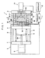
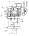
- Fig. 1 shows an injection molding unit 1 according to first embodiment of the present invention.
- the injection molding unit 1 conducts molding process by a die 10 divided into a stationary die 10A and a movable die 10B.
- the die 10 is closed while retaining moving distance of a dimension ⁇ as a compression margin of the movable die 10B relative to the stationary die 10A, so that a cavity 10C for loading a molten resin 2 injected from an injection unit 1A is formed therein.
- the loaded molten resin 2 is compressed to be filled for rendering shape by pressing the movable die 10B by a molding die drive unit 20 attached at the back of the movable die 10B.
- the injection molding unit 1 has a stationary die plate 3 as a stationary platen having the stationary die 10A fixed thereto, a movable die plate 4 as a movable platen having the movable die 10B and the die driving unit 20, and a clamp unit 5 for advancing the movable die plate 4 toward the stationary die plate 3.
- the movable die plate 4 is slidable along a tie-bar 8 spanning between a stationary plate 7 having a clamping hydraulic cylinder unit 6 fixed thereto and a stationary die plate 3.
- the clamp unit 5 has a toggle mechanism 9 having a piston rod 6A of the hydraulic cylinder unit 6, where pressing force of the hydraulic cylinder unit 6 is strengthened by the toggle mechanism 9 to advance the movable die plate 4 to clamp the die 10.
- Clamping-pressure receiving blocks 3A and 3B are provided between the movable die plate 4 and the stationary die plate 3.
- the clamping-pressure receiving block 3A provided on the stationary die plate 3 side abuts to the pressure-receiving block 3B provided on the movable die plate 4 side to receive high-pressure clamping force of the toggle mechanism 9. Degree of parallelization between the die plates 3 and 4 can be secured by the clamping-pressure receiving blocks 3A and 3B.
- the molding die drive unit 20 has a large-diameter main cylinder unit. 21 attached between the movable die 10B and the movable die plate 4, a small-diameter sub cylinder unit 22 disposed around the main cylinder unit 21, a hydraulic unit 11 for driving the cylinder units 21 and 22, and a controller 12 for controlling the die driving unit 20.
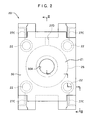
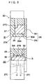
- FIG. 2 Detailed arrangement of the molding die drive unit 20 is shown in Fig. 2 to Fig. 4.
- Fig. 2 is a front elevation of the molding die drive unit 20
- Fig. 3 is a cross section taken along III-III line in Fig. 2 viewed in arrow-indicating direction
- Fig. 4 is a summarized block diagram showing a hydraulic unit 11 for driving the molding die drive unit 20.
- the main cylinder unit 21 includes a cylinder member 25 and a piston member 26 advanceable and retractable relative to the cylinder member 25.
- the cylinder member 25 has a thick flat-plate member 27 having a cylindrical cut-out 27A at a central portion thereof and a core member 28 provided at a central portion of the flat-plate member 27.
- An opening 28A is formed on the core member 28 along an axis center of the main cylinder unit 21 continuously with the cut-out 27A.
- the piston member 26 includes a ring-shaped member 29 slidably disposed between the flat-plate member 27 and the core member 28, and an attachment plate 30 fixed at an end of the ring-shaped member 29 for the movable die 10B to be attached thereon.
- An opening 30A continuous with the opening 28A is formed at a position of the attachment plate 30 corresponding to an axis center of the ring-shaped member 29.
- the sub cylinder unit 22 is disposed around the main cylinder unit 21 in plural (with number of ⁇ . Four in the figure) spaced apart with each other, which includes four cylinder portions 27B formed on the flat-plate member 27 and piston members 31 respectively disposed on the cylinder portion 27B to be slidable.
- the cylinder portion 27B is connected to the hydraulic unit 11 through a flow channel 27C formed on the flat-plate member 27.
- the sub cylinder units 22 are preferably disposed at a regular interval as shown in the figure.
- the piston member 31 has a projection 31A at a center thereof along a circumferential direction.
- the projection 31A is prevented from being fallen off by a pair of stopper 32 provided on the cylinder portion 27B.
- a flow channel 27C for supplying hydraulic fluid between the stoppers 32 and the projection 31A is formed on the flat plate member 27.
- the attachment plate 30 is fixed on an advancement-side end of the piston member 31.
- the main cylinder 21 is advanced for pressurizing the molten resin loaded in the cavity 10C, and the sub cylinder unit 22 is used not only for pressurizing the molten resin, but also for moving the movable die 10B at a high speed.
- an effective sectional area of the main cylinder unit 21 is A
- advancement-side effective sectional area of one sub cylinder unit 22 is B
- retraction-side effective sectional area thereof is C
- cylinder effective sectional area of the movable die 10B during high-speed advancement is B* ⁇
- cylinder effective sectional area of the movable die 10B during high-speed retraction is C* ⁇
- cylinder effective sectional area while pressurizing the molten resin is (A+B* ⁇ ).
- moving speed is high-speed advancement (retraction)>>pressurization
- moving force is pressurization >> high-speed advancement (retraction).
- a conduit line 27D for intercommunicating the hydraulic unit 11 and a space between the cylinder member 25 and the piston member 26 is formed on the flat-plate member 27.
- the hydraulic unit 11 includes a hydraulic tank 11A having the hydraulic fluid contained therein, a hydraulic pump 36 as a hydraulic fluid feeder for supplying the hydraulic fluid from the hydraulic tank 11A, a main cylinder driving mechanism 37 for driving the main cylinder unit 21 by the hydraulic fluid supplied from the hydraulic pump 36, and a sub cylinder driving mechanism 38 for driving the sub cylinder unit 22 by the hydraulic fluid supplied by the hydraulic pump 36.
- the main cylinder driving mechanism 37 has a main cylinder flow channel 39 for circulating the hydraulic oil supplied from the hydraulic pump 36 to the main cylinder unit 21, and a main cylinder switching valve 40 provided to the main cylinder flow channel 39 for switching a position thereof between a position for supplying the hydraulic fluid from the hydraulic pump 36 to the main cylinder unit 21 to advance the main cylinder unit 21 and a position for blocking the supply of the hydraulic fluid to the main cylinder unit 21 and for returning the hydraulic fluid in the main cylinder unit 21 to the hydraulic tank 11A.
- the main cylinder flow channel 39 is connected to a flow channel 27D provided to the molding die drive unit 20 through a hydraulic hose 41.
- the flow channel 27D is in communication with a space between the cylinder member 25 and the piston member 26 of the main cylinder unit 21.
- the main cylinder switching valve 40 is a solenoid valve.
- the sub cylinder driving mechanism 38 includes a sub cylinder flow channel 43 provided between the hydraulic pump 36 and the sub cylinder unit 22, and a sub cylinder switching valve 44 provided to the flow channel 43.
- the sub cylinder flow channel 43 is connected to the flow channel 27C provided to the molding die drive unit 20 through a hydraulic hose 42.
- the sub cylinder switching valve 44 is capable of switching between three positions: a position for supplying the hydraulic fluid to the sub cylinder unit 22 to advance the sub cylinder unit 22; a position for supplying hydraulic fluid to the sub cylinder unit 22 to retract the sub cylinder unit 22; and a neutral position.
- molding method molding process
- the die 10 and the die driving unit 20 are attached to a general-type injection molding unit 1 together with clamping-pressure receiving blocks 3A and 3B to construct the injection compression molding unit as shown in Fig. 1.
- the piston members 26 and 31 of the molding die drive unit 20 are retracted.
- the clamp unit 5 is initially driven to move the movable die plate 4 to the stationary die plate 3 and the die 10 is closed while retaining a compression margin of a dimension ⁇ on the movable die 10B.
- the dimension ⁇ can be set within a range of, for instance, 0.1mm to 100mm.
- the clamping-pressure receiving blocks 3A and 3B are provided between the movable die plate 4 and the stationary die plate 3, the die plates 3 and 4 go parallel when the toggle mechanism 9 of the clamp unit 5 is fully extended and the parallelization of the die plates 3 and 4 are stably maintained. Consequently, the stationary die 10A and the movable die 10B are stabilized.
- the molten resin is injected from an injection nozzle of the injection unit 1A to the internal cavity 10C of the die 10 so as not to fill the cavity.
- the injected molten resin is thermoplastic, which may be general-purpose resin such as polyethylene, polypropylene, polystyrene, ABS, engineering plastics such as polycarbonate, polyamide, polyacetal, and compounds of the above resins with reinforcing agent such as glass fiber, carbon fiber and organic fiber, bulking agent such as talc and various additives, including all polymeric material capable of using for injection molding.
- thermoplastic which may be general-purpose resin such as polyethylene, polypropylene, polystyrene, ABS, engineering plastics such as polycarbonate, polyamide, polyacetal, and compounds of the above resins with reinforcing agent such as glass fiber, carbon fiber and organic fiber, bulking agent such as talc and various additives, including all polymeric material capable of using for injection molding.
- the molding die drive unit 20 After a predetermined time passes from initiating injection of the injection unit 1A or when an injection screw provided in the injection unit 1A reaches a predetermined position, the molding die drive unit 20 is driven.
- the drive of the molding die drive unit 20 may be conducted after injecting the resin or during injection, and the resin injection amount to the cavity 10C of the die 10 can be voluntarily set.
- driving speed takes precedence over driving force.
- the four sub cylinder units 22 are advanced to advance the movable die 10B at a high speed.
- the main cylinder flow channel 39 is intercommunicated with the hydraulic tank 11A by the main cylinder switching valve 40 and the position of the sub cylinder switching valve 44 is switched to supply the hydraulic fluid to the sub cylinder unit 22 to advance the sub cylinder unit 22.
- the hydraulic fluid is fed from the hydraulic pump 36 to the sub cylinder unit 22, so that the attachment plate 30 having the movable die 10B attached thereon is advanced at a high speed by the sub cylinder unit 22.
- an advancing force is generated to the piston member 26 of the main cylinder unit 21 in accordance with the advancement of the attachment plate 30, since the hydraulic fluid contained in the hydraulic tank 11A is flown into the main cylinder unit 21 through the conduit line 27D by switching the switching valve 40, the piston member 26 is advanced smoothly.
- the main cylinder switching valve 40 is operated to switch the position thereof to intercommunicate the main cylinder flow channel 39 with the hydraulic pump 36.
- the hydraulic fluid is fed from the hydraulic pump 36 not only to the sub cylinder unit 22 but also to the main cylinder unit 21, so that large force by the cylinder units 21 and 22 works on the movable die 10B to fill the entirety of the cavity 10C, with molten resin loaded to the cavity 10C between the movable die 10B and the stationary die 10A as shown in Fig. 7 from a condition being concentrated to a central portion of the cavity shown in Fig. 6.
- the molten resin While applying pressure to the molten resin by the molding die drive unit 20, the molten resin is cooled and solidified for a predetermined time period. When the molten resin is sufficiently solidifies alter the predetermined time, the clamp unit 5 is driven to retract the movable die plate 4 to open the die 10. Subsequently, the molding product is ejected from the inside of the die 10 to complete the molding process. Thereafter, the injection compression molding process is repeated as necessary.
- the cylinder units 21 and 22 are retracted during a time period from initiation of retracting the movable die plate 4 to initiation of next injection molding process.
- the position of the main cylinder switching valve 40 is switched to intercommunicate the main cylinder flow channel 39 with the hydraulic tank 11A, and the position of the sub cylinder switching valve 44 is switched to supply the hydraulic fluid to the sub cylinder unit 22 to retract the sub cylinder unit 22.
- the hydraulic fluid is fed from the hydraulic pump 36 to the sub cylinder unit 22 to retract the attachment plate 30 having the movable die 10B attached thereon at a high speed by the sub cylinder unit 22.
- a force for retracting the piston member 26 of the main cylinder unit 212 is caused.
- the hydraulic fluid contained in the main cylinder unit 21 by the switching valve 40 is returned to the inside of the hydraulic tank 11A through the conduit line 27D, the piston member 26 is retracted smoothly.
- third embodiment of the present invention will be described with reference to Fig. 15 and 16.
- a part of the movable die 10B is advanced and retracted by the die driving unit 20 and other arrangement of the third embodiment is the same as the second embodiment.
- the same reference numerals will be attached to the component identical with or similar to the first and the second embodiments to omit or simplify the description therefor.
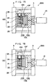
- Fig. 15 and Fig. 16 are cross sections respectively showing primary portion of an injection molding unit 200 having the molding die drive unit 120 installed therein.
- the basic arrangement of the injection molding unit 200 of the third embodiment such as the clamp unit 5, the hydraulic cylinder unit 6 and toggle mechanism 9 is the same as the injection molding unit 1 and 100 of the first and the second embodiment.
- the movable die 10B has a die body 10G fixed to the cylinder member 25 of the molding die drive unit 120 and having an opening at a central portion thereof, and a slide die 10F disposed at the opening of the die body 10G and being slidable relative to the cavity 10C.
- the slide die 10F is fixed to the attachment plate 30 of the molding die drive unit 120.
- the molding die drive unit 120 includes a large-diameter main cylinder unit 21, a small-diameter sub cylinder unit 22 disposed around the main cylinder unit 21, a reserve tank 23 in communication with the main cylinder unit 21, an on-off valve 24 for allowing and blocking the circulation of the hydraulic fluid between the reserve tank 23 and the main cylinder unit 21, a hydraulic unit 11 for driving the cylinder unit 21 and 22 (see Fig. 8), and a controller 12 for controlling the molding die drive unit 20 (see Fig. 8).
- expansible molten resin such as a resin including foaming agent and a resin including glass fiber can be injected into the cavity 10C of the die 10E as well as a normal molten resin.
- the molten resin having expansibility is used, as shown in Fig. 15, the molten resin is injected inside the die 10E while the slide die 10F advances to the stationary die 10A to fill the cavity in the die 10E with the molten resin. Subsequently, as shown in Fig. 16, the slide die 10F is retracted from the stationary die 10A to enlarge the cavity 10C to promote foaming of the foaming agent, thereby producing light-weight molding product by the expansion.
- effects similar to 2) to 9) of the second embodiment can be obtained and, in addition thereto, 10) effect being capable of partially applying compressive force to the molten resin injected into the die 10E and enlarging cavity 10C can be obtained.
- the present example was an experiment in which the injection molding unit 1, the molding die drive unit 20 and the molding process according to the first embodiment was used.
- the die used in the Example 1 was for forming a rectangular-plate molding product and had a side gate at a center of a short edge of the cavity. Respective dimensions of the molding products were 1000mm (vertical) * 500mm (horizontal) * 2mm (thick).
- a general-purpose horizontal injection molding unit having clamping force of 850t was used as the injection molding unit.
- the effective cross section A of the main cylinder unit 21 was 3060cm 2
- advancement-side effective cross section B of the sub cylinder unit 22 was 180cm 2
- retraction-side effective cross section C of the sub cylinder unit 22 was 230cm 2
- the number ⁇ of the sub cylinder unit 22 was four.
- the present example was an experiment in which the injection molding unit 100, molding die drive unit 120 and the molding process according to the second embodiment were used to produce molding product.
- the die used in the present embodiment was for forming a rectangular-plate molding product and had a side gate at a center of a short edge of the cavity.
- Respective dimensions of the molding products were 1000mm (vertical) * 500mm (horizontal;) * 2mm (thick).
- the general-purpose horizontal injection molding unit having clamping force of 850t was used as the injection molding unit as in the Example 1.
- the effective cross section A of the main cylinder unit 21, the advancement-side effective cross section B of the sub cylinder unit 22, the retraction-side effective cross section C and the number ⁇ of the sub cylinder unit 22 ware the same as the Example 1.
- Comparison 1 was an experiment to obtain the same molding product by the same die and the same process as the above-described Example 1 using a conventional multi-cylinder clamping type injection compression molding machine.
- the multi-cylinder type injection compression molding machine of the comparison 1 had a hydraulic cylinder unit integrally provided on four corners of a stationary die-plate.
- the piston of the hydraulic cylinder unit was connected to an end of a tie-bar.
- the piston was driven by hydraulic force to attract the movable die-plate to apply compressive force to the molten resin injected into the die.
- the comparison 2 was an experiment to obtain the same molding product by the same die and the same process as the above-described Example 1 using the injection molding unit and the compression unit 75 shown in Fig. 19.
- Example 1 Though unbalanced load relative to the die center was generated in the Example 1 on account of the side gate, the die closed in parallel because of being compressed by the large-diameter hydraulic cylinder unit, thereby obtaining molding products having uniform thickness and no warp.
- Discharge pressure P of oil of the hydraulic unit was 125kg/cm 2 and discharge flow rate Q was 43 l /min.
- Example 2 though the die had only one side gate as in the Example 1 and the load was unbalancedly applied to a position off the die center, the die could be closed in parallel since the movable die was driven by the large-diameter hydraulic cylinder unit.
- the discharge pressure P of the oil of the hydraulic unit was 120kg/cm 2 and discharge flow rate was 43 l /min.
- the mechanical efficiency was obtained by an equation of S/ ⁇ (A+B*n)*P*0.001 ⁇ , which specifically was 88%.
- the thickness of the molding was 2.2mm on the side gate and 1.9mm at the flow end on the other side, thereby not obtaining molding product having uniform thickness.
- the parallel accuracy of the movable die relative to the stationary die could be maintained as in the above Examples and no deviation was caused to the compression force applied to the molten resin in the die, so that a molding product having less warp and deformation with approximately uniform thickness could be obtained.
- the discharge pressure P of the oil of the hydraulic unit was 165kg/cm 2 (mechanical efficiency 60%) and discharge flow rate of 200 l /min was required.
- the entire movable die 10B of the first and the second embodiment and a part of the movable die 10B of the third embodiment are advanced and retracted relative to the cavity 10C.
- entire or a part of the stationary die 10A may be advanced and retracted relative to the cavity 10C in the present invention.
- a part of the stationary die 10A may be advanced and retracted by the die driving unit 20 as respectively shown in Fig. 17 and 18.
- Fig. 17 is a cross section showing a primary portion of an injection molding unit 300 having the molding die drive unit 120 installed therein.
- the injection molding unit 300 shown in Fig. 17 has a basic structure such as the clamp unit 5, the hydraulic cylinder unit 6 and the toggle mechanism 9 identical with the injection molding unit 1 and 100 of the first and second embodiment.
- the stationary die 10A has a die body 10H attached to the cylinder unit 25 of the molding die drive unit and having an opening at a central portion thereof, and a slide die 10J disposed at the opening of the die body 10H slidably toward the cavity 10C.
- the slide die 10J is fixed to the attachment plate 30.
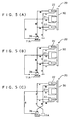
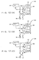
- the operation process of the injection molding unit 300 is shown in Fig. 17 (A) to (C).
- the slide die 10J of the stationary die 10A is at a retracted position relative to the cavity 10C as in Fig. 17(A)
- the molten resin is injected into the cavity 10C by the injection unit 1A as shown in Fig. 17(B).
- the slide die 10J is advanced to the cavity 10C by driving the molding die drive unit 120.
- the injection unit 1A advances so that a nozzle portion thereof follows the slide die 10J.
- Fig. 18 is a cross section showing primary portion of the injection molding unit 400 having the molding die drive unit 120 installed therein.
- the injection molding unit 400 shown in Fig. 18 has the same basic structure as the injection molding unit 300 shown in Fig. 18 and the operation step thereof is different.
- Fig. 18 (A) to (C) The operation process of the injection molding unit 400 is shown in Fig. 18 (A) to (C).
- the molten resin is injected into the cavity 10C by the injection unit 1A when the slide die 10J of the stationary die 10A is advanced to the cavity 10C being spaced apart at a predetermined gap.
- molten resin having expansibility such as resin added with foaming agent and resin including glass fiber is injected into the cavity 10C.
- nozzle portion of the injection unit 1A is refracted from the die 10E and the slide die 10J is refracted from the cavity 10C by driving the molding die drive unit 120 as shown in Fig. 18(C).
- the sub cylinder unit 22 is not shown in Fig. 17 and Fig. 18.
- the molten resin may be loaded into the cavity 10C while advancing the movable die 10B and the movable die 10B may be retracted by the molding die driving device 20 to conduct injection expansion molding thereafter.
- the molten resin may be loaded into the cavity 10C while retracting the slide die 10F and the slide die 10F may be advanced thereafter to conduct the injection compression molding.
- any one of following (1) to (5) may be adopted for the molding method of the present invention:
- any molding method can be used as long as at least a portion of the movable die and the stationary die are relatively moved to freely contract and extend the die interval during molding process in molding the molten resin.
- the present invention can be applied to any molding method having a step of injecting while narrowing and enlarging the gap, applying compressive force to the molten resin, and enlarging and contracting the gap after initiating the injection.
- a separate tank containing hydraulic fluid may be independently provided as well as the hydraulic tank 11A and the hydraulic fluid contained in the tank may be fed to the main cylinder unit 21.
- the molding die drive unit, the molding unit having the molding die drive unit installed therein and the molding method using the molding unit according to the present invention is useful for injection molding, injection compression molding, press molding, large blow gas-injection molding, multi-layered molding, foam molding and expansion molding of glass-fiber containing resin.
- the present invention is suitable for molding in which at least a portion of the die is advanced and refracted to change the cavity volume provided in the die for compressing or expanding (enlarging volume) the resin in the die.
Landscapes
- Engineering & Computer Science (AREA)
- Manufacturing & Machinery (AREA)
- Mechanical Engineering (AREA)
- Injection Moulding Of Plastics Or The Like (AREA)
- Moulds For Moulding Plastics Or The Like (AREA)
- Casting Or Compression Moulding Of Plastics Or The Like (AREA)
Applications Claiming Priority (5)
| Application Number | Priority Date | Filing Date | Title |
|---|---|---|---|
| JP11497398 | 1998-04-24 | ||
| JP11497398 | 1998-04-24 | ||
| JP8905699 | 1999-03-30 | ||
| JP08905699A JP4146026B2 (ja) | 1998-04-24 | 1999-03-30 | 成形装置及び成形方法 |
| PCT/JP1999/002111 WO1999055509A1 (fr) | 1998-04-24 | 1999-04-21 | Dispositif d'entrainement de moule metallique pour le moulage, dispositif de maintien, et procede de maintien |
Publications (2)
| Publication Number | Publication Date |
|---|---|
| EP0999023A1 true EP0999023A1 (fr) | 2000-05-10 |
| EP0999023A4 EP0999023A4 (fr) | 2002-10-16 |
Family
ID=26430495
Family Applications (1)
| Application Number | Title | Priority Date | Filing Date |
|---|---|---|---|
| EP99917072A Withdrawn EP0999023A4 (fr) | 1998-04-24 | 1999-04-21 | Dispositif d'entrainement de moule metallique pour le moulage, dispositif de maintien, et procede de maintien |
Country Status (5)
| Country | Link |
|---|---|
| US (1) | US6440351B1 (fr) |
| EP (1) | EP0999023A4 (fr) |
| JP (1) | JP4146026B2 (fr) |
| CA (1) | CA2295121A1 (fr) |
| WO (1) | WO1999055509A1 (fr) |
Cited By (9)
| Publication number | Priority date | Publication date | Assignee | Title |
|---|---|---|---|---|
| WO2004024416A1 (fr) * | 2002-09-10 | 2004-03-25 | Fountain Patents B.V. | Appareil et procede de fabrication de produits a partir d'une masse thermoplastique |
| NL1023365C2 (nl) * | 2003-05-08 | 2004-11-09 | Fountain Patents B V | Werkwijze en inrichting voor het vervaardigen van voertuigonderdelen. |
| NL1027076C2 (nl) * | 2004-09-20 | 2006-03-22 | Ecim Technologies Bv | Inrichting en werkwijze voor het vervaardigen van kunststof producten. |
| WO2006042824A1 (fr) * | 2004-10-20 | 2006-04-27 | Demag Ergotech Gmbh | Procede de fabrication de pieces moulees en matiere plastique renforcee par des fibres longues |
| NL1027912C2 (nl) * | 2004-12-28 | 2006-07-03 | Ecim Technologies Bv | Matrijs en werkwijze voor de vorming van producten. |
| WO2006131763A1 (fr) * | 2005-06-06 | 2006-12-14 | Im-Pak Technologies Limited | Appareil de moulage par injection / compression |
| WO2007039766A1 (fr) * | 2005-10-03 | 2007-04-12 | Im-Pak Technologies Limited | Moulage par injection-compression par choc |
| WO2008084230A2 (fr) | 2007-01-12 | 2008-07-17 | Peter Reginald Clarke | Moule à injection et procédé de moulage par injection |
| WO2016034990A1 (fr) * | 2014-09-02 | 2016-03-10 | Plasdan - Automação E Sistemas, Lda. | Unité modulaire pour moulage par injection-compression |
Families Citing this family (19)
| Publication number | Priority date | Publication date | Assignee | Title |
|---|---|---|---|---|
| MXPA03006664A (es) * | 2001-01-26 | 2004-10-15 | Coraltech Ltd | Molde y metodo para moldeo por inyeccion-compresion. |
| JP4619561B2 (ja) * | 2001-03-27 | 2011-01-26 | 東芝機械株式会社 | 射出発泡成形機の型開閉装置 |
| US7186102B2 (en) * | 2001-04-26 | 2007-03-06 | Strandex Corporation | Apparatus and method for low-density cellular wood plastic composites |
| JP3942945B2 (ja) * | 2001-05-31 | 2007-07-11 | 株式会社神戸製鋼所 | 射出圧縮成形装置、射出圧縮成形方法およびその方法による射出圧縮成形品 |
| JP4377377B2 (ja) * | 2003-05-22 | 2009-12-02 | 住友重機械工業株式会社 | 成形方法、成形品及び成形機 |
| US8179808B2 (en) * | 2003-10-31 | 2012-05-15 | Brocade Communication Systems, Inc. | Network path tracing method |
| EP1757427A3 (fr) * | 2005-08-27 | 2007-05-02 | Behr GmbH & Co. KG | Procédé de moulage par injection compression |
| US20070063386A1 (en) * | 2005-09-01 | 2007-03-22 | Seaver Richard T | Mold tool having movable core |
| KR100801189B1 (ko) * | 2006-04-12 | 2008-02-04 | (주) 민성정밀 | 박판 성형을 위한 사출성형장치 |
| JP4671294B2 (ja) * | 2006-10-30 | 2011-04-13 | 株式会社名機製作所 | 射出成形機の射出圧縮成形方法 |
| ITTV20060198A1 (it) * | 2006-11-03 | 2008-05-04 | Inglass Spa | Struttura portante ausiliaria per presse e pressa per la produzione di manufatti in materiale plastico provvista di tale struttura. |
| US7931845B2 (en) * | 2007-05-21 | 2011-04-26 | O & D Manufacturing | Gravity injection of molding material for compression molding and related methods |
| EP2052835A1 (fr) * | 2007-10-26 | 2009-04-29 | Rieter Technologies AG | Procédé et appareil de moulage par injection |
| FR2933328B1 (fr) * | 2008-07-01 | 2016-08-26 | Aplix Sa | Dispositif formant moule pour fabriquer un objet moule comportant un champ de crochets |
| US9193104B2 (en) * | 2008-07-01 | 2015-11-24 | Aplix | Injection-moulded article comprising a field of hooks obtained by moulding |
| DK2346664T3 (da) * | 2008-09-15 | 2013-04-02 | Momexx B V | Apparat og fremgangsmåde til styring af injektionskompressionsstøbning |
| JP5324377B2 (ja) | 2009-09-30 | 2013-10-23 | 三菱重工プラスチックテクノロジー株式会社 | 射出発泡成形機 |
| JP6608168B2 (ja) * | 2014-10-28 | 2019-11-20 | 東芝機械株式会社 | 開閉装置および成形装置 |
| JP7032188B2 (ja) * | 2017-03-31 | 2022-03-08 | 住友重機械工業株式会社 | 射出成形機 |
Family Cites Families (16)
| Publication number | Priority date | Publication date | Assignee | Title |
|---|---|---|---|---|
| DE1243379B (de) * | 1961-04-26 | 1967-06-29 | Spezialmaschinen Co Deutsche | Vorrichtung zum Steuern einer Spritzgiessmaschine zur Herstellung von Gegenstaenden aus Kunststoff oder Gummi |
| DE2416694A1 (de) * | 1974-04-05 | 1975-10-23 | Schloemann Siemag Ag | Vorrichtung zur herstellung von formteilen aus kunststoff |
| DE2852516C2 (de) * | 1978-12-05 | 1987-01-02 | Krauss-Maffei AG, 8000 München | Formschließvorrichtung für eine Spritzgießmaschine |
| JPS5795429A (en) | 1980-12-05 | 1982-06-14 | Hitachi Ltd | Mold for injection and compression molding |
| JPS5822139A (ja) * | 1981-08-03 | 1983-02-09 | Toshiba Ii M I Kk | デイスクの製造装置 |
| JPS60122128A (ja) | 1983-12-06 | 1985-06-29 | Ricoh Co Ltd | 射出圧縮成形型 |
| JPS63312125A (ja) * | 1987-06-15 | 1988-12-20 | Kobe Steel Ltd | 圧縮成形プレス |
| JPH07110509B2 (ja) * | 1992-02-05 | 1995-11-29 | 日精樹脂工業株式会社 | 射出成形機の型締装置 |
| JP2880086B2 (ja) | 1993-09-14 | 1999-04-05 | 出光石油化学株式会社 | 射出成形機の圧縮装置および射出圧縮成形機 |
| JP2653754B2 (ja) * | 1993-11-08 | 1997-09-17 | 日精樹脂工業株式会社 | 成形機の型開閉制御方法 |
| JPH07214567A (ja) * | 1994-01-31 | 1995-08-15 | Meiki Co Ltd | 型締装置 |
| AT404640B (de) * | 1994-02-18 | 1999-01-25 | Engel Gmbh Maschbau | Verfahren zum betätigen der schliesseinrichtung einer zweiplatten-spritzgiessmaschine |
| JPH08267212A (ja) * | 1995-03-31 | 1996-10-15 | Ube Ind Ltd | 成形機の型締装置 |
| JPH0938985A (ja) * | 1995-07-25 | 1997-02-10 | Toshiba Mach Co Ltd | 型開閉装置 |
| US6010656A (en) * | 1996-02-16 | 2000-01-04 | Idemitsu Petrochemical Co., Ltd. | Method of forming a light-weight, fiber-reinforced thermoplastic resin product and a light-weight molded product |
| JP3262215B2 (ja) * | 1997-08-18 | 2002-03-04 | 日精樹脂工業株式会社 | 直圧式型締装置の型締方法 |
-
1999
- 1999-03-30 JP JP08905699A patent/JP4146026B2/ja not_active Expired - Fee Related
- 1999-04-21 CA CA002295121A patent/CA2295121A1/fr not_active Abandoned
- 1999-04-21 EP EP99917072A patent/EP0999023A4/fr not_active Withdrawn
- 1999-04-21 US US09/446,670 patent/US6440351B1/en not_active Expired - Fee Related
- 1999-04-21 WO PCT/JP1999/002111 patent/WO1999055509A1/fr not_active Ceased
Cited By (28)
| Publication number | Priority date | Publication date | Assignee | Title |
|---|---|---|---|---|
| EP2033761A1 (fr) * | 2002-09-10 | 2009-03-11 | ECIM Technologies B.V. | Appareil et procédé de fabrication de produits à partir d'une masse thermoplastique |
| US8360769B2 (en) | 2002-09-10 | 2013-01-29 | Ecim Technologies B.V. | Apparatus for manufacturing products from a thermoplastic mass |
| US7891970B2 (en) | 2002-09-10 | 2011-02-22 | Ecim Technologies B.V. | Apparatus and method for manufacturing products from a thermoplastic mass |
| WO2004024416A1 (fr) * | 2002-09-10 | 2004-03-25 | Fountain Patents B.V. | Appareil et procede de fabrication de produits a partir d'une masse thermoplastique |
| RU2351699C2 (ru) * | 2003-05-08 | 2009-04-10 | Эсим Текнолоджиз Б.В. | Способ изготовления деталей средств передвижения |
| WO2004099480A3 (fr) * | 2003-05-08 | 2005-01-20 | Fountain Patents B V | Procede et appareil de fabrication de parties de vehicules |
| CN1820102B (zh) * | 2003-05-08 | 2010-06-16 | Ecim科技公司 | 用于制造车辆部件的方法和装置 |
| US7833462B2 (en) | 2003-05-08 | 2010-11-16 | Ecim Technologies B.V. | Method and apparatus for manufacturing vehicle parts |
| WO2004099480A2 (fr) | 2003-05-08 | 2004-11-18 | Ecim Technologies B.V. | Procede et appareil de fabrication de parties de vehicules |
| NL1023365C2 (nl) * | 2003-05-08 | 2004-11-09 | Fountain Patents B V | Werkwijze en inrichting voor het vervaardigen van voertuigonderdelen. |
| EP2309044A3 (fr) * | 2003-05-08 | 2011-05-25 | ECIM Technologies B.V. | Procédé et appareil pour la fabrication de pièces de véhicule |
| EP2278053A3 (fr) * | 2003-05-08 | 2011-05-25 | ECIM Technologies B.V. | Procédé et appareil pour la fabrication de pièces de véhicule |
| NL1027076C2 (nl) * | 2004-09-20 | 2006-03-22 | Ecim Technologies Bv | Inrichting en werkwijze voor het vervaardigen van kunststof producten. |
| WO2006033571A1 (fr) * | 2004-09-20 | 2006-03-30 | Ecim Technologies B.V. | Appareil et procédé de fabrication de produits plastiques |
| RU2387539C2 (ru) * | 2004-09-20 | 2010-04-27 | Эсим Текнолоджиз Б.В. | Устройство и способ производства пластмассовых изделий |
| WO2006042824A1 (fr) * | 2004-10-20 | 2006-04-27 | Demag Ergotech Gmbh | Procede de fabrication de pieces moulees en matiere plastique renforcee par des fibres longues |
| WO2006071111A1 (fr) * | 2004-12-28 | 2006-07-06 | Ecim Technologies B.V. | Moule et procede pour former des produits |
| US7771645B2 (en) | 2004-12-28 | 2010-08-10 | Ecim Technologies B.V. | Mold and method for forming products |
| NL1027912C2 (nl) * | 2004-12-28 | 2006-07-03 | Ecim Technologies Bv | Matrijs en werkwijze voor de vorming van producten. |
| US7563093B2 (en) | 2005-06-06 | 2009-07-21 | Im-Pak Technologies Limited | Injection compression moulding apparatus |
| WO2006131763A1 (fr) * | 2005-06-06 | 2006-12-14 | Im-Pak Technologies Limited | Appareil de moulage par injection / compression |
| WO2007039766A1 (fr) * | 2005-10-03 | 2007-04-12 | Im-Pak Technologies Limited | Moulage par injection-compression par choc |
| CN101674924A (zh) * | 2007-01-12 | 2010-03-17 | 彼得·雷金纳德·克拉克 | 注射模具和注射模制方法 |
| WO2008084230A3 (fr) * | 2007-01-12 | 2009-02-26 | Peter Reginald Clarke | Moule à injection et procédé de moulage par injection |
| WO2008084230A2 (fr) | 2007-01-12 | 2008-07-17 | Peter Reginald Clarke | Moule à injection et procédé de moulage par injection |
| US8114332B2 (en) | 2007-01-12 | 2012-02-14 | Peter Reginald Clarke | Injection moulding method |
| US8419418B2 (en) | 2007-01-12 | 2013-04-16 | Peter Reginald Clark | Injection mould having a varying volume mould cavity |
| WO2016034990A1 (fr) * | 2014-09-02 | 2016-03-10 | Plasdan - Automação E Sistemas, Lda. | Unité modulaire pour moulage par injection-compression |
Also Published As
| Publication number | Publication date |
|---|---|
| JP2000006213A (ja) | 2000-01-11 |
| US6440351B1 (en) | 2002-08-27 |
| EP0999023A4 (fr) | 2002-10-16 |
| JP4146026B2 (ja) | 2008-09-03 |
| CA2295121A1 (fr) | 1999-11-04 |
| WO1999055509A1 (fr) | 1999-11-04 |
Similar Documents
| Publication | Publication Date | Title |
|---|---|---|
| US6440351B1 (en) | Molding die drive unit, molding unit and molding method | |
| EP0389646B1 (fr) | Procede et appareil de moulage par injection | |
| US8419418B2 (en) | Injection mould having a varying volume mould cavity | |
| JP4377377B2 (ja) | 成形方法、成形品及び成形機 | |
| KR20060033018A (ko) | 성형방법, 성형용 금형, 성형품 및 성형기 | |
| US5728410A (en) | System for injection molding of plastic article utilizing a variable volume spill cavity | |
| KR20030043699A (ko) | 금형 장치에 의한 수지 성형품의 성형 방법, 금형 장치,수지 성형품, 금형 장치를 갖는 성형기 | |
| US5139714A (en) | Process for injection molding a hollow plastic article | |
| EP0823871B1 (fr) | Procede et systeme de moulage par injection faisant appel a une cavite de coulage a volume variable et produit fabrique selon ce procede | |
| EP0664196B1 (fr) | Procédé et dispositif de moulage d'articles en plastique de densités différentes | |
| HK1006210B (en) | Method of injection molding a thermoplastic resin and a mold for injection molding | |
| JP3827333B2 (ja) | ガス射出成形方法およびその金型 | |
| US20200114560A1 (en) | Molding machine | |
| US4545756A (en) | Hydraulic clamping apparatus for an injection molding machine | |
| EP0035916B1 (fr) | Dispositif de changement pour machines à injection | |
| EP3782789B1 (fr) | Procédé de moulage par injection de mousse | |
| EP0884156B1 (fr) | Procédé de fabrication par moulage d'articles creux en résine thermoplastique | |
| JPH0924520A (ja) | 型締装置 | |
| JPH05220786A (ja) | 射出成形金型 | |
| JP3273696B2 (ja) | ガス注入射出成形方法およびその装置 | |
| US20060240142A1 (en) | Clamping apparatus for injection molding machine | |
| CN121105335A (zh) | 一种具有辅助微开模与封胶结构的注塑装置 | |
| JP2732774B2 (ja) | 型締シリンダのピストン後退量設定装置 | |
| JPH1128738A (ja) | 繊維含有樹脂のガス注入成形方法 | |
| JPH01114411A (ja) | 射出圧縮成形方法及び装置 |
Legal Events
| Date | Code | Title | Description |
|---|---|---|---|
| PUAI | Public reference made under article 153(3) epc to a published international application that has entered the european phase |
Free format text: ORIGINAL CODE: 0009012 |
|
| 17P | Request for examination filed |
Effective date: 20000124 |
|
| AK | Designated contracting states |
Kind code of ref document: A1 Designated state(s): DE FR IT |
|
| A4 | Supplementary search report drawn up and despatched |
Effective date: 20020902 |
|
| AK | Designated contracting states |
Kind code of ref document: A4 Designated state(s): DE FR IT |
|
| RIC1 | Information provided on ipc code assigned before grant |
Free format text: 7B 29C 33/24 A, 7B 29C 45/67 B, 7B 29C 43/36 B, 7B 29C 45/56 B |
|
| RAP1 | Party data changed (applicant data changed or rights of an application transferred) |
Owner name: IDEMITSU KOSAN CO., LTD. |
|
| RAP1 | Party data changed (applicant data changed or rights of an application transferred) |
Owner name: PRIME POLYMER CO., LTD. |
|
| 17Q | First examination report despatched |
Effective date: 20070809 |
|
| STAA | Information on the status of an ep patent application or granted ep patent |
Free format text: STATUS: THE APPLICATION IS DEEMED TO BE WITHDRAWN |
|
| 18D | Application deemed to be withdrawn |
Effective date: 20071219 |