EP0999613B1 - Leiterplattensteckverbinder bestehend aus Stecker und Gegenstück - Google Patents
Leiterplattensteckverbinder bestehend aus Stecker und Gegenstück Download PDFInfo
- Publication number
- EP0999613B1 EP0999613B1 EP99402711A EP99402711A EP0999613B1 EP 0999613 B1 EP0999613 B1 EP 0999613B1 EP 99402711 A EP99402711 A EP 99402711A EP 99402711 A EP99402711 A EP 99402711A EP 0999613 B1 EP0999613 B1 EP 0999613B1
- Authority
- EP
- European Patent Office
- Prior art keywords
- plug
- socket
- contacts
- edge
- board
- Prior art date
- Legal status (The legal status is an assumption and is not a legal conclusion. Google has not performed a legal analysis and makes no representation as to the accuracy of the status listed.)
- Expired - Lifetime
Links
- 238000003780 insertion Methods 0.000 claims abstract description 24
- 230000037431 insertion Effects 0.000 claims abstract description 24
- 230000000630 rising effect Effects 0.000 claims description 4
- 230000000295 complement effect Effects 0.000 claims description 3
- 239000004020 conductor Substances 0.000 abstract description 2
- 238000003032 molecular docking Methods 0.000 description 4
- 240000000966 Allium tricoccum Species 0.000 description 2
- 238000005452 bending Methods 0.000 description 2
- 230000015556 catabolic process Effects 0.000 description 2
- 238000004140 cleaning Methods 0.000 description 2
- 238000006731 degradation reaction Methods 0.000 description 2
- 230000000694 effects Effects 0.000 description 2
- 241000446313 Lamella Species 0.000 description 1
- 239000003082 abrasive agent Substances 0.000 description 1
- 230000001174 ascending effect Effects 0.000 description 1
- 230000009286 beneficial effect Effects 0.000 description 1
- 230000006378 damage Effects 0.000 description 1
- 238000012986 modification Methods 0.000 description 1
- 230000004048 modification Effects 0.000 description 1
Images


Classifications
-
- H—ELECTRICITY
- H01—ELECTRIC ELEMENTS
- H01R—ELECTRICALLY-CONDUCTIVE CONNECTIONS; STRUCTURAL ASSOCIATIONS OF A PLURALITY OF MUTUALLY-INSULATED ELECTRICAL CONNECTING ELEMENTS; COUPLING DEVICES; CURRENT COLLECTORS
- H01R12/00—Structural associations of a plurality of mutually-insulated electrical connecting elements, specially adapted for printed circuits, e.g. printed circuit boards [PCB], flat or ribbon cables, or like generally planar structures, e.g. terminal strips, terminal blocks; Coupling devices specially adapted for printed circuits, flat or ribbon cables, or like generally planar structures; Terminals specially adapted for contact with, or insertion into, printed circuits, flat or ribbon cables, or like generally planar structures
- H01R12/70—Coupling devices
- H01R12/71—Coupling devices for rigid printing circuits or like structures
- H01R12/72—Coupling devices for rigid printing circuits or like structures coupling with the edge of the rigid printed circuits or like structures
- H01R12/721—Coupling devices for rigid printing circuits or like structures coupling with the edge of the rigid printed circuits or like structures cooperating directly with the edge of the rigid printed circuits
-
- H—ELECTRICITY
- H01—ELECTRIC ELEMENTS
- H01R—ELECTRICALLY-CONDUCTIVE CONNECTIONS; STRUCTURAL ASSOCIATIONS OF A PLURALITY OF MUTUALLY-INSULATED ELECTRICAL CONNECTING ELEMENTS; COUPLING DEVICES; CURRENT COLLECTORS
- H01R13/00—Details of coupling devices of the kinds covered by groups H01R12/70 or H01R24/00 - H01R33/00
- H01R13/02—Contact members
- H01R13/26—Pin or blade contacts for sliding co-operation on one side only
-
- H—ELECTRICITY
- H01—ELECTRIC ELEMENTS
- H01R—ELECTRICALLY-CONDUCTIVE CONNECTIONS; STRUCTURAL ASSOCIATIONS OF A PLURALITY OF MUTUALLY-INSULATED ELECTRICAL CONNECTING ELEMENTS; COUPLING DEVICES; CURRENT COLLECTORS
- H01R2201/00—Connectors or connections adapted for particular applications
- H01R2201/16—Connectors or connections adapted for particular applications for telephony
Definitions
- the present invention relates to a socket connection intended to come and engage on the edge of a printed circuit board with contacts intended to take elastic support on the part and on the other side of the card to establish a direct connection with conductive connection pads of this menu.
- the invention relates in particular to a socket connection of an accessory to be connected directly to the circuit board of a mobile phone, this phone mobile not having on its connector base input / output but a printed circuit (usually soldered to the input / output connector) directly accessible for connection to an external accessory or sheet.
- document EP 0 036 933 describes a connector comprising a base without contacts intended to be fixed on the edge of the printed circuit board, this base having an opening for receiving a plug comprising two parallel rows of contact elements spaced by a recess, and intended to support elastically on either side of the map to establish a direct connection with beaches card connection conductors, after insertion of the plug in the opening of the base, elements elastic being provided to be compressed by the base and thus support the contact elements on the pads contact card.
- the major technical problem posed with this type of application relates to degradation, or even destruction of the pins by the strongly edges abrasives of the printed circuit at the time of insertion, which has the effect of considerably limiting the number of connection / disconnection operations.
- a second problem is to ensure a pressure of sufficient contact between the accessory contacts and the connection areas of the printed circuit.
- the object of the invention is precisely to solve the two problems above.
- the plug contacts do not rub on the outer edges of the map, when the engagement of the plug in the socket.
- the friction on the connection pads is very limited.
- the contacts are supported elastically on the connection areas of the card only when the plug is almost completely engaged on the edge of the card, without degradation of contacts when inserting the plug into the socket.
- the base and the plug include means complementary to lock them together at the end of stroke for inserting the plug into the socket.
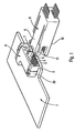
- connection socket intended to engage on the edge 2 of a printed circuit board 1 has contacts 3, 4 intended to bear elastically on either side of card 1 to establish a direct connection with conductive pads of connection 5 of this card.
- the socket comprises a base 6 devoid of contacts intended to be fixed on the printed circuit board 1 by lugs hook 20 (fittings).
- This base 6 includes a opening 7 to receive a card 8 comprising two parallel rows of elastic contacts 3, 4 intended to be supported on the conductive pads 5, after insertion of plug 8 into opening 7 of base 6.
- one 3 rows of contacts is carried by a first flexible part 9 of the plug 8 which can engage in the opening 7 of the base 6.
- the other row of contacts 4 is carried by a second part 10 of sheet 8 separated from the first part 9 by a recess 11 and can engage under edge 2 of the circuit board printed 1.
- the base 6 and the plug 8 include additional resources for lock together at the end of the insertion stroke of plug 8 in socket 6.
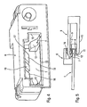
- the means to move plug 8 upwards when insertion in the base 6 include two ramps risers 12 located inside the base 6 and protruding above a plane passing through the edge lower 13 of the opening 7 for inserting the plug 8 in the base 6. These ramps 12 cooperate with the end 14a of two guide beams 14 arranged on either side of flexible part 9 of sheet 8 to move it up.
- Figure 4 also shows that the ramps 12 are located at a certain distance d from the edge lower 13 of the opening 7 for inserting the plug 8 in base 6.
- the two ramps 12 are each located near a side edge 15 of the opening 7 for introducing sheet 8.
- Means for bending down the flexible part 9 of the plug 8 during its insertion in the base 6 include two descending ramps 16 (see Figure 4) located inside the base 6 and protruding below a plane passing through the edge upper 17 of the opening 7 for inserting the plug 8. These ramps 16 cooperate with the end 9a of the flexible part 9 of the plug to bend it towards the bottom.
- Additional means to lock together the base 6 and the plug 8 include a spout latching 18 (see Figures 2 and 3) formed on the upper side and near the end 9a of the part flexible 9 of the plug 8 cooperating with a lamella flexible 19 (see FIG. 4) formed in the base 6.
- connection socket that we have just described works as follows:
- the lower row 4 of contacts rests elastically on the ranges of connection 5 provided on the underside of the card.
- the spout 18 located at the front of the flexible part 9 of the plug 8 snaps onto the end of the strip 19 located inside the base 6, thereby locking the plug 8 of the base 6.
Landscapes
- Coupling Device And Connection With Printed Circuit (AREA)
- Details Of Connecting Devices For Male And Female Coupling (AREA)
- Shaping Of Tube Ends By Bending Or Straightening (AREA)
- Addition Polymer Or Copolymer, Post-Treatments, Or Chemical Modifications (AREA)
Claims (8)
- Steckverbinder für den Eingriff auf der Kante (2) einer Leiterplatte (1), der Kontakte (3, 4) aufweist, die elastisch auf der einen und anderen Seite der Platte (1) aufliegen und einen direkten Kontakt mit den Verbindungskontaktflächen (5) der Platte (1) herstellen, wobei der Steckverbinder eine Buchse (6) mit Kontakten und Einrichtungen für die Befestigung auf der Leiterplatte (1) und eine Öffnung (7) aufweist, um einen Gegenstecker (8) aufzunehmen, der zwei parallele Reihen von elastischen Kontakten (3, 4) aufweist, die nach der Einführung des Gegensteckers (8) in die Öffnung (7) der Buchse (6) auf den Kontaktflächen (5) aufliegen, wobei eine Reihe (3) der Kontaktreihen durch einen ersten Abschnitt (9) des Gegensteckers (8) getragen wird und die andere Kontaktreihe (4) durch den zweiten Abschnitt (10) des Gegensteckers getragen wird, der von dem ersten Abschnitt (9) durch eine Aussparung (11) getrennt ist und der unter die Kante (2) der Leiterplatte (1) eingreifen kann,
dadurch gekennzeichnet, daß
der erste Abschnitt (9) des Gegensteckers (8) biegbar ist und das Innere der Buchse (6) und der Gegenstecker (8) aufweisen:Einrichtungen (14, 15), die zusammenwirken und den Gegenstecker (8) bei seiner Einführung in die Buchse (6) führen, ohne daß die Kontaktreihen (3, 4) die Verbindungsflächen (5) der Platte berühren,aufsteigende Rampen (12), die im Inneren der Buchse (6) angeordnet sind und über die Ebene überstehen, die durch eine untere Kante (13) der Einführungsöffnung (7) des Gegenstekkers (8) verläuft, wobei diese Rampen (12) mit einem Ende (14a) des Gegensteckers zusammenwirken und den Gegenstecker (8) nach oben verschieben, wodurch das Ankoppeln der von dem zweiten Abschnitt (10) des Gegensteckers getragenen Kontaktreihe (4) an die unter der Kante (2) der Platte gelegenen Verbindungsflächen (5) am Ende der Einführung des Gegensteckers in die Buchse ermöglicht wird,mindestens eine absteigende Rampe (16), die im Inneren der Buchse (6) gelegen ist und unter eine Ebene vorspringt, die durch eine obere Kante (17) der Einführungsöffnung (7) des Gegensteckers (8) verläuft, wobei diese Rampe (16) mit einem Ende (9a) des ersten biegsamen Abschnitts (9) zusammenwirkt und diesen nach unten biegt und somit ein Ankoppeln der durch den ersten Abschnitt (9) getragenen Kontaktreihe (3) an die auf der Kante (2) der Platte gelegenen Kontaktflächen (5) beim Einführungsende des Gegensteckers in die Buchse ermöglicht. - Steckverbinder nach Anspruch 1, dadurch gekennzeichnet, daß die Buchse (6) und der Gegenstecker (8) komplementäre Einrichtungen (18, 19) aufweisen, die sich miteinander am Ende der Einführung des Gegensteckers (8) in die Buchse (6) verriegeln.
- Steckverbinder nach Anspruch 2, dadurch gekennzeichnet, daß die komplementären Einrichtungen für die Verriegelung der Buchse (6) mit dem Gegenstecker (8) einen Rastvorsprung (18) aufweisen, der auf der Oberseite und in der Nähe des Endes (9a) des flexiblen Abschnitts (9) des Gegensteckers (8) angeordnet ist, der mit einer in der Buchse (6) angebrachten biegsamen Lamelle (19) zusammenwirkt.
- Steckverbinder nach einem der Ansprüche 1 bis 3, dadurch gekennzeichnet, daß die aufsteigenden Rampen (12) in einem gewissen Abstand (d) von der unteren Kante (13) der Einführungsöffnung (7) des Gegensteckers (8) in die Buchse (6) angeordnet sind.
- Steckverbinder nach Anspruch 4, dadurch gekennzeichnet, daß die Form der Rampen (12, 16) derart ausgewählt wird, daß die Kontakte (3, 4) am Ende der Einführung des Gegensteckers in die Buchse einen kurzen Weg auf den Verbindungsflächen der Karte (1) gleiten.
- Steckverbinder nach einem der Ansprüche 1 bis 5, dadurch gekennzeichnet, daß zwei aufsteigende Rampen (12) vorgesehen sind, die jeweils in der Nähe einer seitlichen Kante der Einführungsöffnung (7) des Gegensteckers (8) angeordnet sind.
- Steckverbinder nach einem der Ansprüche 1 bis 6, dadurch gekennzeichnet, daß der biegsame Abschnitt (9) des Gegensteckers (8) zwischen zwei seitlichen Führungsträgern des Gegensteckers (8) angeordnet sind.
- Steckverbinder nach einem der Ansprüche 1 bis 7, dadurch gekennzeichnet, daß die Einrichtungen für die Befestigung der Buchse (6) auf der Karte (1) Befestigungsklammern (20) aurweisen.
Applications Claiming Priority (2)
| Application Number | Priority Date | Filing Date | Title |
|---|---|---|---|
| FR9814028 | 1998-11-06 | ||
| FR9814028A FR2785723B1 (fr) | 1998-11-06 | 1998-11-06 | Prise de connexion sur circuit imprime, comprenant une fiche et une embase |
Publications (2)
| Publication Number | Publication Date |
|---|---|
| EP0999613A1 EP0999613A1 (de) | 2000-05-10 |
| EP0999613B1 true EP0999613B1 (de) | 2003-03-05 |
Family
ID=9532486
Family Applications (1)
| Application Number | Title | Priority Date | Filing Date |
|---|---|---|---|
| EP99402711A Expired - Lifetime EP0999613B1 (de) | 1998-11-06 | 1999-10-29 | Leiterplattensteckverbinder bestehend aus Stecker und Gegenstück |
Country Status (9)
| Country | Link |
|---|---|
| US (1) | US6234822B1 (de) |
| EP (1) | EP0999613B1 (de) |
| JP (1) | JP2000188144A (de) |
| CN (1) | CN1253397A (de) |
| AT (1) | ATE233963T1 (de) |
| CA (1) | CA2288414A1 (de) |
| DE (1) | DE69905681T2 (de) |
| FR (1) | FR2785723B1 (de) |
| SG (1) | SG75992A1 (de) |
Families Citing this family (9)
| Publication number | Priority date | Publication date | Assignee | Title |
|---|---|---|---|---|
| US6346012B1 (en) * | 1998-08-15 | 2002-02-12 | Delta Electronics, Inc. | Locking cartridge for conveniently locking very thin connector with near-zero inductance onto PC board |
| JP2002184539A (ja) | 2000-12-14 | 2002-06-28 | Auto Network Gijutsu Kenkyusho:Kk | コネクタ |
| JP4841756B2 (ja) * | 2001-06-08 | 2011-12-21 | 日本圧着端子製造株式会社 | コンタクトとこれを装着した電気コネクタ |
| CN100350312C (zh) * | 2004-11-18 | 2007-11-21 | 友达光电股份有限公司 | 平面显示器以及其背光模块 |
| JP2006302651A (ja) * | 2005-04-20 | 2006-11-02 | Sumitomo Electric Ind Ltd | コネクタ |
| US8496486B2 (en) * | 2010-07-19 | 2013-07-30 | Tyco Electronics Corporation | Transceiver assembly |
| DE102011005479A1 (de) * | 2011-03-14 | 2012-09-20 | Robert Bosch Gmbh | Direktsteckelement mit zwei Federbereichen |
| US9917387B2 (en) * | 2015-06-10 | 2018-03-13 | Osram Gmbh | Connector for lighting devices, corresponding accessory and method |
| CN112421720A (zh) * | 2020-11-10 | 2021-02-26 | 东莞市爱客德电子科技有限公司 | 一种充电坞及充电坞电路 |
Family Cites Families (4)
| Publication number | Priority date | Publication date | Assignee | Title |
|---|---|---|---|---|
| EP0036933A3 (de) * | 1980-03-28 | 1981-12-02 | Bohdan Ulrich | Steckverbinder und Verwendung desselben zur Herstellung einer lösbaren elektrischen Verbindung |
| FR2604804B1 (fr) | 1986-10-02 | 1989-12-29 | Francelco Sa | Systeme a lecture de cartes d'identification a contacts electriques |
| US4863395A (en) * | 1989-01-17 | 1989-09-05 | Robert Babuka | Zero insertion force connector with component card |
| DE8907845U1 (de) * | 1989-06-27 | 1989-08-24 | Siemens AG, 1000 Berlin und 8000 München | Andruckstellverbinder |
-
1998
- 1998-11-06 FR FR9814028A patent/FR2785723B1/fr not_active Expired - Fee Related
-
1999
- 1999-10-29 AT AT99402711T patent/ATE233963T1/de not_active IP Right Cessation
- 1999-10-29 DE DE69905681T patent/DE69905681T2/de not_active Expired - Fee Related
- 1999-10-29 EP EP99402711A patent/EP0999613B1/de not_active Expired - Lifetime
- 1999-11-01 SG SG1999005407A patent/SG75992A1/en unknown
- 1999-11-03 CA CA002288414A patent/CA2288414A1/en not_active Abandoned
- 1999-11-05 US US09/435,263 patent/US6234822B1/en not_active Expired - Fee Related
- 1999-11-05 CN CN99123438A patent/CN1253397A/zh active Pending
- 1999-11-08 JP JP11317451A patent/JP2000188144A/ja active Pending
Also Published As
| Publication number | Publication date |
|---|---|
| DE69905681T2 (de) | 2003-11-06 |
| US6234822B1 (en) | 2001-05-22 |
| FR2785723A1 (fr) | 2000-05-12 |
| EP0999613A1 (de) | 2000-05-10 |
| FR2785723B1 (fr) | 2003-05-23 |
| ATE233963T1 (de) | 2003-03-15 |
| CA2288414A1 (en) | 2000-05-06 |
| CN1253397A (zh) | 2000-05-17 |
| JP2000188144A (ja) | 2000-07-04 |
| DE69905681D1 (de) | 2003-04-10 |
| SG75992A1 (en) | 2000-10-24 |
Similar Documents
| Publication | Publication Date | Title |
|---|---|---|
| KR101990508B1 (ko) | 강도가 강화된 플러그커넥터 | |
| KR102149849B1 (ko) | 스프링 부하형 연결 단자 및 전도체 연결 단자 | |
| EP1154527B1 (de) | Verbindungsvorrichtung zur Verbindung zwischen einem Koaxialkabel und einer Leiterplatte | |
| US7147498B1 (en) | Connector for flexible printed circuit | |
| FR2785724A1 (fr) | Connecteur electrique blinde comportant un element de support pour pattes | |
| FR3017253A1 (fr) | Connecteur electrique | |
| CN103943995B (zh) | 基板边缘连接器 | |
| CN102280769A (zh) | 电连接器 | |
| KR19980032023A (ko) | 암형 전기 단자 | |
| JPH0613130A (ja) | 係止可能なケーシング半部を備えた電気的なプラグ結合装置 | |
| EP0999613A1 (de) | Leiterplattensteckverbinder bestehend aus Stecker und Gegenstück | |
| EP3376609B1 (de) | Buchse und verbindungsstruktur für buchse und stecker | |
| CA2242029C (en) | Slimline plug-in connector | |
| CN100561802C (zh) | 连接器 | |
| FR2647602A1 (fr) | Contact femelle | |
| FR2464572A1 (fr) | Perfectionnement aux connexions electriques par clip et languette | |
| US6254400B1 (en) | Connector structure | |
| US5741154A (en) | Electrical connector for flat cable | |
| TWM302800U (en) | Electrical connector | |
| KR102768646B1 (ko) | 커넥터 및 커넥터조립체 | |
| FR2783361A1 (fr) | Ensemble conecteur blinde pouvant etre monte de maniere ferme sur une carte circuit | |
| KR200330184Y1 (ko) | 접지단자 | |
| JP3371248B2 (ja) | ソケットコネクタ及び小型基板接続構造 | |
| EP0674357B1 (de) | Gehäuseteilen von elektrischen Verbindern | |
| CN201191664Y (zh) | 电连接器 |
Legal Events
| Date | Code | Title | Description |
|---|---|---|---|
| PUAI | Public reference made under article 153(3) epc to a published international application that has entered the european phase |
Free format text: ORIGINAL CODE: 0009012 |
|
| AK | Designated contracting states |
Kind code of ref document: A1 Designated state(s): AT BE CH CY DE DK ES FI FR GB GR IE IT LI LU MC NL PT SE |
|
| AX | Request for extension of the european patent |
Free format text: AL;LT;LV;MK;RO;SI |
|
| 17P | Request for examination filed |
Effective date: 20001020 |
|
| AKX | Designation fees paid |
Free format text: AT BE CH CY DE DK ES FI FR GB GR IE IT LI LU MC NL PT SE |
|
| 17Q | First examination report despatched |
Effective date: 20010724 |
|
| GRAG | Despatch of communication of intention to grant |
Free format text: ORIGINAL CODE: EPIDOS AGRA |
|
| GRAG | Despatch of communication of intention to grant |
Free format text: ORIGINAL CODE: EPIDOS AGRA |
|
| GRAH | Despatch of communication of intention to grant a patent |
Free format text: ORIGINAL CODE: EPIDOS IGRA |
|
| GRAH | Despatch of communication of intention to grant a patent |
Free format text: ORIGINAL CODE: EPIDOS IGRA |
|
| RAP1 | Party data changed (applicant data changed or rights of an application transferred) |
Owner name: FCI |
|
| GRAA | (expected) grant |
Free format text: ORIGINAL CODE: 0009210 |
|
| AK | Designated contracting states |
Designated state(s): AT BE CH CY DE DK ES FI FR GB GR IE IT LI LU MC NL PT SE |
|
| PG25 | Lapsed in a contracting state [announced via postgrant information from national office to epo] |
Ref country code: NL Free format text: LAPSE BECAUSE OF FAILURE TO SUBMIT A TRANSLATION OF THE DESCRIPTION OR TO PAY THE FEE WITHIN THE PRESCRIBED TIME-LIMIT Effective date: 20030305 Ref country code: IT Free format text: LAPSE BECAUSE OF FAILURE TO SUBMIT A TRANSLATION OF THE DESCRIPTION OR TO PAY THE FEE WITHIN THE PRESCRIBED TIME-LIMIT;WARNING: LAPSES OF ITALIAN PATENTS WITH EFFECTIVE DATE BEFORE 2007 MAY HAVE OCCURRED AT ANY TIME BEFORE 2007. THE CORRECT EFFECTIVE DATE MAY BE DIFFERENT FROM THE ONE RECORDED. Effective date: 20030305 Ref country code: IE Free format text: LAPSE BECAUSE OF FAILURE TO SUBMIT A TRANSLATION OF THE DESCRIPTION OR TO PAY THE FEE WITHIN THE PRESCRIBED TIME-LIMIT Effective date: 20030305 Ref country code: GR Free format text: LAPSE BECAUSE OF FAILURE TO SUBMIT A TRANSLATION OF THE DESCRIPTION OR TO PAY THE FEE WITHIN THE PRESCRIBED TIME-LIMIT Effective date: 20030305 Ref country code: FI Free format text: LAPSE BECAUSE OF FAILURE TO SUBMIT A TRANSLATION OF THE DESCRIPTION OR TO PAY THE FEE WITHIN THE PRESCRIBED TIME-LIMIT Effective date: 20030305 Ref country code: AT Free format text: LAPSE BECAUSE OF FAILURE TO SUBMIT A TRANSLATION OF THE DESCRIPTION OR TO PAY THE FEE WITHIN THE PRESCRIBED TIME-LIMIT Effective date: 20030305 |
|
| REG | Reference to a national code |
Ref country code: GB Ref legal event code: FG4D Free format text: NOT ENGLISH |
|
| REG | Reference to a national code |
Ref country code: CH Ref legal event code: EP |
|
| REG | Reference to a national code |
Ref country code: IE Ref legal event code: FG4D Free format text: FRENCH |
|
| REF | Corresponds to: |
Ref document number: 69905681 Country of ref document: DE Date of ref document: 20030410 Kind code of ref document: P |
|
| PG25 | Lapsed in a contracting state [announced via postgrant information from national office to epo] |
Ref country code: SE Free format text: LAPSE BECAUSE OF FAILURE TO SUBMIT A TRANSLATION OF THE DESCRIPTION OR TO PAY THE FEE WITHIN THE PRESCRIBED TIME-LIMIT Effective date: 20030605 Ref country code: PT Free format text: LAPSE BECAUSE OF FAILURE TO SUBMIT A TRANSLATION OF THE DESCRIPTION OR TO PAY THE FEE WITHIN THE PRESCRIBED TIME-LIMIT Effective date: 20030605 Ref country code: DK Free format text: LAPSE BECAUSE OF FAILURE TO SUBMIT A TRANSLATION OF THE DESCRIPTION OR TO PAY THE FEE WITHIN THE PRESCRIBED TIME-LIMIT Effective date: 20030605 |
|
| GBT | Gb: translation of ep patent filed (gb section 77(6)(a)/1977) | ||
| NLV1 | Nl: lapsed or annulled due to failure to fulfill the requirements of art. 29p and 29m of the patents act | ||
| PG25 | Lapsed in a contracting state [announced via postgrant information from national office to epo] |
Ref country code: ES Free format text: LAPSE BECAUSE OF FAILURE TO SUBMIT A TRANSLATION OF THE DESCRIPTION OR TO PAY THE FEE WITHIN THE PRESCRIBED TIME-LIMIT Effective date: 20030930 |
|
| PG25 | Lapsed in a contracting state [announced via postgrant information from national office to epo] |
Ref country code: LU Free format text: LAPSE BECAUSE OF NON-PAYMENT OF DUE FEES Effective date: 20031029 Ref country code: GB Free format text: LAPSE BECAUSE OF NON-PAYMENT OF DUE FEES Effective date: 20031029 Ref country code: CY Free format text: LAPSE BECAUSE OF FAILURE TO SUBMIT A TRANSLATION OF THE DESCRIPTION OR TO PAY THE FEE WITHIN THE PRESCRIBED TIME-LIMIT Effective date: 20031029 |
|
| REG | Reference to a national code |
Ref country code: IE Ref legal event code: FD4D Ref document number: 0999613E Country of ref document: IE |
|
| PG25 | Lapsed in a contracting state [announced via postgrant information from national office to epo] |
Ref country code: MC Free format text: LAPSE BECAUSE OF NON-PAYMENT OF DUE FEES Effective date: 20031031 Ref country code: LI Free format text: LAPSE BECAUSE OF NON-PAYMENT OF DUE FEES Effective date: 20031031 Ref country code: CH Free format text: LAPSE BECAUSE OF NON-PAYMENT OF DUE FEES Effective date: 20031031 Ref country code: BE Free format text: LAPSE BECAUSE OF NON-PAYMENT OF DUE FEES Effective date: 20031031 |
|
| PLBE | No opposition filed within time limit |
Free format text: ORIGINAL CODE: 0009261 |
|
| STAA | Information on the status of an ep patent application or granted ep patent |
Free format text: STATUS: NO OPPOSITION FILED WITHIN TIME LIMIT |
|
| 26N | No opposition filed |
Effective date: 20031208 |
|
| BERE | Be: lapsed |
Owner name: *FCI Effective date: 20031031 |
|
| PG25 | Lapsed in a contracting state [announced via postgrant information from national office to epo] |
Ref country code: DE Free format text: LAPSE BECAUSE OF NON-PAYMENT OF DUE FEES Effective date: 20040501 |
|
| REG | Reference to a national code |
Ref country code: CH Ref legal event code: PL |
|
| GBPC | Gb: european patent ceased through non-payment of renewal fee |
Effective date: 20031029 |
|
| PG25 | Lapsed in a contracting state [announced via postgrant information from national office to epo] |
Ref country code: FR Free format text: LAPSE BECAUSE OF NON-PAYMENT OF DUE FEES Effective date: 20040630 |
|
| REG | Reference to a national code |
Ref country code: FR Ref legal event code: ST |