EP0999623B1 - Installation de commutation à gaz isolant - Google Patents
Installation de commutation à gaz isolant Download PDFInfo
- Publication number
- EP0999623B1 EP0999623B1 EP99117086A EP99117086A EP0999623B1 EP 0999623 B1 EP0999623 B1 EP 0999623B1 EP 99117086 A EP99117086 A EP 99117086A EP 99117086 A EP99117086 A EP 99117086A EP 0999623 B1 EP0999623 B1 EP 0999623B1
- Authority
- EP
- European Patent Office
- Prior art keywords
- gas
- switchgear
- lines
- switch panel
- busbar
- Prior art date
- Legal status (The legal status is an assumption and is not a legal conclusion. Google has not performed a legal analysis and makes no representation as to the accuracy of the status listed.)
- Expired - Lifetime
Links
- 238000007789 sealing Methods 0.000 claims description 7
- 239000004020 conductor Substances 0.000 claims description 3
- 239000007789 gas Substances 0.000 description 80
- 230000000712 assembly Effects 0.000 description 40
- 238000000429 assembly Methods 0.000 description 40
- 238000009413 insulation Methods 0.000 description 3
- 239000007787 solid Substances 0.000 description 3
- 230000002411 adverse Effects 0.000 description 1
- 239000011810 insulating material Substances 0.000 description 1
- 238000002955 isolation Methods 0.000 description 1
- 238000004519 manufacturing process Methods 0.000 description 1
- 238000000926 separation method Methods 0.000 description 1
Images



Classifications
-
- H—ELECTRICITY
- H02—GENERATION; CONVERSION OR DISTRIBUTION OF ELECTRIC POWER
- H02B—BOARDS, SUBSTATIONS OR SWITCHING ARRANGEMENTS FOR THE SUPPLY OR DISTRIBUTION OF ELECTRIC POWER
- H02B13/00—Arrangement of switchgear in which switches are enclosed in, or structurally associated with, a casing, e.g. cubicle
- H02B13/005—Electrical connection between switchgear cells
-
- H—ELECTRICITY
- H02—GENERATION; CONVERSION OR DISTRIBUTION OF ELECTRIC POWER
- H02B—BOARDS, SUBSTATIONS OR SWITCHING ARRANGEMENTS FOR THE SUPPLY OR DISTRIBUTION OF ELECTRIC POWER
- H02B13/00—Arrangement of switchgear in which switches are enclosed in, or structurally associated with, a casing, e.g. cubicle
- H02B13/02—Arrangement of switchgear in which switches are enclosed in, or structurally associated with, a casing, e.g. cubicle with metal casing
- H02B13/035—Gas-insulated switchgear
- H02B13/045—Details of casing, e.g. gas tightness
Definitions
- the present invention relates to a compressed gas-insulated switchgear in particular for multiphase medium voltages, with at least two juxtaposed switchgear assemblies having at least one filled with insulating gas-tight gas container, are arranged in the switching elements and at least one busbar, for each phase to be switched in the switchgear voltage having a line, wherein the Lines of adjacent switchgear assemblies are electrically conductively connected to one another in a connection region.
- a switchgear with the features of the preamble of claim 1 is made EP 0 667 662 known.
- Compressed gas-insulated switchgears are constructed from several juxtaposed switchgear assemblies.
- a switchgear arrangement is understood to be both a single switchpanel and a switchpanel block (also referred to as switchpanel module).
- a switch panel has one or more switching elements, for example. Circuit breaker, circuit breaker or earthing switch, and busbars. In a cubicle block several panels are connected together.
- a patch panel includes only one tap function, whereas a patch panel has multiple tap functions.
- the gas containers of the switchgear arrangements can be subdivided into gastight bulkheads, in each of which one or more switching elements and / or busbars are arranged.
- the individual switchgear arrangements are electrically conductively connected to one another by means of the busbars.
- this known embodiment has the disadvantage that after producing an electrically conductive connection between the busbars of the individual switchgear assemblies extensive gas work with external equipment (eg., Gas cylinder, filling valve with pressure reducing device and pressure gauge for cylinder pressure and filling pressure) are necessary to ensure sufficient isolation of the busbar channel. Further, it is disadvantageous that only portions of the panel assembly factory can be filled with insulating gas, since a factory voltage test, especially if the circuit breaker are arranged in the busbar channel, only in the filled with insulating gas portions of the panel assembly is possible.
- external equipment eg., Gas cylinder, filling valve with pressure reducing device and pressure gauge for cylinder pressure and filling pressure
- a proposal to avoid without a consistently gas-insulated switchgear also gas works with external equipment in the production of an electrically conductive connection between the busbars of a switchgear assembly and the busbars of an adjacent switchgear assembly is in the DE 44 04 340 made.
- a switchgear with switchgear arrangements is disclosed, which have factory-tightly sealed and finished gas-filled gas tank, which are provided with externally operable valve assemblies.
- a connecting channel is flanged gas-tight at the site of the switchgear. In the connection channel, the electrical connection of the busbars of the adjacent switchgear assemblies is established.
- connection channel can be filled by opening the valve assemblies without gas works with external equipment with insulating gas from the gas containers.
- additional containers are needed, which serve as a connecting channel to the gas container of the adjacent switching field arrangements must be flanged gas-tight.
- switchgear require additional height for the electrical connection of the busbars.
- the object of the present invention is to design a switchgear of the type mentioned in such a way and further that between the busbars of adjacent panel assemblies in a simple manner an electrically conductive connection can be made that the electrical connection between the busbars without gas works with external equipment can be insulated with insulating gas and that in the switchgear for the electrical connection no additional height is required.
- the invention proposes a switchgear with the features of claim 1.
- the lines of the busbar are preferably led out of the gas container on a side other than the side of the switching field arrangement on which the at least one mounting space is arranged.
- the gas containers of the switchgear assemblies each have at least one separate mounting space, which is integrated in the gas container. It is conceivable that each line of the busbar leads into a separate mounting space. In this embodiment, a separate electrically conductive connection would then be made in each mounting space for one of the lines to the corresponding line of the busbar of the adjacent switching field arrangement. Usually, however, all leads a busbar in a common mounting space. The part of the gas tank outside the mounting space is called Switchgear room referred to.
- connection work for establishing the electrical connection between the busbars of adjacent panel assemblies are carried out in the mounting space.
- the connection work for establishing a mechanical connection between the gas containers of the adjacent switchgear assemblies can be carried out in the mounting space. In principle, however, it is also conceivable to carry them outside the mounting space.
- the mounting space is easily accessible for the connection work on the mounting hole.
- the mounting space is sealed gas-tight and filled by opening the valve assembly with insulating gas.
- the valve assembly communicates with a factory filled with insulating gas reservoir of the switching device in combination. This may be a separate reservoir or even the gas container itself. This can be evacuated before filling the mounting space.
- valve assembly When filling the mounting space with insulating gas can thus be dispensed with the handling of external equipment completely.
- the valve assembly not only serves to fill the mounting space but also has such a large cross-section that in the event of an arc fault in the mounting space, the resulting hot gases are discharged into the switchgear room from which they can then escape via pressure relief openings to the outside.
- connection opening of the mounting space must be closed gas-tight in juxtaposed switching panel assemblies.
- the connection opening can, for example, be closed in a gastight manner by a special sealing element or by the wall of the adjacent switching field arrangement. This presupposes that the lines of the busbars led out of the gas container of the adjacent switchgear arrangement are sealed in a gas-tight manner with respect to the sealing element or the wall of the gas container of the adjacent switchgear arrangement.
- the gas container can be tightly closed at the factory and filled with insulating gas.
- the mounting space is formed as small as possible to reduce the gas pressure in the gas tank during filling of the mounting space with insulating gas from the switchgear room only slightly and - if the mounting space is not evacuated before filling - only the smallest possible amount of air into the insulating gas of the switchgear room.
- the mounting space must be sufficiently large, so that the electrical and mechanical connection work can be performed conveniently.
- the mounting space of the switchgear assembly may be formed in one or more of the bulkheads within the gas container, for example in the busbar compartment, in the disconnector switch compartment, in the circuit breaker compartment or in the earthing switch compartment.
- the switchgear according to the invention has the advantage that between the busbars of adjacent switchgear assemblies in a simple manner an electrically conductive connection can be made. Because the mounting space is integrated in the gas container, the switchgear according to the invention for the electrical connection has no additional height requirement. In the switchgear according to the invention a consistently gas-insulated busbar connection has been realized, however, dispenses with open and expensive gas work to isolate the electrical connection between the busbars by means of insulating. The electrical connection between the busbars of adjacent switchgear assemblies can easily be manufactured with inexpensive parts.
- the wall of the gas container on the side of the switchgear assembly, on which the lines of the busbar are led out of the gas container has at least one depression in the region of the lines, into which the lines of the busbar open.
- the lines are led out either in a common recess or in each case in a separate recess from the gas tank of the switching device array.
- the ends of the lines of the busbar opening into the at least one depression advantageously terminate flush with the wall of the gas container surrounding the depression.
- the lines of the busbar open on one side of the switchgear assembly into a common recess and on the other side of the switchgear assembly in a common mounting space.
- At least one contact element for producing the electrically conductive connection between the lines of the busbar of the switching field arrangement and the lines of the busbar of the adjacent switching field arrangement is arranged in the connection opening.
- the contact elements can be used to produce an electrically conductive connection which overlaps the lines of the busbars of the adjacent switchgear arrangements.
- the contact element should also be designed so that it can compensate for minor misalignment and temperature-induced changes in length of the lines.
- the contact element may, for example, be designed as a tightly bolted expansion band or as a fixed rail, which is equipped with a spring-biased screw connection.
- the contact element is preferably tubular and formed of an electrically conductive material.
- the contact element is designed as a pipeline, which in length in two Pipe segments is divided, which are arranged axially displaceable and resiliently clamped on the lines of the busbar of the adjacent panel assemblies.
- the adjacent switchgear arrangements are mechanically connected to one another such that the mounting space communicates with the recess in a gastight manner via the connection opening.
- the adjacent switchgear arrangements are mechanically connected to one another by means of connecting elements such that a sealing element arranged between the gas containers of the adjacent switchgear arrangements about the at least one connecting opening and the at least one depression is clamped gas-tight between the gas containers.
- the one or more sealing elements provide a gas-tight connection between the mounting space and the recess, which is formed in the opposite wall of the adjacent panel assembly, through which the connection opening of the mounting space is closed.
- the valve arrangement for filling the mounting space with insulating gas between the mounting space and the gas container is operable from the outside. After completion of the connection work and after a gas-tight closing of the month room this can then be filled by opening the valve assembly with insulating gas from the gas tank. If desired, the mounting space can be evacuated prior to filling with insulating gas. However, experience has shown that the small amount of air trapped in the mounting space does not adversely affect the insulating capacity of the insulating gas in the gas container and the mounting space.
- the valve arrangement for filling the mounting space with insulating gas in the case of juxtaposed switch panel arrangements accessible from outside in a wall of the mounting space.
- the mounting space can be filled from the outside with insulating gas after completion of the connection work and after a gas-tight closing of the month room.
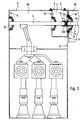
- Fig. 1 is a gas-insulated switchgear according to the invention in its entirety by the reference numeral 1.
- the switchgear 1 is used in particular for re-clamping multiphase medium voltages. It has three juxtaposed switchgear assemblies 2.
- Each of the switchgear assemblies 2 has a gas-tight gas container 3, in which switching elements and at least one busbar 4 are arranged. To isolate the switching elements and the busbars 4, the gas container 3 is filled with insulating gas.
- the busbars 4 of the switchgear assemblies 2 have a separate line 4a, 4b, 4c for each phase of the voltage to be switched in the switchgear 1 (cf. Fig. 2 ).
- the individual lines 4a, 4b, 4c are arranged one behind the other in the plane of the drawing.
- Adjacent switchgear assemblies 2a, 2b are mechanically interconnected.
- the lines 4a, 4b, 4c of the busbars 4 of the adjacent switchgear assemblies 2a, 2b are electrically connected to each other.
- the lines 4a, 4b, 4c of the busbar 4 of the first switchgear assembly 2a are led out of the gas container 3 on a first side 5 of the switchgear assembly 2a.
- the lines 4 a, 4 b, 4 c open into a gas-tight mounting space 7 which is separated gas-tight from the gas container 3.
- the mounting space 7 is arranged inside the gas container 3.
- the part of the gas container 3 outside the mounting space 7 is referred to as a switchgear room.
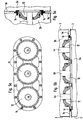
- the mounting space 7 has a side by side arranged switchgear assemblies 2a, 2b accessible from the outside mounting opening 8, which is closed gas-tight with a lid 9 (see. Fig. 3 and Fig. 4 ).
- the mounting space 7 has a connection opening 10 which faces the busbar 4 when the switchgear arrangements 2 a, 2 b are arranged side by side, leading out of the gas tank 3 of the adjacent switchgear arrangement 2 b 4 a, 4 b, 4 c.
- the mounting space 7 has a valve arrangement 11 for filling the mounting space 7 with insulating gas.
- the valve assembly 11 is in the Fig. 3 and 4 formed as a valve operable from the outside, which is opened from the outside after completion of the mechanical and electrical connection work, ie in gas-tightly closed mounting space 7, so that insulating gas from the switchgear room can flow into the mounting space 7.
- switching array 2a has, in contrast to the switchgear assemblies 2 of Fig. 1 and 2 an additional bulkhead between the power switch room and the space for the busbars 4 and the circuit breaker on.
- the ends of the opening into the recesses 12 lines 4a, 4b, 4c of the busbar 4 close flush with the surrounding the recesses 12 wall 3a of the gas container 3 from.
- the lines 4a, 4b, 4c can also be set back slightly relative to the wall 3a into the interior of the gas container 3.
- connection opening 10 is for each line 4a, 4b, 4c, a contact element 13 for establishing an electrically conductive connection between the lines 4a, 4b, 4c of the busbar 4 of the switchgear assembly 2a and the lines 4a, 4b, 4c of the busbar 4 of the adjacent switchgear assembly 2b arranged.
- the contact element 13 is made of an electrically conductive material. It is as a pipeline is formed, which is divided longitudinally into two pipe segments 13a, 13b. The pipe segments 13a, 13b are arranged on the lines 4a, 4b, 4c of the busbars 4 of the adjacent switchgear assemblies 2a, 2b axially displaceable and resiliently clamped.
- the contact element 13 can also be configured differently and, for example, consist of more than two pipe segments 13 a, 13 b. However, it must always be designed so that it bridges the distance between ends of the lines 4a, 4b, 4c of the busbars 4 of two adjacent switchgear assemblies 2a, 2b. The distance is chosen so that it is sufficiently large after removal of the contact element 13 that it meets the requirements of the withstand voltage of the switchgear assembly 2 in the filled with insulating gas state. The distance thus forms a separation line z. B. can be made when working on the switchgear and work on the disconnected part of the switchgear 1 is allowed in pending busbar voltage.
- the adjacent switchgear assemblies 2a, 2b are mechanically connected to one another in such a way that the mounting space 7 is in gas-tight connection with the recesses 12 via the connection opening 10.
- connecting elements 14 are used for the mechanical connection of the adjacent switchgear assemblies 2a, 2b connecting elements 14 are used.
- the connecting elements 14 are preferably formed as screws.
- a sealing member 15 is disposed around the connection hole 10 and around the recesses 12. The sealing element 15 is clamped between the walls 3a and 3b such that the mounting space 7 is sealed gas-tight by the wall 3a of the gas container 3 of the adjacent switching field arrangement 2b.
- the wall 3b on the side 6 of the gas container 3 of the switchgear assembly 2a, on which the mounting space 7 is formed, is designed to be partially yielding around the mechanical connection of the adjacent switchgear assemblies 2a, 2b.
- the resilient portion 16 of the wall 3b consists of a thin sheet with a wave-shaped profile.
- a switchgear 1 In order to construct a switchgear 1 according to the invention from the individual switchgear arrangements 2, the switchgear arrangements 2 are initially arranged next to one another. The covers 9 of the mounting spaces 7 of the panel assemblies 2 are opened. Between each two adjacent switchgear assemblies 2 a, 2 b, a mechanical connection is made in the mounting space 7 by means of the connecting elements 14. By means of the contact elements 13 is through the connection opening 10 of the mounting space 7 between the lines 4a, 4b, 4c of the busbars 4 of the adjacent switchgear assemblies 2a, 2b made an electrically conductive connection. After completion of the connection work, the mounting spaces 7 are sealed gas-tight with the covers 9.
- the connecting openings 10 of the mounting spaces 7 are sealed gas-tight by the walls 3a of the adjacent switchgear assemblies 2b. Then, the valve assemblies 11, which are arranged between the mounting chambers 7 and the gas containers 3, operated from the outside, so that the excess contained in the gas containers 3 of insulating gas can flow into the mounting chambers 7. Before filling the mounting space 7 with insulating this can also be evacuated.
- Fig. 5a to 5c are the three lines 4a, 4b, 4c of the busbar 4 shown as they emerge laterally on the wall 3a of the panel assemblies 2 from the gas containers 3.
- the lines 4a, 4b, 4c of the busbar 4 each open into a separate recess 12.
- the connecting elements 14 are arranged around the recesses 12 around.
Landscapes
- Engineering & Computer Science (AREA)
- Power Engineering (AREA)
- Gas-Insulated Switchgears (AREA)
Claims (12)
- Installation de commutation (1) isolée des gaz comprimés, en particulier pour des moyennes tensions multiphases, comportant au moins deux systèmes de tableau de commande (2a, 2b) juxtaposés, qui comportent chacun un réservoir de gaz (3) étanche aux gaz et rempli de gaz isolant, dans lequel sont disposés des éléments de commutation et au moins un rail collecteur (4), qui comporte une ligne (4a, 4b, 4c) pour chaque phase de la tension à commander dans l'installation de commutation (1), les lignes (4a, 4b, 4c) dans des systèmes de tableau de commande (2a, 2b) adjacents étant reliées entre elles de manière électroconductrice, les lignes (4a, 4b, 4c) du rail collecteur (4) débouchant sur un côté (6) du système de tableau de commande (2a) dans au moins un espace de montage (7) étanche aux gaz et séparé de manière étanche aux gaz du réservoir de gaz (3), lequel espace de montage comporte une ouverture de montage (8) qui, en présence de systèmes de tableau de commande (2a, 2b) juxtaposés, est accessible de l'extérieur et qui peut être fermée de manière étanche aux gaz par un couvercle (9), lequel espace de montage comporte une ouverture de liaison (10), qui peut être fermée de manière étanche aux gaz et qui, en présence de systèmes de tableau de commande (2a, 2b) juxtaposés, est orientée vers les lignes (4a, 4b, 4c) menées hors du réservoir de gaz (3) du système de tableau de commande (2b) adjacent, lequel espace de montage comporte un système de vanne (11) pour remplir l'espace de montage (7) avec le gaz isolant, caractérisée en ce que l'espace de montage (7) est située à l'intérieur du réservoir de gaz (3).
- Installation de commutation (1) selon la revendication 1, caractérisée en ce que les lignes (4a, 4b, 4c) du rail collecteur (4) sont guidées hors du réservoir de gaz (3) sur un autre côté (5), différent du côté (6) du système de tableau de commande (2a) sur lequel est disposé ledit au moins un espace de montage (7).
- Installation de commutation (1) selon la revendication 2, caractérisée en ce que la paroi (3a) du réservoir de gaz (3), sur le côté (5) du système de tableau de commande (2a), sur lequel les lignes (4a, 4b, 4c) du rail collecteur (4) sont guidées hors du réservoir de gaz (3), comporte au moins un creux (12), dans lequel débouchent les lignes (4a, 4b, 4c) du rail collecteur (4).
- Installation de commutation (1) selon la revendication 3, caractérisée en ce que les extrémités des lignes (4a, 4b, 4c) du rail collecteur (4), lesquelles débouchent dans ledit au moins un creux (12), sont situées à fleur de la paroi (3a) du réservoir de gaz (3), qui entoure le creux (12).
- Installation de commutation (1) selon la revendication 3 ou 4, caractérisée en ce que dans l'ouverture de liaison (10) est disposé au moins un élément de contact (13) destiné à établir la liaison électroconductrice entre les lignes (4a, 4b, 4c) du rail collecteur (4) du système de tableau de commande (2a) et les lignes (4a, 4b, 4c) du rail collecteur (4) du système de tableau de commande (2b) adjacent.
- Installation de commutation (1) selon la revendication 5, caractérisée en ce que l'élément de contact (13) est un élément tubulaire réalisé dans un matériau électroconducteur.
- système de tableau de commande (1) selon la revendication 6, caractérisée en ce que l'élément de contact (13) est réalisé sous forme de conduit tubulaire qui est divisé, dans le sens de la longueur, en deux segments tubulaires (13a, 13b), qui sont disposés de manière mobile axialement et en étant serrés de manière flexible sur les lignes (4a, 4b, 4c) du rail collecteur (4) des systèmes de tableau de commande (2a, 2b) adjacents.
- Installation de commutation (1) selon l'une quelconque des revendications 3 à 7, caractérisée en ce que les systèmes de tableau de commande (2a, 2b) adjacents sont reliés mécaniquement entre eux de telle sorte que l'espace de montage (7) est relié de manière étanche aux gaz avec le creux (12) via l'ouverture de liaison (10).
- Installation de commutation (1) selon la revendication 8, caractérisée en ce que les systèmes de tableau de commande (2a, 2b) adjacents sont reliés mécaniquement entre eux par des éléments d'assemblage (14), de telle sorte qu'un élément d'étanchéité (15), disposé entre les réservoirs de gaz (3) des systèmes de tableau de commande (2a, 2b) adjacents autour de ladite au moins une ouverture de liaison (10) et ledit au moins un creux (12), est bloquée de manière étanche aux gaz entre les réservoirs de gaz (3).
- Installation de commutation (1) selon l'une quelconque des revendications 1 à 9, caractérisée en ce que les lignes (4a, 4b, 4c) du rail collecteur (4) débouchent sur le côté (5) du système de tableau de commande (2a) dans un creux (12) commun et débouchent sur l'autre côté (6) du système de tableau de commande (2a) dans un espace de montage (7) commun.
- Installation de commutation (1) selon l'une quelconque des revendications 1 à 10, caractérisée en ce que le système de vanne (11), destiné à remplir l'espace de montage (7) avec le gaz isolant, est disposé entre l'espace de montage (7) et le réservoir de gaz (3) de manière apte à être commandé de l'extérieur.
- Installation de commutation (1) selon l'une quelconque des revendications 1 à 11, caractérisée en ce que, en présence de systèmes de tableau de commande (2) juxtaposés, le système de vanne (11), destiné à remplir l'espace de montage (7) avec le gaz isolant, est disposé de manière accessible de l'extérieur dans une paroi de l'espace de montage (7).
Applications Claiming Priority (2)
| Application Number | Priority Date | Filing Date | Title |
|---|---|---|---|
| DE19850693A DE19850693B4 (de) | 1998-11-04 | 1998-11-04 | Druckgasisolierte Schaltanlage |
| DE19850693 | 1998-11-04 |
Publications (2)
| Publication Number | Publication Date |
|---|---|
| EP0999623A1 EP0999623A1 (fr) | 2000-05-10 |
| EP0999623B1 true EP0999623B1 (fr) | 2009-02-18 |
Family
ID=7886572
Family Applications (1)
| Application Number | Title | Priority Date | Filing Date |
|---|---|---|---|
| EP99117086A Expired - Lifetime EP0999623B1 (fr) | 1998-11-04 | 1999-08-31 | Installation de commutation à gaz isolant |
Country Status (2)
| Country | Link |
|---|---|
| EP (1) | EP0999623B1 (fr) |
| DE (2) | DE19850693B4 (fr) |
Families Citing this family (3)
| Publication number | Priority date | Publication date | Assignee | Title |
|---|---|---|---|---|
| EP3323180B1 (fr) * | 2015-09-11 | 2020-12-16 | Siemens Aktiengesellschaft | Module électrique à isolation gazeuse |
| WO2020115849A1 (fr) * | 2018-12-06 | 2020-06-11 | 三菱電機株式会社 | Dispositif de connexion de ligne de bus, appareillage de commutation, et procédé de connexion de dispositif de connexion de ligne de bus |
| CN117578254B (zh) * | 2024-01-19 | 2024-03-29 | 四川电器集团中低压智能配电有限公司 | 一种智能箱式大电流环保气体绝缘开关设备 |
Family Cites Families (7)
| Publication number | Priority date | Publication date | Assignee | Title |
|---|---|---|---|---|
| DE4001909A1 (de) * | 1990-01-24 | 1991-07-25 | Sachsenwerk Ag | Einrichtung und verfahren zur verbindung von in getrennten gehaeusen untergebrachten gasisolierten schaltanlagen |
| DE4210773C2 (de) * | 1992-04-01 | 1995-11-02 | Felten & Guilleaume Energie | Metallgekapselte, druckgasisolierte SF¶6¶-Schaltanlage mit einer Sammelschienenanordnung |
| DE4404339A1 (de) * | 1994-02-11 | 1995-08-17 | Sachsenwerk Ag | Schaltanlage mit einem Verbindungskanal |
| DE4404340A1 (de) * | 1994-02-11 | 1995-08-17 | Sachsenwerk Ag | Schaltanlage mit einem Verbindungskanal |
| DE19613553A1 (de) * | 1996-04-04 | 1997-10-09 | Bayer Ag | Verfahren zur Herstellung mit integrierter Fraktionierung und Reinigung von aromatischen Polyamingemischen und deren Verwendung |
| DE19615553A1 (de) * | 1996-04-19 | 1997-10-23 | Abb Patent Gmbh | Sammelschienenkupplung durch die benachbarten Wände zweier nebeneinanderstehender Schaltfelder |
| DE19727855C1 (de) * | 1997-06-26 | 1998-11-12 | Siemens Ag | Gasisolierte Schaltanlage |
-
1998
- 1998-11-04 DE DE19850693A patent/DE19850693B4/de not_active Expired - Fee Related
-
1999
- 1999-08-31 EP EP99117086A patent/EP0999623B1/fr not_active Expired - Lifetime
- 1999-08-31 DE DE59914964T patent/DE59914964D1/de not_active Expired - Lifetime
Also Published As
| Publication number | Publication date |
|---|---|
| DE59914964D1 (de) | 2009-04-02 |
| EP0999623A1 (fr) | 2000-05-10 |
| DE19850693B4 (de) | 2007-01-25 |
| DE19850693A1 (de) | 2000-05-11 |
Similar Documents
| Publication | Publication Date | Title |
|---|---|---|
| EP0291762B1 (fr) | Installation de commutation polyphasée haute tension blindée à isolation gazeuse | |
| DE69513436T2 (de) | Schaltgerätmodul und Konfigurationen | |
| DE2754691C2 (de) | Ein- oder mehrphasig metallgekapselte, druckgasisolierte Hochspannungsschaltanlage | |
| EP0735637A2 (fr) | Dispositif de coupure ayant un caiter métallique mis à la terre et rempli d'un gaz isolant | |
| EP1719225A1 (fr) | Installation de commutation a isolation gazeuse dans une enveloppe | |
| DE4001192C2 (de) | Schaltstation im Baukastensystem | |
| DE19809839A1 (de) | Metallgekapselte, gasisolierte Schaltanlage mit gasgefüllten Behältern | |
| DE4320906C2 (de) | Gehäuse für einen druckgasisolierten Hochspannungs- Leistungs-Schalter | |
| EP0999623B1 (fr) | Installation de commutation à gaz isolant | |
| DE3331222C2 (fr) | ||
| EP0499606B1 (fr) | Appareillage de distribution haute tension tripolaire sous blindage metallique avec isolation par gaz comprime | |
| EP0796502B1 (fr) | Appareillage de commutation mis sous boitier metallique, comportant un interrupteur a vide | |
| EP0436256B1 (fr) | Installation de commutation avec un récipient blindé à isolation gazeuse et interrupteur rotatif multiposition | |
| DE10325683B3 (de) | Trennschalteranordnung | |
| EP0204082B1 (fr) | Enceinte moulée pour installation de commutation moyenne tension | |
| EP0667663B1 (fr) | Installation de commutation avec canal de connexion | |
| DE69004052T2 (de) | Modulares metallgekapseltes Mittelspannungsverteilungssystem. | |
| EP0999624B1 (fr) | Installation de commutation à gaz isolant | |
| DE19638746C1 (de) | Elektrische Anlage für den Mittelspannungsbereich | |
| EP0667662B1 (fr) | Installation de commutation avec canal de connexion | |
| DE19606213A1 (de) | Schaltfeld in einer elektrischen, metallgekapselten, gasisolierten Hochspannungsschaltanlage | |
| EP0813763B1 (fr) | Tableau pour sectionneurs de coupure en charge dans des installations blindees de commutation a tension moyenne | |
| DE29622654U1 (de) | Elektrische Anlage für den Mittelspannungsbereich | |
| EP0285545B1 (fr) | Disjoncteur électrique à haute tension particulièrement disjoncteur à gaz comprimé | |
| EP0718941B1 (fr) | Installation électrique blindée à haute tension |
Legal Events
| Date | Code | Title | Description |
|---|---|---|---|
| PUAI | Public reference made under article 153(3) epc to a published international application that has entered the european phase |
Free format text: ORIGINAL CODE: 0009012 |
|
| 17P | Request for examination filed |
Effective date: 19991211 |
|
| AK | Designated contracting states |
Kind code of ref document: A1 Designated state(s): DE ES FR GB IT |
|
| AX | Request for extension of the european patent |
Free format text: AL;LT;LV;MK;RO;SI |
|
| AKX | Designation fees paid |
Free format text: DE ES FR GB IT |
|
| RAP1 | Party data changed (applicant data changed or rights of an application transferred) |
Owner name: AREVA SACHSENWERK GMBH |
|
| GRAP | Despatch of communication of intention to grant a patent |
Free format text: ORIGINAL CODE: EPIDOSNIGR1 |
|
| GRAS | Grant fee paid |
Free format text: ORIGINAL CODE: EPIDOSNIGR3 |
|
| GRAA | (expected) grant |
Free format text: ORIGINAL CODE: 0009210 |
|
| AK | Designated contracting states |
Kind code of ref document: B1 Designated state(s): DE ES FR GB IT |
|
| REG | Reference to a national code |
Ref country code: GB Ref legal event code: FG4D Free format text: NOT ENGLISH |
|
| REF | Corresponds to: |
Ref document number: 59914964 Country of ref document: DE Date of ref document: 20090402 Kind code of ref document: P |
|
| PG25 | Lapsed in a contracting state [announced via postgrant information from national office to epo] |
Ref country code: ES Free format text: LAPSE BECAUSE OF FAILURE TO SUBMIT A TRANSLATION OF THE DESCRIPTION OR TO PAY THE FEE WITHIN THE PRESCRIBED TIME-LIMIT Effective date: 20090529 |
|
| PLBE | No opposition filed within time limit |
Free format text: ORIGINAL CODE: 0009261 |
|
| STAA | Information on the status of an ep patent application or granted ep patent |
Free format text: STATUS: NO OPPOSITION FILED WITHIN TIME LIMIT |
|
| 26N | No opposition filed |
Effective date: 20091119 |
|
| GBPC | Gb: european patent ceased through non-payment of renewal fee |
Effective date: 20090831 |
|
| REG | Reference to a national code |
Ref country code: FR Ref legal event code: ST Effective date: 20100430 |
|
| PG25 | Lapsed in a contracting state [announced via postgrant information from national office to epo] |
Ref country code: FR Free format text: LAPSE BECAUSE OF NON-PAYMENT OF DUE FEES Effective date: 20090831 |
|
| PG25 | Lapsed in a contracting state [announced via postgrant information from national office to epo] |
Ref country code: GB Free format text: LAPSE BECAUSE OF NON-PAYMENT OF DUE FEES Effective date: 20090831 |
|
| PG25 | Lapsed in a contracting state [announced via postgrant information from national office to epo] |
Ref country code: IT Free format text: LAPSE BECAUSE OF FAILURE TO SUBMIT A TRANSLATION OF THE DESCRIPTION OR TO PAY THE FEE WITHIN THE PRESCRIBED TIME-LIMIT Effective date: 20090218 |
|
| REG | Reference to a national code |
Ref country code: DE Ref legal event code: R084 Ref document number: 59914964 Country of ref document: DE |
|
| REG | Reference to a national code |
Ref country code: DE Ref legal event code: R084 Ref document number: 59914964 Country of ref document: DE Effective date: 20110728 |
|
| PGFP | Annual fee paid to national office [announced via postgrant information from national office to epo] |
Ref country code: DE Payment date: 20140729 Year of fee payment: 16 |
|
| REG | Reference to a national code |
Ref country code: DE Ref legal event code: R119 Ref document number: 59914964 Country of ref document: DE |
|
| PG25 | Lapsed in a contracting state [announced via postgrant information from national office to epo] |
Ref country code: DE Free format text: LAPSE BECAUSE OF NON-PAYMENT OF DUE FEES Effective date: 20160301 |