EP0999948B1 - Verfahren zur steuerung einer brennkraftmaschine - Google Patents
Verfahren zur steuerung einer brennkraftmaschine Download PDFInfo
- Publication number
- EP0999948B1 EP0999948B1 EP98941488A EP98941488A EP0999948B1 EP 0999948 B1 EP0999948 B1 EP 0999948B1 EP 98941488 A EP98941488 A EP 98941488A EP 98941488 A EP98941488 A EP 98941488A EP 0999948 B1 EP0999948 B1 EP 0999948B1
- Authority
- EP
- European Patent Office
- Prior art keywords
- speed
- internal combustion
- vehicle
- engine
- combustion engine
- Prior art date
- Legal status (The legal status is an assumption and is not a legal conclusion. Google has not performed a legal analysis and makes no representation as to the accuracy of the status listed.)
- Expired - Lifetime
Links
- 238000000034 method Methods 0.000 title claims description 16
- 238000002485 combustion reaction Methods 0.000 title claims description 15
- 239000000446 fuel Substances 0.000 claims description 20
- 230000008569 process Effects 0.000 description 6
- 230000009471 action Effects 0.000 description 4
- 230000007246 mechanism Effects 0.000 description 3
- 230000000881 depressing effect Effects 0.000 description 2
- 230000001133 acceleration Effects 0.000 description 1
- 230000005540 biological transmission Effects 0.000 description 1
- 230000006835 compression Effects 0.000 description 1
- 238000007906 compression Methods 0.000 description 1
- 238000006073 displacement reaction Methods 0.000 description 1
- 230000005021 gait Effects 0.000 description 1
- 238000010438 heat treatment Methods 0.000 description 1
Images

Classifications
-
- F—MECHANICAL ENGINEERING; LIGHTING; HEATING; WEAPONS; BLASTING
- F02—COMBUSTION ENGINES; HOT-GAS OR COMBUSTION-PRODUCT ENGINE PLANTS
- F02D—CONTROLLING COMBUSTION ENGINES
- F02D31/00—Use of speed-sensing governors to control combustion engines, not otherwise provided for
- F02D31/001—Electric control of rotation speed
- F02D31/007—Electric control of rotation speed controlling fuel supply
-
- B—PERFORMING OPERATIONS; TRANSPORTING
- B60—VEHICLES IN GENERAL
- B60W—CONJOINT CONTROL OF VEHICLE SUB-UNITS OF DIFFERENT TYPE OR DIFFERENT FUNCTION; CONTROL SYSTEMS SPECIALLY ADAPTED FOR HYBRID VEHICLES; ROAD VEHICLE DRIVE CONTROL SYSTEMS FOR PURPOSES NOT RELATED TO THE CONTROL OF A PARTICULAR SUB-UNIT
- B60W10/00—Conjoint control of vehicle sub-units of different type or different function
- B60W10/04—Conjoint control of vehicle sub-units of different type or different function including control of propulsion units
-
- B—PERFORMING OPERATIONS; TRANSPORTING
- B60—VEHICLES IN GENERAL
- B60W—CONJOINT CONTROL OF VEHICLE SUB-UNITS OF DIFFERENT TYPE OR DIFFERENT FUNCTION; CONTROL SYSTEMS SPECIALLY ADAPTED FOR HYBRID VEHICLES; ROAD VEHICLE DRIVE CONTROL SYSTEMS FOR PURPOSES NOT RELATED TO THE CONTROL OF A PARTICULAR SUB-UNIT
- B60W10/00—Conjoint control of vehicle sub-units of different type or different function
- B60W10/18—Conjoint control of vehicle sub-units of different type or different function including control of braking systems
-
- B—PERFORMING OPERATIONS; TRANSPORTING
- B60—VEHICLES IN GENERAL
- B60W—CONJOINT CONTROL OF VEHICLE SUB-UNITS OF DIFFERENT TYPE OR DIFFERENT FUNCTION; CONTROL SYSTEMS SPECIALLY ADAPTED FOR HYBRID VEHICLES; ROAD VEHICLE DRIVE CONTROL SYSTEMS FOR PURPOSES NOT RELATED TO THE CONTROL OF A PARTICULAR SUB-UNIT
- B60W30/00—Purposes of road vehicle drive control systems not related to the control of a particular sub-unit, e.g. of systems using conjoint control of vehicle sub-units
- B60W30/18—Propelling the vehicle
- B60W30/1819—Propulsion control with control means using analogue circuits, relays or mechanical links
-
- F—MECHANICAL ENGINEERING; LIGHTING; HEATING; WEAPONS; BLASTING
- F02—COMBUSTION ENGINES; HOT-GAS OR COMBUSTION-PRODUCT ENGINE PLANTS
- F02D—CONTROLLING COMBUSTION ENGINES
- F02D11/00—Arrangements for, or adaptations to, non-automatic engine control initiation means, e.g. operator initiated
- F02D11/06—Arrangements for, or adaptations to, non-automatic engine control initiation means, e.g. operator initiated characterised by non-mechanical control linkages, e.g. fluid control linkages or by control linkages with power drive or assistance
- F02D11/10—Arrangements for, or adaptations to, non-automatic engine control initiation means, e.g. operator initiated characterised by non-mechanical control linkages, e.g. fluid control linkages or by control linkages with power drive or assistance of the electric type
Definitions
- the present invention relates to a method for controlling an internal combustion engine.
- the the present invention relates more particularly control of an internal combustion engine fitted to an agricultural tractor.
- a method according to the preamble of claim 1 is known from document DE-A-4 206 291.
- the position of these two accelerators separate is transmitted to a device power control electronics by the motor which then controls the latter in function of the larger of the two pieces of information.
- the electronic control unit then acts directly on the quantity of fuel injected at through the injector control or the fuel pump.
- This arrangement has the disadvantage not to take into account the driver's action on the braking control (s) of the vehicle so that the power supplied by the engine is reduced, canceled or made negative (engine brake) as soon as the driver brakes independently the position of the accelerators.
- the object of the present invention is therefore to overcome these drawbacks by proposing a engine control process which takes into account the driver's action on the brakes and the position of the accelerators.
- limiting the supply of fuel is operated as long as the brake pedal is requested and as long as the vehicle speed remains above the given threshold speed.
- the throttle lever is disconnected from the engine control and the engine is then only controlled by the accelerator pedal and this, as long as the driver has not brought the throttle lever in rest position.
- the present invention relates more particularly motor vehicles comprising two separate accelerators controlling the load engine such as for example tractors farm.
- the agricultural tractor referenced 1 to the Figure 1 conventionally comprises a motor with internal combustion 2 of the ignition type compression.
- This motor 2 has a housing control electronics 3 which controls according to strategies adapted to the fuel supply of the engine especially from the position of two separate accelerators.
- This case 3 acts directly on the opening of the injectors fuel in the case of a "common" type circuit rail "or even on the flow of the pump to fuel in the case of a control pump electronic.
- the two accelerators acting on the engine load control 2 are made up by the pedal 5 operated at the foot by the driver while the second accelerator is constituted by the lever 4 operated by hand by the driver.
- Pedal 5 is brought back automatically to the rest position by a adapted return mechanism while the lever 4, it is devoid of any recall mechanism.
- the displacement of each of the two accelerators 4 and 5, and the positions reached are transmitted to the electronic control unit 3 which controls then the fuel supply depending on the greater of these two values.
- the supply of fuel is also determined by the box electronic depending on. the depression of the brake pedal 6.
- the brake pedal 6 in question acts on the so-called "service” brakes by opposition to emergency or parking brakes which are ordered by other means.
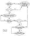
- the first step is to recognize the brake pedal position. If the pedal is at rest, the strategy used is the strategy classic of controlling the engine from from the largest of the positions reached by the pedal 5 and throttle 4.
- Speed information of the vehicle is determined either by a device appropriate either by multiplying the engine speed by the transmission ratio.
- the supply of fuel is reduced or even stopped until bringing back engine speed at idle speed so that reduce engine power and therefore improve the braking regardless of the positions of the two accelerators and in particular whatever the position of the joystick 4.
- This action on food in fuel is operated as long as the brake pedal is requested, even if the vehicle speed becomes lower than the speed Vref1 and therefore possibly until the vehicle comes to a complete stop.
- Vref2 a threshold speed
- lever 4 If the position of lever 4 is not at rest, then the engine is controlled, not at from the largest of the positions reached by pedal 5 and throttle lever 4, but only by the position given by the accelerator pedal 5 and this until the lever 4 is returned to its rest position this which then allows to find a functioning classic where the engine is then controlled from from the largest of the positions reached by the pedal 5 and throttle 4.
- This strategy is to prevent the vehicle after having slowed down considerably, does not re-accelerate brutally to reach the speed of setpoint given by the position of the lever 4 in case the latter has not been brought back at rest during braking.
- This controller 4 is therefore disconnected from the engine control as long as the driver did not return it to the position of rest and it is only once the lever 4 brought back in its rest position that it becomes again active on motor control.
- Vref2 is therefore used to evaluate the amount of braking experienced by the vehicle.
- the vehicle speed after braking is greater than Vref2
- Vref2 the vehicle speed after braking is less than Vref2
Landscapes
- Engineering & Computer Science (AREA)
- Chemical & Material Sciences (AREA)
- Combustion & Propulsion (AREA)
- Mechanical Engineering (AREA)
- Transportation (AREA)
- General Engineering & Computer Science (AREA)
- Automation & Control Theory (AREA)
- Electrical Control Of Air Or Fuel Supplied To Internal-Combustion Engine (AREA)
- Control Of Throttle Valves Provided In The Intake System Or In The Exhaust System (AREA)
- Control Of Vehicle Engines Or Engines For Specific Uses (AREA)
Claims (6)
- Verfahren zur Steuerung eines Verbrennungsmotors (2), der ein Fahrzeug (1) ausrüstet und mit einem Handgashebel (4) und einem Gaspedal (5) zusammenwirkt, durch welches die Menge an einzuspritzendem Kraftstoff bestimmt wird, wobei die Kraftstoffmenge bestimmt wird durch die jeweiligen Positionen des Gaspedals (4) und des Handgashebels (5) korrigiert wird abhängig von der Position von mindestens einem Bremselement (6) des Fahrzeugs (1), dadurch gekennzeichnet, dass das Drücken des Bremselements (6) nur berücksichtigt wird, wenn die Geschwindigkeit des Fahrzeugs eine gegebene Grenzgeschwindigkeit (Vref1) überschreitet.
- Verfahren zur Steuerung eines Verbrennungsmotors gemäß Anspruch 1, dadurch gekennzeichnet, dass welche die jeweiligen Positionen des Gaspedals (5) und des Handgashebels (4) auch seien, das Drücken des Bremselements (6) eine Begrenzung der Kraftstoffversorgung bewirkt, bis die Drehzahl des Motors die Drehzahl des Lehrlaufs erreicht
- Verfahren zur Steuerung eines Verbrennungsmotors gemäß Anspruch 2, dadurch gekennzeichnet, dass die Begrenzung der Kraftstoffversorgung anhält, solange das Bremselement (6) gedrückt wird.
- Verfahren zur Steuerung eines Verbrennungsmotors gemäß Anspruch 1, dadurch gekennzeichnet, dass die Begrenzung der Kraftstoffversorgung ausgeführt wird, solange das Bremselement (6) gedrückt wird und solange die Geschwindigkeit des Fahrzeugs größer als die gegebene Grenzgeschwindigkeit (Vref1) bleibt.
- Verfahren zur Steuerung eines Verbrennungsmotors gemäß Anspruch 1, dadurch gekennzeichnet, dass die Begrenzung der Kraftstoffversorgung beibehalten wird, solange das Bremselement (6) gedrückt wird, sogar wenn die Geschwindigkeit des Fahrzeugs kleiner als die Grenzgeschwindigkeit (Vref1) wird.
- Verfahren zur Steuerung eines Verbrennungsmotors gemäß einem der Ansprüche 1 bis 5, dadurch gekennzeichnet, dass beim Loslassen des Bremselements (6), und wenn die Geschwindigkeit des Fahrzeugs eine zweite gegebene Grenzgeschwindigkeit (Vref2) übersteigt, der Handgashebel (4) von der Steuerung des Motors (2) abgekoppelt wird und der Motor (2) nur durch das Gaspedal (5) gesteuert wird, solange der Fahrer den Handgashebel (4) nicht in die Ruheposition zurückgeführt hat.
Applications Claiming Priority (3)
| Application Number | Priority Date | Filing Date | Title |
|---|---|---|---|
| FR9709855 | 1997-08-01 | ||
| FR9709855A FR2766874B1 (fr) | 1997-08-01 | 1997-08-01 | Procede de commande d'un moteur a combustion interne |
| PCT/FR1998/001687 WO1999006238A1 (fr) | 1997-08-01 | 1998-07-29 | Procede de commande d'un moteur a combustion interne |
Publications (2)
| Publication Number | Publication Date |
|---|---|
| EP0999948A1 EP0999948A1 (de) | 2000-05-17 |
| EP0999948B1 true EP0999948B1 (de) | 2004-02-25 |
Family
ID=9509915
Family Applications (1)
| Application Number | Title | Priority Date | Filing Date |
|---|---|---|---|
| EP98941488A Expired - Lifetime EP0999948B1 (de) | 1997-08-01 | 1998-07-29 | Verfahren zur steuerung einer brennkraftmaschine |
Country Status (6)
| Country | Link |
|---|---|
| US (1) | US6338697B1 (de) |
| EP (1) | EP0999948B1 (de) |
| DE (1) | DE69821944T2 (de) |
| ES (1) | ES2212333T3 (de) |
| FR (1) | FR2766874B1 (de) |
| WO (1) | WO1999006238A1 (de) |
Families Citing this family (8)
| Publication number | Priority date | Publication date | Assignee | Title |
|---|---|---|---|---|
| EP1529367A4 (de) | 2002-08-06 | 2011-08-03 | Privaris Inc | Verfahren zur sicheren aufnahme und sicherungsspeicherung von personengebondenen identitätsbereitigungen in elektronischen vorrichtungen |
| JP4039257B2 (ja) * | 2003-01-29 | 2008-01-30 | いすゞ自動車株式会社 | 燃料噴射量制御装置 |
| FR2892835B1 (fr) * | 2005-10-28 | 2008-01-18 | Airbus France Sas | Dispositif de commande de regime-moteur, procede de commande de regime-moteur et aeronef comportant un tel dispositif |
| US7702450B2 (en) | 2008-03-11 | 2010-04-20 | Deere & Company | Automatic idle adjustment and shutdown of vehicle |
| US8554419B2 (en) | 2010-05-28 | 2013-10-08 | Ford Global Technologies, Llc | Control of a vehicle powertrain in response to brake pedal input |
| JP5668848B2 (ja) * | 2011-06-16 | 2015-02-12 | トヨタ自動車株式会社 | 車両の制御装置 |
| JP5871572B2 (ja) * | 2011-11-14 | 2016-03-01 | 富士重工業株式会社 | 車両用出力制御装置 |
| DE102013112184B4 (de) * | 2013-11-06 | 2025-03-27 | Horsch Leeb Application Systems Gmbh | Verfahren und Vorrichtung zur Steuerung einer Fahrgeschwindigkeit einer landwirtschaftlichen Maschine |
Family Cites Families (14)
| Publication number | Priority date | Publication date | Assignee | Title |
|---|---|---|---|---|
| CA647489A (en) * | 1962-08-28 | Lynn H. Ewing | Accelerator control mechanism | |
| CA605066A (en) * | 1960-09-13 | General Motors Corporation | Automatic throttle control | |
| US1936149A (en) * | 1930-06-12 | 1933-11-21 | Bendix Brake Co | Vehicle control mechanism |
| US3354743A (en) * | 1959-12-03 | 1967-11-28 | Raymond C Strauss | Vehicle driving controls |
| US3338357A (en) * | 1964-05-04 | 1967-08-29 | Jesse R Hollins | Brake-operated accelerator release |
| US3331478A (en) * | 1965-05-21 | 1967-07-18 | Trifiletti Joseph | Electrical brake-controlled throttle cut-out system |
| US3495692A (en) * | 1967-10-25 | 1970-02-17 | Fremont Holgate | Safety accelerator brake control |
| JPS4945675B1 (de) * | 1969-07-07 | 1974-12-05 | ||
| US4244335A (en) * | 1978-11-17 | 1981-01-13 | Derussy John H | Control of vehicle engine fuel feed by electro-stress means |
| DE2952227A1 (de) * | 1979-12-22 | 1981-06-25 | Maschf Augsburg Nuernberg Ag | Einrichtung zur verhinderung des gasgebens bei gleichzeitiger betaetigung der motorauspuffbremse an nutzfahrzeugen, insbesondere lastkraftwagen |
| US4946012A (en) * | 1989-07-20 | 1990-08-07 | James G. Wells | Brake activated acceleration override apparatus |
| DE9106523U1 (de) * | 1991-05-27 | 1991-08-14 | meflex Telecontrol GmbH & Co, 6332 Ehringshausen | Handgas-Betätigung für Fahrzeuge mit Hub- und/oder Arbeitseinrichtungen |
| US5439429A (en) * | 1993-11-23 | 1995-08-08 | Lee; Steven P. | Vehicle safety system for correcting simultaneous actuation of brake and acceleration pedals |
| US5480364A (en) * | 1994-08-15 | 1996-01-02 | Caterpillar Inc. | Elevated idle speed control and method of operating same |
-
1997
- 1997-08-01 FR FR9709855A patent/FR2766874B1/fr not_active Expired - Fee Related
-
1998
- 1998-07-29 DE DE69821944T patent/DE69821944T2/de not_active Expired - Lifetime
- 1998-07-29 EP EP98941488A patent/EP0999948B1/de not_active Expired - Lifetime
- 1998-07-29 ES ES98941488T patent/ES2212333T3/es not_active Expired - Lifetime
- 1998-07-29 WO PCT/FR1998/001687 patent/WO1999006238A1/fr not_active Ceased
- 1998-07-29 US US09/463,408 patent/US6338697B1/en not_active Expired - Fee Related
Also Published As
| Publication number | Publication date |
|---|---|
| ES2212333T3 (es) | 2004-07-16 |
| DE69821944T2 (de) | 2004-12-09 |
| WO1999006238A1 (fr) | 1999-02-11 |
| EP0999948A1 (de) | 2000-05-17 |
| US6338697B1 (en) | 2002-01-15 |
| DE69821944D1 (de) | 2004-04-01 |
| FR2766874B1 (fr) | 1999-10-15 |
| FR2766874A1 (fr) | 1999-02-05 |
Similar Documents
| Publication | Publication Date | Title |
|---|---|---|
| EP2139740B1 (de) | Unterstützungssystem zum befahren von steigungen für automobile | |
| FR2528515A1 (fr) | Procede d'entrainement de vehicules automobiles comportant un volant d'inertie avec differentiel et un systeme d'entrainement mettant en oeuvre le procede | |
| US5505671A (en) | Method for controlling the operating sequences of a motor vehicle equipped with an automatic transmission | |
| EP0999948A1 (de) | Verfahren zur steuerung einer brennkraftmaschine | |
| FR2927040A1 (fr) | Procede de fonctionnement d'un systeme d'assistance au demarrage d'un vehicule automobile en cote | |
| EP3292032B1 (de) | Verfahren zur verwaltung präventiver genehmigungsgradienten während der entschleunigung | |
| EP2929168B1 (de) | Verfahren zum selektiven abschalten einer einspritzung in einen oder mehrere zylinder eines verbrennungsmotors und entsprechendes kraftfahrzeug | |
| WO2011086252A1 (fr) | Procede et dispositif pour obtenir un decollage a forte charge de vehicules hybrides | |
| FR3023589A1 (fr) | Procede pour controler une envolee de regime d'un moteur a combustion interne d'un vehicule en deplacement, lors d'un changement de rapport de boite de vitesses | |
| FR2630501A1 (fr) | Procede et dispositif pour commander l'alimentation en carburant pour un moteur a combustion interne entrainant un vehicule | |
| WO1994024429A1 (fr) | Procede de commande d'un moteur a combustion interne lors d'une entree en regime de ralenti | |
| FR2870484A1 (fr) | Procede et dispositif de gestion d'un vehicule | |
| EP3207238B1 (de) | Verfahren zur unterbrechung der kraftstoffeinspritzung in eine brennkraftmaschine | |
| EP2941560A1 (de) | Verfahren zur steuerung des motormomentes während der entschleunigung mit injektionsstopp und entsprechendes fahrzeug | |
| EP1995449A2 (de) | Verfahren zur Steuerung des Ausschaltens und automatischen Neustarts eines Fahrzeugmotors in Abhängigkeit vom Gefälle | |
| FR2780350A1 (fr) | Vehicule automobile comportant un dispositif de regulation automatique de la vitesse | |
| EP2512897A1 (de) | Verfahren und vorrichtung zur kompensation des durchzugskraftverlustes bei einem fahrzeug | |
| EP1590561B1 (de) | Verfahren und vorrichtung zur steuerung der antriebseinheit eines durch einen verbrennungsmotor angetriebenen fahrzeuges | |
| FR2935306A1 (fr) | Chaine de transmission d'un moteur a combustion interne comprenant un volant a inertie variable, son unite de commande ainsi qu'un procede de commande d'arret et de demarrage automatiques du moteur. | |
| WO2026052905A1 (fr) | Procede de gestion du freinage d'un vehicule automobile | |
| FR3144087A1 (fr) | Procédé de commande d’un ensemble électrique d’un véhicule automobile à moteur à combustion interne à boite de vitesses manuelle hybridé | |
| FR3132687A1 (fr) | Procede de determination de la disponibilite d’une fonction d’arret et de redemarrage d’un moteur thermique de vehicule | |
| EP3077262B1 (de) | Verfahren zur steuerung der übertragung von drehmomenten bei einem fahrzeug je nach steigung | |
| FR3146430A1 (fr) | Procédé de gestion d’un moteur d’un véhicule pour éviter une suraccélération | |
| WO2024105320A1 (fr) | Procede de prediction d'un demarrage moteur par detection d'une commande de retrogradage |
Legal Events
| Date | Code | Title | Description |
|---|---|---|---|
| PUAI | Public reference made under article 153(3) epc to a published international application that has entered the european phase |
Free format text: ORIGINAL CODE: 0009012 |
|
| 17P | Request for examination filed |
Effective date: 20000107 |
|
| AK | Designated contracting states |
Kind code of ref document: A1 Designated state(s): BE DE ES GB IT NL SE |
|
| 17Q | First examination report despatched |
Effective date: 20020603 |
|
| GRAP | Despatch of communication of intention to grant a patent |
Free format text: ORIGINAL CODE: EPIDOSNIGR1 |
|
| GRAS | Grant fee paid |
Free format text: ORIGINAL CODE: EPIDOSNIGR3 |
|
| GRAA | (expected) grant |
Free format text: ORIGINAL CODE: 0009210 |
|
| AK | Designated contracting states |
Kind code of ref document: B1 Designated state(s): BE DE ES GB IT NL SE |
|
| PG25 | Lapsed in a contracting state [announced via postgrant information from national office to epo] |
Ref country code: NL Free format text: LAPSE BECAUSE OF FAILURE TO SUBMIT A TRANSLATION OF THE DESCRIPTION OR TO PAY THE FEE WITHIN THE PRESCRIBED TIME-LIMIT Effective date: 20040225 |
|
| REG | Reference to a national code |
Ref country code: GB Ref legal event code: FG4D Free format text: NOT ENGLISH |
|
| REF | Corresponds to: |
Ref document number: 69821944 Country of ref document: DE Date of ref document: 20040401 Kind code of ref document: P |
|
| GBT | Gb: translation of ep patent filed (gb section 77(6)(a)/1977) | ||
| PG25 | Lapsed in a contracting state [announced via postgrant information from national office to epo] |
Ref country code: SE Free format text: LAPSE BECAUSE OF FAILURE TO SUBMIT A TRANSLATION OF THE DESCRIPTION OR TO PAY THE FEE WITHIN THE PRESCRIBED TIME-LIMIT Effective date: 20040525 |
|
| REG | Reference to a national code |
Ref country code: ES Ref legal event code: FG2A Ref document number: 2212333 Country of ref document: ES Kind code of ref document: T3 |
|
| NLV1 | Nl: lapsed or annulled due to failure to fulfill the requirements of art. 29p and 29m of the patents act | ||
| PLBE | No opposition filed within time limit |
Free format text: ORIGINAL CODE: 0009261 |
|
| STAA | Information on the status of an ep patent application or granted ep patent |
Free format text: STATUS: NO OPPOSITION FILED WITHIN TIME LIMIT |
|
| 26N | No opposition filed |
Effective date: 20041126 |
|
| REG | Reference to a national code |
Ref country code: DE Ref legal event code: R084 Ref document number: 69821944 Country of ref document: DE Effective date: 20120525 |
|
| PGFP | Annual fee paid to national office [announced via postgrant information from national office to epo] |
Ref country code: DE Payment date: 20130530 Year of fee payment: 16 Ref country code: ES Payment date: 20130729 Year of fee payment: 16 Ref country code: BE Payment date: 20130719 Year of fee payment: 16 |
|
| PGFP | Annual fee paid to national office [announced via postgrant information from national office to epo] |
Ref country code: GB Payment date: 20130719 Year of fee payment: 16 |
|
| PGFP | Annual fee paid to national office [announced via postgrant information from national office to epo] |
Ref country code: IT Payment date: 20130729 Year of fee payment: 16 |
|
| REG | Reference to a national code |
Ref country code: DE Ref legal event code: R119 Ref document number: 69821944 Country of ref document: DE |
|
| GBPC | Gb: european patent ceased through non-payment of renewal fee |
Effective date: 20140729 |
|
| REG | Reference to a national code |
Ref country code: DE Ref legal event code: R079 Ref document number: 69821944 Country of ref document: DE Free format text: PREVIOUS MAIN CLASS: B60K0041200000 Ipc: F02D0041000000 |
|
| PG25 | Lapsed in a contracting state [announced via postgrant information from national office to epo] |
Ref country code: IT Free format text: LAPSE BECAUSE OF NON-PAYMENT OF DUE FEES Effective date: 20140729 Ref country code: DE Free format text: LAPSE BECAUSE OF NON-PAYMENT OF DUE FEES Effective date: 20150203 |
|
| PG25 | Lapsed in a contracting state [announced via postgrant information from national office to epo] |
Ref country code: GB Free format text: LAPSE BECAUSE OF NON-PAYMENT OF DUE FEES Effective date: 20140729 |
|
| REG | Reference to a national code |
Ref country code: DE Ref legal event code: R119 Ref document number: 69821944 Country of ref document: DE Effective date: 20150203 Ref country code: DE Ref legal event code: R079 Ref document number: 69821944 Country of ref document: DE Free format text: PREVIOUS MAIN CLASS: B60K0041200000 Ipc: F02D0041000000 Effective date: 20150429 |
|
| REG | Reference to a national code |
Ref country code: ES Ref legal event code: FD2A Effective date: 20150826 |
|
| PG25 | Lapsed in a contracting state [announced via postgrant information from national office to epo] |
Ref country code: ES Free format text: LAPSE BECAUSE OF NON-PAYMENT OF DUE FEES Effective date: 20140730 |
|
| PG25 | Lapsed in a contracting state [announced via postgrant information from national office to epo] |
Ref country code: BE Free format text: LAPSE BECAUSE OF NON-PAYMENT OF DUE FEES Effective date: 20140731 |