EP1000312B1 - Munition de contre mesure - Google Patents
Munition de contre mesure Download PDFInfo
- Publication number
- EP1000312B1 EP1000312B1 EP99922246A EP99922246A EP1000312B1 EP 1000312 B1 EP1000312 B1 EP 1000312B1 EP 99922246 A EP99922246 A EP 99922246A EP 99922246 A EP99922246 A EP 99922246A EP 1000312 B1 EP1000312 B1 EP 1000312B1
- Authority
- EP
- European Patent Office
- Prior art keywords
- hollow
- charges
- munition according
- charge
- hollow charges
- Prior art date
- Legal status (The legal status is an assumption and is not a legal conclusion. Google has not performed a legal analysis and makes no representation as to the accuracy of the status listed.)
- Expired - Lifetime
Links
- 239000002360 explosive Substances 0.000 claims description 28
- 231100000518 lethal Toxicity 0.000 claims description 14
- 230000001665 lethal effect Effects 0.000 claims description 14
- 238000010304 firing Methods 0.000 claims description 8
- 239000011248 coating agent Substances 0.000 claims description 5
- 238000000576 coating method Methods 0.000 claims description 5
- 230000001360 synchronised effect Effects 0.000 claims description 3
- 239000011344 liquid material Substances 0.000 claims 1
- 239000002184 metal Substances 0.000 claims 1
- 238000005474 detonation Methods 0.000 description 9
- 230000006378 damage Effects 0.000 description 7
- 230000000694 effects Effects 0.000 description 5
- XLYOFNOQVPJJNP-UHFFFAOYSA-N water Substances O XLYOFNOQVPJJNP-UHFFFAOYSA-N 0.000 description 5
- 230000016571 aggressive behavior Effects 0.000 description 3
- 230000035939 shock Effects 0.000 description 3
- 229910000831 Steel Inorganic materials 0.000 description 2
- 238000004880 explosion Methods 0.000 description 2
- 239000010959 steel Substances 0.000 description 2
- 241000251169 Alopias vulpinus Species 0.000 description 1
- 239000004429 Calibre Substances 0.000 description 1
- RYGMFSIKBFXOCR-UHFFFAOYSA-N Copper Chemical compound [Cu] RYGMFSIKBFXOCR-UHFFFAOYSA-N 0.000 description 1
- 241000251729 Elasmobranchii Species 0.000 description 1
- 108010014172 Factor V Proteins 0.000 description 1
- 239000004809 Teflon Substances 0.000 description 1
- 229920006362 Teflon® Polymers 0.000 description 1
- XAGFODPZIPBFFR-UHFFFAOYSA-N aluminium Chemical compound [Al] XAGFODPZIPBFFR-UHFFFAOYSA-N 0.000 description 1
- 229910052782 aluminium Inorganic materials 0.000 description 1
- 230000003416 augmentation Effects 0.000 description 1
- 239000011230 binding agent Substances 0.000 description 1
- 229910052802 copper Inorganic materials 0.000 description 1
- 239000010949 copper Substances 0.000 description 1
- 230000001186 cumulative effect Effects 0.000 description 1
- 238000001514 detection method Methods 0.000 description 1
- 239000003999 initiator Substances 0.000 description 1
- 230000003993 interaction Effects 0.000 description 1
- 239000012263 liquid product Substances 0.000 description 1
- 239000000463 material Substances 0.000 description 1
- 238000005259 measurement Methods 0.000 description 1
- 238000006386 neutralization reaction Methods 0.000 description 1
- 238000005457 optimization Methods 0.000 description 1
- 230000008520 organization Effects 0.000 description 1
- 230000035515 penetration Effects 0.000 description 1
- 239000000047 product Substances 0.000 description 1
- 230000000135 prohibitive effect Effects 0.000 description 1
- 229920001187 thermosetting polymer Polymers 0.000 description 1
Images


Classifications
-
- B—PERFORMING OPERATIONS; TRANSPORTING
- B63—SHIPS OR OTHER WATERBORNE VESSELS; RELATED EQUIPMENT
- B63G—OFFENSIVE OR DEFENSIVE ARRANGEMENTS ON VESSELS; MINE-LAYING; MINE-SWEEPING; SUBMARINES; AIRCRAFT CARRIERS
- B63G7/00—Mine-sweeping; Vessels characterised thereby
- B63G7/02—Mine-sweeping means, Means for destroying mines
-
- F—MECHANICAL ENGINEERING; LIGHTING; HEATING; WEAPONS; BLASTING
- F42—AMMUNITION; BLASTING
- F42B—EXPLOSIVE CHARGES, e.g. FOR BLASTING, FIREWORKS, AMMUNITION
- F42B12/00—Projectiles, missiles or mines characterised by the warhead, the intended effect, or the material
- F42B12/02—Projectiles, missiles or mines characterised by the warhead, the intended effect, or the material characterised by the warhead or the intended effect
- F42B12/04—Projectiles, missiles or mines characterised by the warhead, the intended effect, or the material characterised by the warhead or the intended effect of armour-piercing type
- F42B12/10—Projectiles, missiles or mines characterised by the warhead, the intended effect, or the material characterised by the warhead or the intended effect of armour-piercing type with shaped or hollow charge
-
- F—MECHANICAL ENGINEERING; LIGHTING; HEATING; WEAPONS; BLASTING
- F42—AMMUNITION; BLASTING
- F42B—EXPLOSIVE CHARGES, e.g. FOR BLASTING, FIREWORKS, AMMUNITION
- F42B12/00—Projectiles, missiles or mines characterised by the warhead, the intended effect, or the material
- F42B12/02—Projectiles, missiles or mines characterised by the warhead, the intended effect, or the material characterised by the warhead or the intended effect
- F42B12/04—Projectiles, missiles or mines characterised by the warhead, the intended effect, or the material characterised by the warhead or the intended effect of armour-piercing type
- F42B12/10—Projectiles, missiles or mines characterised by the warhead, the intended effect, or the material characterised by the warhead or the intended effect of armour-piercing type with shaped or hollow charge
- F42B12/16—Projectiles, missiles or mines characterised by the warhead, the intended effect, or the material characterised by the warhead or the intended effect of armour-piercing type with shaped or hollow charge in combination with an additional projectile or charge, acting successively on the target
- F42B12/18—Hollow charges in tandem arrangement
Definitions
- the invention relates to the field of countermeasures ammunition, in particular but not exclusively munitions intended for the destruction or neutralization of weapons containing very few explosives sensitive such as underwater mines.
- Such ammunition can be torpedoes, underwater vehicles, guided or autonomous, ammunition installed directly by deminers or more generally demining systems.
- SEAFOX An example of such a demining system is known as designation of SEAFOX.
- This system consists of an underwater vehicle wire guide which will be placed near the mine. It carries a load hollow which by its capacity of perforation will, with its jet, cross the mine. This aggression is generally likely to render the mine inoperative. This is a first level of efficiency, but we know that mine hunters wish to see disappear the sonar echo of the mine, which means a burst into small pieces. Such an effect is obtained when the throw of the shaped charge has the capacity when it enters the load explosive from the mine, creating a shock with sufficient energy to cause the almost immediate detonation of it.
- the invention relates to a counter ammunition measurement comprising a lethal system having an axis of attack, characterized in what it comprises at least three hollow charges including the longitudinal axes are concurrent and evenly distributed angularly around the axis of attack, each shaped charge being intended to produce a jet of shaped charge acting concomitantly in an area of a target, the area being defined by the intersection with the target of the cone containing the concurrent axes of shaped charges and centered on the axis of attack.
- the invention also relates to a use of ammunition as an underwater vehicle for the destruction of submerged mines.
- the ammunition is placed in attack position in front of a mooring mine 1.
- Mooring mine 1 is kept immersed in water by a rope 2 attached to a toad or base 3.
- a shell 4 often made of steel, constitutes the float of the mine and inside, a tank 5 contains the explosive charge 6.
- the mine also includes detection means 7 connected to a setting device fire 8.
- the ammunition which bears the reference 9 in the figure la consists a vehicle 10 and a lethal system in the form of a shaped charge comprising a coating 11, an explosive charge 12, a containment side 13, a safety and ignition system 14.
- a dead volume 15 is generally necessary for the proper functioning of the shaped charge.
- the ammunition 9 can operate the shaped charge without being in contact with the mine.
- FIG. 1b The ignition of the hollow charge provokes in a diagrammatic manner in FIG. 1b, the explosion of the explosive charge 12 which transforms the coating 11 into a jet 16 animated with a speed of several km / s. This speed allows the jet to hydrodynamically pass through the steel walls of the shell 4 and of the tank 5 to reach the explosive charge 6.
- the jet 16 by creating a crater in the explosive charge 6 of the mine 1 generates a shock wave which develops zone 17 under very strong pressure. If the pressure in zone 17 is high enough over a sufficient surface, the criterion V 2 d is satisfied and the explosive charge 6 is detonated which pulverizes the mine 1.
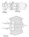
- FIGS. 2a and 2b where the elements homologous to those of FIG.
- the lethal system is composed of three hollow charges 18a, 18b, 18c evenly distributed around the axis of attack (OO ') of the lethal system.
- These hollow charges are arranged in the directions of three planes at 120 ° and their longitudinal axes X'X, are concurrent forward at a point ⁇ of the axis OO 'whose adjustment is predetermined according to the distance d ammunition attack.
- the three hollow charges are identical, they are constituted in a similar manner to that shown in FIG. 1a, of a coating 11, of an explosive charge 12, of a confinement 13 and of a system of simultaneous firing 19 of the three shaped charges.
- the coating 11 is for example made of copper, but other types of material such as aluminum or synthetic products (teflon, etc.) or liquid products (water, etc.) are of interest for the application. It is important that the firing system 19 guarantees good simultaneous operation of the hollow charges to allow the effects sought by the invention as described.
- the firing system 19 can be a known electronic device which simultaneously initiates three detonator primers with a projected layer 20.
- Another embodiment can consist of a pyrotechnic distributor which, starting from a single detonator, goes simultaneously propagate the detonation towards the hollow charges.
- Figure 2c shows after the explosion of the shaped charges 18a, 18b, 18c, the interaction of the jets 16 on the mine explosive.
- Each of the jets develops around the crater it creates, a zone 17 of overpressure, the zone 17 being defined by the intersection with the target 14 of the cone containing the concurrent axes XX 'of the hollow charges and centered on the axis of attack 00 '.
- the zones of overpressure by joining together confine each other and create a surface, subjected to a significant pressure, greater than the sum of the three individual surfaces.
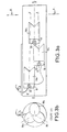
- FIGs 3a and 3b where elements homologous to those of Figures 2a and 2b are shown with the same references, represent a second embodiment of the lethal system according to the invention.
- the shaped charges are placed one behind the other slightly offset in 3 planes 120 ° and their axes of revolution X'X are concurrent at a point ⁇ , located at the front of the system, the position of which is predetermined according to the ammunition attack conditions.
- the ignition system 19 controls the initiator of the detonating primers with projected layers 20 of each shaped charge according to a chronology such as the heads of the jets, preferably constant velocity, simultaneously attacks the explosive charge of the mine.
- the firing systems 19 of each of the shaped charges can be advantageously replaced by a unique firing system produced in the form of the synchronous pyrotechnic distributor shown in Figures 4a and 4b.
- This comprises an input pyrotechnic relay 21 which is put in communication with each of the explosive charges by relay 22 through conduits 23.
- relay 21 is initialized by a primer, the detonation produced propagates through a pyrotechnic network formed by the conduits 23 into which is injected by example an explosive with thermosetting binder.
- These have a length which is determined to maintain a symmetry of the paths of the detonation waves and result in a simultaneous emergence of the detonation at relay output 22.
Landscapes
- Engineering & Computer Science (AREA)
- Chemical & Material Sciences (AREA)
- Combustion & Propulsion (AREA)
- General Engineering & Computer Science (AREA)
- Aviation & Aerospace Engineering (AREA)
- Geophysics And Detection Of Objects (AREA)
- Air Bags (AREA)
- Portable Nailing Machines And Staplers (AREA)
Description
- soit de réduire le volume consacré à la charge pour un type de cible donné,
- soit d'augmenter à volume constant l'agression V2d sur l'explosif de la cible, afin de l'entraíner en détonation, même lorsqu'il est d'un type peu vulnérable.
- une perforation des structures et enveloppes de la cible après franchissement du milieu séparant la munition de la cible à l'instant du fonctionnement, à titre d'exemple le milieu peut être de l'eau,
- une agression importante du chargement explosif de la cible du fait de la combinaison des effets des ondes de chocs pendant la pénétration. Ces jets doivent être concourants pour que leurs effets soient cumulatifs sur une grande surface.
- la satisfaction du critère V2d pour obtenir la destruction par détonation des explosifs de la cible. Lorsque ces explosifs sont peu vulnérables et par conséquent ont des diamètres critiques importants, l'augmentation du critère par le facteur V ne vaut que si d est supérieur à une valeur minimale fonction de l'explosif. Cette valeur est difficilement atteignable avec une seule charge creuse sans aboutir à un calibre de charge prohibitif.
- la figure la représente une vue en coupe d'une munition de type véhicule sous marin suivant l'art antérieur, équipé d'un système létal à une seule charge creuse en position d'attaque vis à vis d'une mine à orin.
- la figure 1b est une vue en coupe, du mode d'action du jet de la charge creuse de la munition représentée à la figure 1a sur l'explosif d'une mine.
- les figures 2a et 2b un premier mode de réalisation d'une munition à multi-charges creuses selon l'invention.
- la figure 2c une vue en coupe du mode d'action des jets des charges creuses de la munition représentée aux figures 2a et 2b.
- les figures 3a et 3b un deuxième mode de réalisation d'une munition à multi-charges creuses selon l'invention.
- les figures 4a et 4b un mode de réalisation d'un distributeur pyrotechnique synchrone utilisable pour la mise à feu du mode de réalisation des figures 2a et 2b.
Suivant un premier mode de réalisation de l'invention qui est représenté aux figures 2a et 2b où les éléments homologues à ceux de la figure la sont représentés avec les mêmes références, le système létal est composé de trois charges creuses 18a, 18b, 18c équiréparties autour de l'axe d'attaque (OO') du système létal. Ces charges creuses sont disposées suivant les directions de trois plans à 120° et leurs axes longitudinaux X'X, sont concourants vers l'avant en un point α de l'axe OO' dont le réglage est prédéterminé en fonction de la distance d'attaque de la munition. A titre d'exemple les trois charges creuses sont identiques, elles sont constituées de façon similaire à celle représentée à la figure 1a, d'un revêtement 11, d'un chargement explosif 12, d'un confinement 13 et d'un système de mise à feu simultanée 19 des trois charges creuses. Le revêtement 11 est par exemple en cuivre, mais d'autres types de matériaux tels que l'aluminium ou des produits synthétiques (téflon...) ou des produits liquides (eau...) présentent un intérêt pour l'application. Il est important que le système de mise à feu 19 garantisse une bonne simultanéité de fonctionnement des charges creuses pour permettre les effets recherchés par l'invention tels qu'ils sont décrits. A titre d'exemple, le système de mise à feu 19 peut être un dispositif électronique connu qui amorce simultanément trois amorces détonateur à couche projetée 20. Un autre mode de réalisation peut consister en un distributeur pyrotechnique qui à partir d'un détonateur unique va propager simultanément la détonation vers les charges creuses.
Claims (12)
- Munition de contre mesure comportant un système létal composé par plusieurs charges creuses réparties autour d'un axe d'attaque (00'), les charges creuses (18a, 18b, 18c) ayant des axes longitudinaux (XX') concourants chaque charge creuse étant destinée à produire un jet de charge creuse (16) agissant concomitamment dans une zone (17) d'une cible (14) avec les autres charges creuses, caractérisée en ce queles axes longitudinaux (XX') sont équirépartis angulairement autour de l'axe d'attaque (00')les charges creuses (18a, 18b, 18c) sont an moins au nombre de trois, la zone (17) étant définie par l'intersection avec la cible (14) du cône contenant les axes concourants (XX') des charges creuses et centré sur l'axe d'attaque (00').
- Munition selon la revendication 1 caractérisée en ce que le système létal comprend un nombre entier N de paquets d'au moins trois charges creuses (18a, 18b, 18c) pour former N zones d'agression de la cible (14).
- Munition selon la revendication 1 caractérisée en ce que les charges creuses (18a,18b,18c) sont au nombre de trois et sont disposées suivant les directions de trois plans à 120°.
- Munition selon la revendication 1 caractérisée en ce que les charges creuses (18a, 18b, 18c) sont placées les une derrière les autres, légèrement décalées.
- Munition selon la revendication 2 caractérisée en ce que les paquets sont placés les uns derrière les autres légèrement décalés.
- Munition selon l'une quelconque des revendications 1 à 3 caractérisée en ce que la mise à feu (19) des charges creuses (18a, 18b, 18c) est assurée par un dispositif synchrone comportant une amorce détonateur à couche projetée par charge creuse.
- Munition selon l'une quelconque des revendications 1 à 4 caractérisée en ce que la mise à feu (19) des charges creuses (18a,18b, 18c) est assurée par un distributeur pyrotechnique (21, 22, 23) initié par une seule amorce.
- Munition selon l'une quelconque des revendications 1 à 5 caractérisée en ce que la mise à feu des charges creuses (18a, 18b, 18c) est assurée par un dispositif pyrotechnique (19) qui assure une chronologie compensant les écarts de trajet des jets.
- Munition selon les revendications 1 à 8 caractérisée en ce que les charges creuses ont un revêtement (11) en métal ou en matériau synthétique ou liquide.
- Munition selon l'une quelconque des revendications 1 à 9 caractérisée en ce qu'elle comprend une charge creuse additionnelle placée devant le système létal.
- Munition selon l'une quelconque des revendications 1 à 8 caractérisée en ce qu'elle comprend une charge explosive placée devant le système létal.
- Utilisation de la munition selon l'une quelconque des revendications 1 à 11 comme véhicule sous marin pour la destruction de mines.
Applications Claiming Priority (3)
| Application Number | Priority Date | Filing Date | Title |
|---|---|---|---|
| FR9807241A FR2779514B1 (fr) | 1998-06-09 | 1998-06-09 | Munition de contre mesure |
| FR9807241 | 1998-06-09 | ||
| PCT/FR1999/001283 WO1999064812A1 (fr) | 1998-06-09 | 1999-06-01 | Munition de contre mesure |
Publications (2)
| Publication Number | Publication Date |
|---|---|
| EP1000312A1 EP1000312A1 (fr) | 2000-05-17 |
| EP1000312B1 true EP1000312B1 (fr) | 2003-10-08 |
Family
ID=9527183
Family Applications (1)
| Application Number | Title | Priority Date | Filing Date |
|---|---|---|---|
| EP99922246A Expired - Lifetime EP1000312B1 (fr) | 1998-06-09 | 1999-06-01 | Munition de contre mesure |
Country Status (6)
| Country | Link |
|---|---|
| EP (1) | EP1000312B1 (fr) |
| DE (1) | DE69911884T2 (fr) |
| DK (1) | DK1000312T3 (fr) |
| ES (1) | ES2209435T3 (fr) |
| FR (1) | FR2779514B1 (fr) |
| WO (1) | WO1999064812A1 (fr) |
Families Citing this family (4)
| Publication number | Priority date | Publication date | Assignee | Title |
|---|---|---|---|---|
| US6540175B1 (en) * | 2001-12-03 | 2003-04-01 | Lockheed Martin Corporation | System for clearing buried and surface mines |
| DE102010051491A1 (de) | 2010-11-15 | 2012-05-16 | Atlas Elektronik Gmbh | Unterwasserfahrzeug und Unterwassersystem mit einem Unterwasserfahrzeug |
| DE102018214824A1 (de) * | 2018-08-31 | 2020-03-05 | Atlas Elektronik Gmbh | Räumgerät und Verfahren zum Neutralisieren eines Kampfmittels unter Wasser |
| DE102019213944A1 (de) * | 2019-09-12 | 2021-03-18 | Atlas Elektronik Gmbh | Unterwasserfahrzeug mit zwei hintereinander angeordneten Hohlladungen |
Family Cites Families (7)
| Publication number | Priority date | Publication date | Assignee | Title |
|---|---|---|---|---|
| US3880103A (en) * | 1972-08-21 | 1975-04-29 | Us Navy | Tethered mine hunting system |
| DE2829002C2 (de) * | 1978-07-01 | 1985-04-04 | Messerschmitt-Bölkow-Blohm GmbH, 8012 Ottobrunn | Gefechtskopf |
| DE2829001C2 (de) * | 1978-07-01 | 1983-09-22 | Messerschmitt-Bölkow-Blohm GmbH, 8000 München | Gefechtskopf mit einem Hauptwirkkörper und einem oder mehreren Nebenwirkkörpern |
| DE3010917C2 (de) * | 1980-03-21 | 1984-03-01 | Messerschmitt-Bölkow-Blohm GmbH, 8000 München | Gefechtskopf mit einer Haupthohlladung und mindestens einer Vorhohlladung |
| DE3626434C3 (de) * | 1986-08-05 | 1994-10-20 | Diehl Gmbh & Co | Verfahren und Einrichtung zum Vernichten großvolumiger Seegrundminen |
| DE3739370A1 (de) * | 1987-11-20 | 1989-06-01 | Diehl Gmbh & Co | Bomblet-gefechtskopf |
| DE19543757C2 (de) * | 1995-11-24 | 1997-09-04 | Diehl Gmbh & Co | Verfahren zur Bekämpfung von Seeminen |
-
1998
- 1998-06-09 FR FR9807241A patent/FR2779514B1/fr not_active Expired - Fee Related
-
1999
- 1999-06-01 DK DK99922246T patent/DK1000312T3/da active
- 1999-06-01 DE DE69911884T patent/DE69911884T2/de not_active Expired - Lifetime
- 1999-06-01 ES ES99922246T patent/ES2209435T3/es not_active Expired - Lifetime
- 1999-06-01 WO PCT/FR1999/001283 patent/WO1999064812A1/fr not_active Ceased
- 1999-06-01 EP EP99922246A patent/EP1000312B1/fr not_active Expired - Lifetime
Also Published As
| Publication number | Publication date |
|---|---|
| ES2209435T3 (es) | 2004-06-16 |
| DE69911884T2 (de) | 2004-09-09 |
| WO1999064812A1 (fr) | 1999-12-16 |
| DK1000312T3 (da) | 2004-02-09 |
| FR2779514B1 (fr) | 2001-01-26 |
| FR2779514A1 (fr) | 1999-12-10 |
| DE69911884D1 (de) | 2003-11-13 |
| EP1000312A1 (fr) | 2000-05-17 |
Similar Documents
| Publication | Publication Date | Title |
|---|---|---|
| EP3102906A1 (fr) | Charge creuse et application pour la separation de deux etages d'un engin aeronautique ou sa neutralisation | |
| EP0438343B1 (fr) | Munition perforante pour des cibles à haute résistance mécanique | |
| EP0221218B1 (fr) | Tête militaire à charges formées montées en tandem | |
| EP0800054B1 (fr) | Projectile dont la charge explosive est déclenchée au moyen d'un désignateur de cible | |
| FR2545923A1 (fr) | Projectile assurant le percage des blindages | |
| FR2844348A1 (fr) | Munitions a bombe d'emploi universel et a cone de charge | |
| EP0084007B1 (fr) | Bombe de pénétration à corps étagé | |
| WO2011023863A1 (fr) | Procédé et système de lancement déporté d'engins tactiques ou stratégiques ayant une phase aérienne, à partir du milieu sous-marin | |
| EP1000312A1 (fr) | Munition de contre mesure | |
| EP1766323B1 (fr) | Projectile, notamment bombe de penetration anti-infrastructure et procede de penetration d'un tel projectile a travers une paroi | |
| EP1521053B1 (fr) | Munition anti bunker | |
| FR2775770A1 (fr) | Obus explosif, canon de projection de l'obus et procede de destruction d'un objet predetermine | |
| EP0943887B1 (fr) | Dispositif de conversion permettant d'obtenir un obus perforant anti structures bétonnées à partir d'un obus explosif et obus perforant obtenu avec un tel dispositif | |
| EP0524232B1 (fr) | Procede de lutte contre les torpilles | |
| EP1302741B1 (fr) | Munition explosive | |
| FR2704052A1 (fr) | Charge formée multiamorçable. | |
| FR2601763A1 (fr) | Projectile sous-calibre de type fleche pour blindages actifs | |
| EP1371935B1 (fr) | Dispositif et muniton de protection d'un véhicule ou d'une plate-forme contre une menace | |
| FR2975482A1 (fr) | Tete militaire anti-infrastructure et projectile equipe d'une telle tete militaire | |
| FR2742539A1 (fr) | Charge explosive a usages multiples, notamment charge de deminage | |
| FR2775769A1 (fr) | Canon, vehicule et procede de destruction d'un objet predetermine | |
| FR2747185A1 (fr) | Projectile generateur d'eclats dont la charge explosive est declenchee au moyen d'un designateur de cible | |
| FR2657157A1 (fr) | Dispositif de correction de courbure d'un trajectoire d'une munition perforante pour des cibles a haute resistance mecanique. | |
| FR2887021A1 (fr) | Kit d'aide a la penetration equipant une bombe, notamment anti-infrastructure, projectile penetrant equipe d'un tel kit, et procede de penetration dans une cible | |
| FR2657158A1 (fr) | Munition perforante pour cible a haute resistance mecanique. |
Legal Events
| Date | Code | Title | Description |
|---|---|---|---|
| PUAI | Public reference made under article 153(3) epc to a published international application that has entered the european phase |
Free format text: ORIGINAL CODE: 0009012 |
|
| 17P | Request for examination filed |
Effective date: 19991222 |
|
| AK | Designated contracting states |
Kind code of ref document: A1 Designated state(s): DE DK ES GB IT NL SE |
|
| 17Q | First examination report despatched |
Effective date: 20020326 |
|
| GRAH | Despatch of communication of intention to grant a patent |
Free format text: ORIGINAL CODE: EPIDOS IGRA |
|
| GRAS | Grant fee paid |
Free format text: ORIGINAL CODE: EPIDOSNIGR3 |
|
| GRAA | (expected) grant |
Free format text: ORIGINAL CODE: 0009210 |
|
| AK | Designated contracting states |
Kind code of ref document: B1 Designated state(s): DE DK ES GB IT NL SE |
|
| REG | Reference to a national code |
Ref country code: GB Ref legal event code: FG4D Free format text: NOT ENGLISH |
|
| REF | Corresponds to: |
Ref document number: 69911884 Country of ref document: DE Date of ref document: 20031113 Kind code of ref document: P |
|
| REG | Reference to a national code |
Ref country code: SE Ref legal event code: TRGR |
|
| REG | Reference to a national code |
Ref country code: DK Ref legal event code: T3 |
|
| GBT | Gb: translation of ep patent filed (gb section 77(6)(a)/1977) |
Effective date: 20040119 |
|
| REG | Reference to a national code |
Ref country code: ES Ref legal event code: FG2A Ref document number: 2209435 Country of ref document: ES Kind code of ref document: T3 |
|
| PLBE | No opposition filed within time limit |
Free format text: ORIGINAL CODE: 0009261 |
|
| STAA | Information on the status of an ep patent application or granted ep patent |
Free format text: STATUS: NO OPPOSITION FILED WITHIN TIME LIMIT |
|
| 26N | No opposition filed |
Effective date: 20040709 |
|
| PGFP | Annual fee paid to national office [announced via postgrant information from national office to epo] |
Ref country code: ES Payment date: 20120726 Year of fee payment: 14 |
|
| PGFP | Annual fee paid to national office [announced via postgrant information from national office to epo] |
Ref country code: DE Payment date: 20130529 Year of fee payment: 15 Ref country code: DK Payment date: 20130611 Year of fee payment: 15 Ref country code: GB Payment date: 20130529 Year of fee payment: 15 Ref country code: SE Payment date: 20130612 Year of fee payment: 15 |
|
| PGFP | Annual fee paid to national office [announced via postgrant information from national office to epo] |
Ref country code: NL Payment date: 20130608 Year of fee payment: 15 Ref country code: IT Payment date: 20130620 Year of fee payment: 15 |
|
| REG | Reference to a national code |
Ref country code: DE Ref legal event code: R119 Ref document number: 69911884 Country of ref document: DE |
|
| REG | Reference to a national code |
Ref country code: DK Ref legal event code: EBP Effective date: 20140630 |
|
| REG | Reference to a national code |
Ref country code: NL Ref legal event code: V1 Effective date: 20150101 |
|
| PG25 | Lapsed in a contracting state [announced via postgrant information from national office to epo] |
Ref country code: SE Free format text: LAPSE BECAUSE OF NON-PAYMENT OF DUE FEES Effective date: 20140602 |
|
| REG | Reference to a national code |
Ref country code: SE Ref legal event code: EUG |
|
| GBPC | Gb: european patent ceased through non-payment of renewal fee |
Effective date: 20140601 |
|
| PG25 | Lapsed in a contracting state [announced via postgrant information from national office to epo] |
Ref country code: NL Free format text: LAPSE BECAUSE OF NON-PAYMENT OF DUE FEES Effective date: 20150101 |
|
| REG | Reference to a national code |
Ref country code: DE Ref legal event code: R119 Ref document number: 69911884 Country of ref document: DE Effective date: 20150101 |
|
| PG25 | Lapsed in a contracting state [announced via postgrant information from national office to epo] |
Ref country code: IT Free format text: LAPSE BECAUSE OF NON-PAYMENT OF DUE FEES Effective date: 20140601 Ref country code: DE Free format text: LAPSE BECAUSE OF NON-PAYMENT OF DUE FEES Effective date: 20150101 |
|
| PG25 | Lapsed in a contracting state [announced via postgrant information from national office to epo] |
Ref country code: GB Free format text: LAPSE BECAUSE OF NON-PAYMENT OF DUE FEES Effective date: 20140601 |
|
| PG25 | Lapsed in a contracting state [announced via postgrant information from national office to epo] |
Ref country code: DK Free format text: LAPSE BECAUSE OF NON-PAYMENT OF DUE FEES Effective date: 20140630 |
|
| REG | Reference to a national code |
Ref country code: ES Ref legal event code: FD2A Effective date: 20160128 |
|
| PG25 | Lapsed in a contracting state [announced via postgrant information from national office to epo] |
Ref country code: ES Free format text: LAPSE BECAUSE OF NON-PAYMENT OF DUE FEES Effective date: 20140602 |