EP1000691A2 - Superfinition de composants d'implants polymériques - Google Patents
Superfinition de composants d'implants polymériques Download PDFInfo
- Publication number
- EP1000691A2 EP1000691A2 EP99309062A EP99309062A EP1000691A2 EP 1000691 A2 EP1000691 A2 EP 1000691A2 EP 99309062 A EP99309062 A EP 99309062A EP 99309062 A EP99309062 A EP 99309062A EP 1000691 A2 EP1000691 A2 EP 1000691A2
- Authority
- EP
- European Patent Office
- Prior art keywords
- component
- tool
- contour
- cutting tool
- micrometers
- Prior art date
- Legal status (The legal status is an assumption and is not a legal conclusion. Google has not performed a legal analysis and makes no representation as to the accuracy of the status listed.)
- Withdrawn
Links
- 239000007943 implant Substances 0.000 title claims description 29
- 238000005520 cutting process Methods 0.000 claims abstract description 85
- 238000000034 method Methods 0.000 claims abstract description 45
- 229910003460 diamond Inorganic materials 0.000 claims abstract description 31
- 239000010432 diamond Substances 0.000 claims abstract description 31
- 210000000988 bone and bone Anatomy 0.000 claims abstract description 15
- 238000002513 implantation Methods 0.000 claims abstract description 14
- 239000002245 particle Substances 0.000 claims abstract description 7
- 239000004699 Ultra-high molecular weight polyethylene Substances 0.000 claims abstract description 5
- 229920000785 ultra high molecular weight polyethylene Polymers 0.000 claims abstract description 5
- 239000000463 material Substances 0.000 claims description 14
- 238000001727 in vivo Methods 0.000 claims description 3
- 150000001875 compounds Chemical class 0.000 claims description 2
- 238000010408 sweeping Methods 0.000 claims 1
- 230000003746 surface roughness Effects 0.000 abstract description 9
- 206010024769 Local reaction Diseases 0.000 abstract 1
- 230000000694 effects Effects 0.000 abstract 1
- 229920000642 polymer Polymers 0.000 abstract 1
- 230000009885 systemic effect Effects 0.000 abstract 1
- 238000001816 cooling Methods 0.000 description 4
- 238000001356 surgical procedure Methods 0.000 description 4
- 230000015572 biosynthetic process Effects 0.000 description 3
- 238000004519 manufacturing process Methods 0.000 description 3
- 229910000831 Steel Inorganic materials 0.000 description 2
- 229920010741 Ultra High Molecular Weight Polyethylene (UHMWPE) Polymers 0.000 description 2
- 230000002411 adverse Effects 0.000 description 2
- 238000013459 approach Methods 0.000 description 2
- 238000010586 diagram Methods 0.000 description 2
- 238000007731 hot pressing Methods 0.000 description 2
- 230000002706 hydrostatic effect Effects 0.000 description 2
- 238000005259 measurement Methods 0.000 description 2
- 239000010959 steel Substances 0.000 description 2
- 230000000153 supplemental effect Effects 0.000 description 2
- 208000006386 Bone Resorption Diseases 0.000 description 1
- 229910000997 High-speed steel Inorganic materials 0.000 description 1
- 206010061218 Inflammation Diseases 0.000 description 1
- SMNRFWMNPDABKZ-WVALLCKVSA-N [[(2R,3S,4R,5S)-5-(2,6-dioxo-3H-pyridin-3-yl)-3,4-dihydroxyoxolan-2-yl]methoxy-hydroxyphosphoryl] [[[(2R,3S,4S,5R,6R)-4-fluoro-3,5-dihydroxy-6-(hydroxymethyl)oxan-2-yl]oxy-hydroxyphosphoryl]oxy-hydroxyphosphoryl] hydrogen phosphate Chemical compound OC[C@H]1O[C@H](OP(O)(=O)OP(O)(=O)OP(O)(=O)OP(O)(=O)OC[C@H]2O[C@H]([C@H](O)[C@@H]2O)C2C=CC(=O)NC2=O)[C@H](O)[C@@H](F)[C@@H]1O SMNRFWMNPDABKZ-WVALLCKVSA-N 0.000 description 1
- 230000003190 augmentative effect Effects 0.000 description 1
- 230000009286 beneficial effect Effects 0.000 description 1
- 230000024279 bone resorption Effects 0.000 description 1
- 238000006243 chemical reaction Methods 0.000 description 1
- 238000013016 damping Methods 0.000 description 1
- 230000032798 delamination Effects 0.000 description 1
- 230000001627 detrimental effect Effects 0.000 description 1
- 238000007730 finishing process Methods 0.000 description 1
- 239000010438 granite Substances 0.000 description 1
- 238000000227 grinding Methods 0.000 description 1
- 230000004054 inflammatory process Effects 0.000 description 1
- 238000002955 isolation Methods 0.000 description 1
- 210000003127 knee Anatomy 0.000 description 1
- 238000003754 machining Methods 0.000 description 1
- 238000003801 milling Methods 0.000 description 1
- 230000003287 optical effect Effects 0.000 description 1
- 230000000399 orthopedic effect Effects 0.000 description 1
- 238000005498 polishing Methods 0.000 description 1
- 238000007493 shaping process Methods 0.000 description 1
- 210000001519 tissue Anatomy 0.000 description 1
Images



Classifications
-
- A—HUMAN NECESSITIES
- A61—MEDICAL OR VETERINARY SCIENCE; HYGIENE
- A61F—FILTERS IMPLANTABLE INTO BLOOD VESSELS; PROSTHESES; DEVICES PROVIDING PATENCY TO, OR PREVENTING COLLAPSING OF, TUBULAR STRUCTURES OF THE BODY, e.g. STENTS; ORTHOPAEDIC, NURSING OR CONTRACEPTIVE DEVICES; FOMENTATION; TREATMENT OR PROTECTION OF EYES OR EARS; BANDAGES, DRESSINGS OR ABSORBENT PADS; FIRST-AID KITS
- A61F2/00—Filters implantable into blood vessels; Prostheses, i.e. artificial substitutes or replacements for parts of the body; Appliances for connecting them with the body; Devices providing patency to, or preventing collapsing of, tubular structures of the body, e.g. stents
- A61F2/02—Prostheses implantable into the body
- A61F2/30—Joints
- A61F2/30767—Special external or bone-contacting surface, e.g. coating for improving bone ingrowth
-
- B—PERFORMING OPERATIONS; TRANSPORTING
- B23—MACHINE TOOLS; METAL-WORKING NOT OTHERWISE PROVIDED FOR
- B23B—TURNING; BORING
- B23B27/00—Tools for turning or boring machines; Tools of a similar kind in general; Accessories therefor
- B23B27/14—Cutting tools of which the bits or tips or cutting inserts are of special material
- B23B27/18—Cutting tools of which the bits or tips or cutting inserts are of special material with cutting bits or tips or cutting inserts rigidly mounted, e.g. by brazing
- B23B27/20—Cutting tools of which the bits or tips or cutting inserts are of special material with cutting bits or tips or cutting inserts rigidly mounted, e.g. by brazing with diamond bits or cutting inserts
-
- A—HUMAN NECESSITIES
- A61—MEDICAL OR VETERINARY SCIENCE; HYGIENE
- A61F—FILTERS IMPLANTABLE INTO BLOOD VESSELS; PROSTHESES; DEVICES PROVIDING PATENCY TO, OR PREVENTING COLLAPSING OF, TUBULAR STRUCTURES OF THE BODY, e.g. STENTS; ORTHOPAEDIC, NURSING OR CONTRACEPTIVE DEVICES; FOMENTATION; TREATMENT OR PROTECTION OF EYES OR EARS; BANDAGES, DRESSINGS OR ABSORBENT PADS; FIRST-AID KITS
- A61F2/00—Filters implantable into blood vessels; Prostheses, i.e. artificial substitutes or replacements for parts of the body; Appliances for connecting them with the body; Devices providing patency to, or preventing collapsing of, tubular structures of the body, e.g. stents
- A61F2/02—Prostheses implantable into the body
- A61F2/30—Joints
- A61F2/3094—Designing or manufacturing processes
-
- A—HUMAN NECESSITIES
- A61—MEDICAL OR VETERINARY SCIENCE; HYGIENE
- A61F—FILTERS IMPLANTABLE INTO BLOOD VESSELS; PROSTHESES; DEVICES PROVIDING PATENCY TO, OR PREVENTING COLLAPSING OF, TUBULAR STRUCTURES OF THE BODY, e.g. STENTS; ORTHOPAEDIC, NURSING OR CONTRACEPTIVE DEVICES; FOMENTATION; TREATMENT OR PROTECTION OF EYES OR EARS; BANDAGES, DRESSINGS OR ABSORBENT PADS; FIRST-AID KITS
- A61F2/00—Filters implantable into blood vessels; Prostheses, i.e. artificial substitutes or replacements for parts of the body; Appliances for connecting them with the body; Devices providing patency to, or preventing collapsing of, tubular structures of the body, e.g. stents
- A61F2/02—Prostheses implantable into the body
- A61F2/30—Joints
- A61F2/32—Joints for the hip
- A61F2/34—Acetabular cups
-
- A—HUMAN NECESSITIES
- A61—MEDICAL OR VETERINARY SCIENCE; HYGIENE
- A61F—FILTERS IMPLANTABLE INTO BLOOD VESSELS; PROSTHESES; DEVICES PROVIDING PATENCY TO, OR PREVENTING COLLAPSING OF, TUBULAR STRUCTURES OF THE BODY, e.g. STENTS; ORTHOPAEDIC, NURSING OR CONTRACEPTIVE DEVICES; FOMENTATION; TREATMENT OR PROTECTION OF EYES OR EARS; BANDAGES, DRESSINGS OR ABSORBENT PADS; FIRST-AID KITS
- A61F2/00—Filters implantable into blood vessels; Prostheses, i.e. artificial substitutes or replacements for parts of the body; Appliances for connecting them with the body; Devices providing patency to, or preventing collapsing of, tubular structures of the body, e.g. stents
- A61F2/02—Prostheses implantable into the body
- A61F2/30—Joints
- A61F2/38—Joints for elbows or knees
- A61F2/389—Tibial components
-
- A—HUMAN NECESSITIES
- A61—MEDICAL OR VETERINARY SCIENCE; HYGIENE
- A61F—FILTERS IMPLANTABLE INTO BLOOD VESSELS; PROSTHESES; DEVICES PROVIDING PATENCY TO, OR PREVENTING COLLAPSING OF, TUBULAR STRUCTURES OF THE BODY, e.g. STENTS; ORTHOPAEDIC, NURSING OR CONTRACEPTIVE DEVICES; FOMENTATION; TREATMENT OR PROTECTION OF EYES OR EARS; BANDAGES, DRESSINGS OR ABSORBENT PADS; FIRST-AID KITS
- A61F2/00—Filters implantable into blood vessels; Prostheses, i.e. artificial substitutes or replacements for parts of the body; Appliances for connecting them with the body; Devices providing patency to, or preventing collapsing of, tubular structures of the body, e.g. stents
- A61F2/02—Prostheses implantable into the body
- A61F2/30—Joints
- A61F2/30767—Special external or bone-contacting surface, e.g. coating for improving bone ingrowth
- A61F2/30771—Special external or bone-contacting surface, e.g. coating for improving bone ingrowth applied in original prostheses, e.g. holes or grooves
- A61F2002/30838—Microstructures
-
- A—HUMAN NECESSITIES
- A61—MEDICAL OR VETERINARY SCIENCE; HYGIENE
- A61F—FILTERS IMPLANTABLE INTO BLOOD VESSELS; PROSTHESES; DEVICES PROVIDING PATENCY TO, OR PREVENTING COLLAPSING OF, TUBULAR STRUCTURES OF THE BODY, e.g. STENTS; ORTHOPAEDIC, NURSING OR CONTRACEPTIVE DEVICES; FOMENTATION; TREATMENT OR PROTECTION OF EYES OR EARS; BANDAGES, DRESSINGS OR ABSORBENT PADS; FIRST-AID KITS
- A61F2/00—Filters implantable into blood vessels; Prostheses, i.e. artificial substitutes or replacements for parts of the body; Appliances for connecting them with the body; Devices providing patency to, or preventing collapsing of, tubular structures of the body, e.g. stents
- A61F2/02—Prostheses implantable into the body
- A61F2/30—Joints
- A61F2/30767—Special external or bone-contacting surface, e.g. coating for improving bone ingrowth
- A61F2002/30934—Special articulating surfaces
-
- Y—GENERAL TAGGING OF NEW TECHNOLOGICAL DEVELOPMENTS; GENERAL TAGGING OF CROSS-SECTIONAL TECHNOLOGIES SPANNING OVER SEVERAL SECTIONS OF THE IPC; TECHNICAL SUBJECTS COVERED BY FORMER USPC CROSS-REFERENCE ART COLLECTIONS [XRACs] AND DIGESTS
- Y10—TECHNICAL SUBJECTS COVERED BY FORMER USPC
- Y10T—TECHNICAL SUBJECTS COVERED BY FORMER US CLASSIFICATION
- Y10T29/00—Metal working
- Y10T29/49—Method of mechanical manufacture
-
- Y—GENERAL TAGGING OF NEW TECHNOLOGICAL DEVELOPMENTS; GENERAL TAGGING OF CROSS-SECTIONAL TECHNOLOGIES SPANNING OVER SEVERAL SECTIONS OF THE IPC; TECHNICAL SUBJECTS COVERED BY FORMER USPC CROSS-REFERENCE ART COLLECTIONS [XRACs] AND DIGESTS
- Y10—TECHNICAL SUBJECTS COVERED BY FORMER USPC
- Y10T—TECHNICAL SUBJECTS COVERED BY FORMER US CLASSIFICATION
- Y10T82/00—Turning
- Y10T82/10—Process of turning
-
- Y—GENERAL TAGGING OF NEW TECHNOLOGICAL DEVELOPMENTS; GENERAL TAGGING OF CROSS-SECTIONAL TECHNOLOGIES SPANNING OVER SEVERAL SECTIONS OF THE IPC; TECHNICAL SUBJECTS COVERED BY FORMER USPC CROSS-REFERENCE ART COLLECTIONS [XRACs] AND DIGESTS
- Y10—TECHNICAL SUBJECTS COVERED BY FORMER USPC
- Y10T—TECHNICAL SUBJECTS COVERED BY FORMER US CLASSIFICATION
- Y10T82/00—Turning
- Y10T82/25—Lathe
- Y10T82/2502—Lathe with program control
Definitions
- the invention relates generally to the surface finishing of implantable prosthetic components. More particularly, the invention relates to surface finishing of an articulating or contacting surface of a polymeric orthopedic prosthesis.
- components that have varying surface roughness characteristics.
- components such as liners, cups, stems, heads, trays and shells
- surfaces texture or roughness characteristics tend to produce wear debris that is shed from the components during a "breaking-in” or “wearing-in” period that occurs due to, for example, micromotion at a shell to liner interface, or due to articulation at a liner to head interface.
- This invention provides a finished implantable polymeric prosthetic joint or bone component having a superior surface finish, or "super finish", and a method for fabricating the component.
- the joint or bone component can be a cup, shell, tray insert, stem, liner or head, or other component which has a face that, once implanted or during implantation, is a surface which is to be subjected to a surface-to-surface contact, or motion.
- the joint or bone component is prepared by subjecting the component to a turning movement against a surface cutting tool such that the component has a circularly symmetric or radially symmetric finish region with an as-machined cut surface finish substantially smoother than about 0.5 micrometers.
- the joint or bone component once prepared in accordance with the present invention, has a visually smooth contact region and is matable with a similarly contoured implant component for sliding or micromovement therebetween.
- the implantable polymeric prosthetic joint or bone component has a two-dimensional surface contour with an as-machined surface profile in a cross direction with peak to valley surface smoothness effective to achieve in vivo particle generation at a residual (e.g., asymptotically flat) level or rate.
- Also provided by the present invention is a method of preparing the implantable prosthetic joint or bone component.
- the method comprises the steps of placing the component in a mounting, such as a chuck or collet, on a turning machine, such as a lathe, for rotation against a replaceable or resharpenable cutting tool, and rotationally cutting the face of the component with a diamond cutting tool having a predetermined shape, geometry and sharpness effective to form a cut surface contour with waviness under 0.5 micrometers.
- the cutting tool may be brazed into a tool tip insert such as a steel or carbide tip insert, or clamped onto a tool holder for indexable tooling.
- the component is rotated while the cutting tool is fed across a controlled R, X & Z feed path one or more times, with each time constituting one "pass.”
- Each pass removes material from the surface of the component, and the diamond cutter tool path forms a final profile.
- the position of the cutting tool and/or the total number of passes of the cutting tool may be controlled by computer.
- the method of the present invention also contemplates steps of cooling the cutting edge of the tool and/or removing swarf while the cutting of the component occurs.
- the method concludes when the surface attains the desired shape, with a surface finish substantially smoother than 0.5 micrometers and a variation of contour waviness less than or equal to 0.5 micrometers.
- the method of the present invention preferably provides a smooth surface finish with excursions or variations from a nominal flat or curved surface profile lying below a threshold which is 0.05 and 0.10 micrometers.
- the cutting tool may be rotated to fly cut a surface of the component while it is held stationary or translated.
- the turning machine carries the component on an air-bearing, and the tool compound may operate with air or hydrostatic slides and damping to minimize vibration, or to prevent transfer of vibrational artifacts to the surface finish of the component.
- FIG. 1 A process for preparing an implant component in accordance with the present invention is shown in the flow diagram of FIG. 1.
- an implant component is mounted on a machine such as a turning lathe.
- Suitable implant components for mounting include a joint or bone prosthesis component such as a cup, shell, tray, stem, liner or head or any other implant component which has a face that possesses radial symmetry in a region, and that is a flat or curved surface which is to be subjected to contact or motion once implanted or during implantation.
- Particularly suitable implant components are those made of ultra-high molecular weight polyethylene (UHMWPE) and include, but are not limited to, acetabular liners for hip prostheses and tibial trays, stems of tibial plateaus for knee prostheses.
- UHMWPE ultra-high molecular weight polyethylene
- Suitable turning machines include horizontal or vertical lathes and, in particular, a horizontal, chucking-type turret lathe which accommodates one or more surface cutting tools. Milling machines or mill/turning machines may also be used for the practice of the invention.
- the machine may be adapted to operate with air bearings to move effectively isolate the implant component from mechanical vibration during the machining process.
- a turning machine is used that is adapted with air bearings and allows for a positioning tolerance of within 0.005 millimeters, with an electronic feed with ball screws to effectively eliminate backlash.
- the implant component is mounted via means capable of firmly grasping and holding, but not deforming, implant components that are made of various materials and have various dimensions.
- Some of the suitable means for mounting the implant component include a collet or a chuck, which is preferably formed with a receiving shape closely adapted to be the outside profile of the component, and which may be configured for vacuum clamping in a production setting.
- the means for mounting the implant component may be operated via manual or automated control. On a lathe, the implant component is mounted on the turning axis of the machine while on a fly cutter, it is mounted along the axis of the tool movement.
- the process continues to the second step 12.
- the component comes into rotational contact with a cutting tool or tools.
- the contacting of the cutting tool(s) and the component may be accomplished several ways, including, but not limited to, rotating the component and feeding the tool against the component or rotating the cutting tool(s) to fly cut a component which is held stationary or translated.
- the cutting tool(s) of the turning machine should be made of material(s), and should have a shape, a geometry and a sharpness, and should be rotated at a rate sufficient to achieve the aforesaid surface profile and surface finish for the component being cut.
- applicant has found a single diamond tool to suffice for the finish cut and for rough cuts if any of these are necessary.
- more cutting tools may be provided, and if more than one cutting tool is provided, these may include tools of high speed steel, carbide or the like for rough cutting.
- the final tool is a natural or synthetic diamond cutting tool.
- the diamond cutting tool may be brazed into a tool tip insert such as a steel or carbide insert.
- the cutting tool(s) should either be resharpenable or replaceable after a predetermined number of cuts or a predetermined amount of cutting time or when the tools(s) have achieved a predetermined level of dullness, and may be adapted to be easily retrofitted into existing turning machines.
- the diamond cutting tools for use in the present invention have sharpness and radii of the cutting edge that allow removal of up to ten or twenty mils in a pass while minimizing the appearance of feed lines on the cut component.
- Each carbide cutting tool that is provided should have a sharp profile and a cutting radius.
- the sharpness and radius of each of the cutting tools may differ from the other cutting tools, with the sharpnesses being effective to form one or more rough cuts to finish the component sufficiently to allow the diamond to cut the profile in a single pass.
- the rough and finish cuts may both be performed with the diamond tool.
- the cutting tool(s) or the component, whichever is being rotated should be rotated at a rate over 1000 revolutions per minute, and is preferably rotated at 3500 revolutions per minute or more, with an effective cross feed rate.
- the third step 14 of the process is the cutting and shaping of the component by advancing the cutting tool(s) to form the desired surface profile.
- the cutting tool(s) are fed across a multi-axis, controlled feed path a predetermined number of times (with each time constituting one "pass") in order to remove material from the surface of the component so as to achieve a final, predetermined surface profile on the component.
- the feed path is an R, X & Z feed path.
- the tool cross feed is slow, and the amount of time that elapses for cutting a quasi-spherical surface, or for the final cutting tool to complete its feed path, per pass, is about one minute, but may be set to be more or less time via numerical control. It should also be mentioned that manual or CNC-controlled R- ⁇ type machines may also be employed. In this case, the tool may pivot in an arc to form the desired surface contour rather than interpolating the profile as a series of steps.
- the component is preferably cut so as to have a surface finish substantially free of tool marks visible to the unaided eye, for example, wherein the surface waviness of the component is under about 0.5 micrometers.
- the surface finish or roughness of the component should be substantially smoother than 0.5 micrometers, and is preferably a surface smoothness of approximately 0.05 to 0.10 micrometers.
- Such surface waviness and surface roughness characteristics may be attained by providing numerical control of the position of the cutting tool, and, if necessary, augmenting the total number of passes the cutting tool makes on the component.
- the numerical control is provided by computer in a way known in the art.
- a component may be cut by one or more carbide tools and a diamond cutting tool, or by only a diamond tool in accordance with the process of FIG. 1, the diamond cutting tool should always be the last of the tools to contact the face of the component in order to provide the desired low surface roughness and waviness characteristics.
- the third step 14 of the process may also include vacuum and/or cooling systems, for example, to cool the cutting surface and/or to remove swarf that accumulates during the cutting process.
- vacuum and cooling systems are adapted to perform in conjunction with the cutting tool(s) and the turning machine in ways generally known in the art.
- an implantable polymeric prosthetic joint or bone component is so as to have a two-dimensional surface contour with an as-machined surface profile in a cross direction with peak to valley surface smoothness effective to achieve in vivo particle generation at a residual level. That is, when placed in use, a moving component generates wear particles due to small irregularities of the opposing surfaces rubbing against each other. Typically, such particles are initially generated at a high rate, primarily from the irregularities of the polymeric components, and as the surfaces become more regular or better fitting, wear particles are generated at a lower or residual rate, which may approach a low or zero level. The present invention achieves this residual level with an as-machined surface of the polymeric component.
- FIGS. 2, 2A and 3 two exemplary implant components that may be prepared in accordance with the three-step process of FIG. 1 are shown.
- the exemplary component 16 of FIGS. 2 and 2A is an insert for a tibial tray and the exemplary component 16' of FIG. 3 is a liner for an acetabular component.
- Other implant components that may be prepared in accordance with the process of FIG. 1 include a joint or bone component such as a cup, shell, tray, stem, or head or any other implant component which has a face that, once implanted or during implantation, is a flat or curved surface which is to be subjected to contact or motion, including micro-motion such as that which occurs between nominally stationary, but contacting surfaces.
- implant components prepared in accordance with the process of FIG. 1 are made of ultra-high molecular weight polyethylene (UHMWPE).
- UHMWPE ultra-high molecular weight polyethylene
- the insert 16 has an anterior surface 18 and a posterior surface 20 and also has medial and lateral surfaces or sides such as 22.
- the implant has a superior face 24 of curved aspect that will be subjected to contact or motion when utilized in ways known in the art during, and subsequent to, the implantation of a hip prosthesis, and that face may be super finished in accordance with the process of FIG. 1 such that the face has a surface finish substantially free of tool mark waviness visible to the unaided eye wherein its surface waviness is under about 0.5 micrometers and its surface finish has a surface roughness substantially less than 0.5 micrometers, preferably less than approximately 0.05 to 0.10 micrometers.
- an inferior surface 25 of the insert 16 may be fly cut to a flat non-wavy super finished profile.
- the liner 16' is a concave shell of bearing material having an interior face 25' and an exterior surface 24'. As is generally known to those in the art, the liner 16' fits within a generally metallic external support or acetabular component (not shown), while a ball of a corresponding femoral component of the prosthesis (not shown) bears against the interior surface 25' of the liner.
- the interior and exterior surfaces 25', 24' of the liner 16' will be subjected to contact or motion when utilized in ways known in the art during, and subsequent to, the implantation of a hip prosthesis, and these faces may be super finished in accordance with the process of FIG.
- the faces have a surface finish substantially free of tool mark waviness visible to the unaided eye wherein its surface waviness is under about 0.5 micrometers and its surface finish has a surface roughness substantially less than 0.5 micrometers, preferably less than approximately 0.05 to 0.10 micrometers.
- this turning machine 24 is a horizontal, chucking-type, turret lathe adapted to be provided with a plurality of cutting tools.
- the lathe 24 includes a tool feed carriage 26 and a turning motor 28 with a component holding means 30.
- the component holding means 30 may be provided as a chuck or a collet or any other suitable means known in the art to hold an implant component without deforming the component.
- it is a collet or chuck with a fitted recess sized for gripping and supporting the particular component.
- the tool feed carriage 26 further includes a turret-type tool holder 32 and a tool feed compound 34 for one or more cutting tools 36, and is adapted to move along a z- or longitudinal axis 38 that is parallel to the turning axis of the engine 28 and also to move along a cross-feed direction.
- a turret-type tool holder 32 and a tool feed compound 34 for one or more cutting tools 36 is adapted to move along a z- or longitudinal axis 38 that is parallel to the turning axis of the engine 28 and also to move along a cross-feed direction.
- Any or all of the components of the turret lathe 24 are adapted to be numerically controlled by computer (not shown).
- the turret lathe 24 may also be adapted to include vacuum and/or cooling systems to remove swarf and heat generated by the cutting process.
- FIG. 5 a top view of the tool holding assembly 32 of FIG. 4 is shown.
- a four-way tool turret 32 is shown having four cutting tools 36.
- the cutting tools 36 are carbide tools 36A having sharpnesses, radii and rake angles appropriate for the material and shape being cut.
- the invention may be practiced using only the one diamond cutting tool 36B, or with a total number of cutting tools 36 that is greater or less than four while still being able to provide the requisite super finishing characteristics to implant components.
- the carbide tools if provided, may be identical tools, with redundant ones serving as replacements to minimize set-up time when one becomes dull; or may be configured to make successively finer passes to reach the desired finish.
- Super finishing characteristics are preferably achieved, through computerized numerical control, by cutting the component with one or a plurality of cutting tools 36 such that the component has a circularly symmetric finish region on a surface of the component that is to be subjected to motion and/or sliding against another implant component. If the component is not sufficiently smooth or centered in its raw (e.g. cast, extruded or molded) state, it is first cut to a predetermined preliminary contour at which point a different one of the plurality of cutting tools may be moved to cut the surface of the component. Each cutting tool 36 may have a different sharpness and radius. Moreover, a diamond cutting tool 36B should be the last cutting tool to be introduced to the surface of the component, wherein it removes material from the preliminary cut surface to form the final super finished machine cut surface.
- Nanoform 200 model is a two-axis, computer controlled, ultra-precision contouring machine which may be used with diamond cutting tools to form optical quality surfaces on a wide range of materials and which also may be equipped with a high-speed grinding attachment to form precision molds having high quality surfaces.
- the Nanoform 200 model is built on a granite base and utilizes a passive vibration isolation system.
- High stiffness hydrostatic oil bearing slideways are arranged in a "T" configuration such that the X-axis (spindle) slide represents the cross-arm of the "T” and the Z-axis (tool holding) slide represents the stem of the "T.”
- the Nanoform 200 model is available with a digital signal processor based control system which provides a one nanometer programming resolution, sub-count feedback signal interpolation and industry standard M and G code programming format.
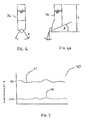
- the tool has a shank length, L, of between about 70 millimeters to about 100 millimeters and an arc, A, of about 140°.
- the exemplary tool has a rake angle, ⁇ , of about 5° to about 15° and a front clearance angle, ⁇ , of about 30°.
- ⁇ rake angle
- ⁇ front clearance angle
- the graphical representation 40 notes the surface waviness, in micrometers, of prior art implant components and implant components as they relate to baseline variations of 0.5 and 0.05 micrometers.
- Prior art implant components have machine cut surface waviness measurements 41 that are greater than about the 0.5 micrometer baseline which corresponds to surface texture that is visible to the unaided eye. These components may be polished to reduce roughness to below .4 micrometers, but they will retain this pattern of wavy cut lines.
- the schematic representation 43 shows a baseline 44 that corresponds to an ideal flat or spherical surface contour of an implanted component.
- Curve 48 shows the actual profile and resulting machine ridges produced during a surface cutting and finishing process of the prior art.
- the prior art residual machine ridges 48 depart greatly from the ideal contour baseline 44 during one period 50 (corresponding to the feed per rotation of the component/tool). Similarly large excursions may occur over even shorter intervals when the prior art cutting tool has waviness or wear irregularities.
- small residual cut artifacts 46 are left by the super finishing cutting process of the present invention which depart from the ideal baseline 44 by a very small amount. That amount of departure is substantially less than 0.5 micrometers, and is not visible to the unaided eye. Surface roughness is similarly very low, even without secondary polishing.
Landscapes
- Health & Medical Sciences (AREA)
- Engineering & Computer Science (AREA)
- Vascular Medicine (AREA)
- Life Sciences & Earth Sciences (AREA)
- Transplantation (AREA)
- Cardiology (AREA)
- Biomedical Technology (AREA)
- Heart & Thoracic Surgery (AREA)
- Orthopedic Medicine & Surgery (AREA)
- Oral & Maxillofacial Surgery (AREA)
- Animal Behavior & Ethology (AREA)
- General Health & Medical Sciences (AREA)
- Public Health (AREA)
- Veterinary Medicine (AREA)
- Mechanical Engineering (AREA)
- Prostheses (AREA)
Applications Claiming Priority (2)
| Application Number | Priority Date | Filing Date | Title |
|---|---|---|---|
| US193335 | 1994-02-08 | ||
| US19333598A | 1998-11-16 | 1998-11-16 |
Publications (2)
| Publication Number | Publication Date |
|---|---|
| EP1000691A2 true EP1000691A2 (fr) | 2000-05-17 |
| EP1000691A3 EP1000691A3 (fr) | 2002-07-03 |
Family
ID=22713227
Family Applications (1)
| Application Number | Title | Priority Date | Filing Date |
|---|---|---|---|
| EP99309062A Withdrawn EP1000691A3 (fr) | 1998-11-16 | 1999-11-15 | Superfinition de composants d'implants polymériques |
Country Status (2)
| Country | Link |
|---|---|
| US (1) | US6748834B2 (fr) |
| EP (1) | EP1000691A3 (fr) |
Families Citing this family (8)
| Publication number | Priority date | Publication date | Assignee | Title |
|---|---|---|---|---|
| US7556763B2 (en) * | 1999-12-08 | 2009-07-07 | Diamicron, Inc. | Method of making components for prosthetic joints |
| FR2904930B1 (fr) * | 2006-08-18 | 2012-08-17 | Advanced Technical Fabrication | Cotyle a double mobilite a moyens anti-usure |
| US20100125335A1 (en) * | 2008-11-20 | 2010-05-20 | Daley Robert J | Methods and apparatus for replacing biological joints using bone cement in a suspended state |
| US20100125303A1 (en) * | 2008-11-20 | 2010-05-20 | Daley Robert J | Methods and apparatus for replacing biological joints using bone mineral substance in a suspended state |
| JP5431987B2 (ja) * | 2010-01-29 | 2014-03-05 | Dmg森精機株式会社 | 工作機械の制御装置 |
| WO2019159182A1 (fr) | 2018-02-18 | 2019-08-22 | G & G Biotechnology Ltd. | Implants ayant une meilleure adhérence de coque |
| US12528247B2 (en) * | 2019-12-16 | 2026-01-20 | Peridot Print Llc | Three-dimensional printed polymer objects |
| CN115044950B (zh) * | 2022-06-21 | 2023-07-18 | 青岛理工大学 | 一种仿生沙漠甲虫自运输骨微磨头及其制备工艺 |
Family Cites Families (24)
| Publication number | Priority date | Publication date | Assignee | Title |
|---|---|---|---|---|
| DK338978A (da) * | 1977-08-02 | 1979-02-03 | Automated Optics | Kontaktlinse samt fremgangsmaade og maskine til fremstilling af saadanne linser |
| US4687487A (en) * | 1978-07-21 | 1987-08-18 | Association Suisse Pour La Recherches Horlogere | Joint implant |
| EP0135319A3 (fr) | 1983-08-24 | 1985-07-24 | ARTHROPLASTY RESEARCH & DEVELOPMENT (PTY) LTD. | Prothèse d'articulation du genou |
| US4760672A (en) | 1986-12-10 | 1988-08-02 | Corning Glass Works | Simultaneously grinding and polishing preforms for optical lenses |
| US4795472A (en) | 1987-01-28 | 1989-01-03 | Zimmer, Inc. | Prosthesis with enhanced surface finish |
| CH671901A5 (fr) * | 1987-06-25 | 1989-10-13 | Stellram Sa | |
| US4908997A (en) | 1988-09-12 | 1990-03-20 | Coburn Optical Industries, Inc. | Method and system for generating wide-range toric lenses |
| US4901480A (en) | 1988-10-06 | 1990-02-20 | Cdp Diamond Products, Inc. | Lens generating tool for generating a lens |
| JPH02109671A (ja) | 1988-10-20 | 1990-04-23 | Olympus Optical Co Ltd | レンズ研削機およびレンズ加工方法 |
| US5171275A (en) | 1990-02-15 | 1992-12-15 | Ling Robin S M | Femoral stem prosthesis |
| US5702448A (en) | 1990-09-17 | 1997-12-30 | Buechel; Frederick F. | Prosthesis with biologically inert wear resistant surface |
| US5314487A (en) | 1991-02-14 | 1994-05-24 | Smith & Nephew Richards Inc. | Acetabular prosthesis with anchoring pegs |
| US5410843B1 (en) | 1991-05-16 | 1998-06-09 | Wernicke & Co Gmbh | Process for finishing the edge of corrective lenses made of plastic |
| AU650156B2 (en) * | 1992-08-05 | 1994-06-09 | Lions Eye Institute Limited | Keratoprosthesis and method of producing the same |
| JP3496157B2 (ja) * | 1992-12-25 | 2004-02-09 | コニカミノルタホールディングス株式会社 | ポリゴンミラーの製造方法 |
| JP3192511B2 (ja) * | 1992-12-25 | 2001-07-30 | コニカ株式会社 | 感光体ドラム用基体の製造方法 |
| US5326376A (en) | 1993-08-23 | 1994-07-05 | Zimmer, Inc. | Femoral stem prosthesis |
| JPH09501860A (ja) | 1994-02-01 | 1997-02-25 | ハウメディカ・インコーポレーテッド | 人工補装具の大腿骨ステム |
| US5593719A (en) * | 1994-03-29 | 1997-01-14 | Southwest Research Institute | Treatments to reduce frictional wear between components made of ultra-high molecular weight polyethylene and metal alloys |
| US5593445A (en) | 1995-03-24 | 1997-01-14 | Waits; C. Thomas | Bi-axial prosthetic joint |
| US5802937A (en) * | 1995-07-26 | 1998-09-08 | The Regents Of The University Of Calif. | Smart tool holder |
| WO1997016138A1 (fr) * | 1995-11-02 | 1997-05-09 | Wright Medical Technology, Inc. | Prothese articulaire a faible usure |
| US5871547A (en) * | 1996-03-01 | 1999-02-16 | Saint-Gobain/Norton Industrial Ceramics Corp. | Hip joint prosthesis having a zirconia head and a ceramic cup |
| US6488654B2 (en) * | 2000-12-12 | 2002-12-03 | Advanced Cardiovascular Systems, Inc. | Method of removing material from a polymer tube or catheter balloon shaft |
-
1999
- 1999-11-15 EP EP99309062A patent/EP1000691A3/fr not_active Withdrawn
-
2001
- 2001-08-20 US US09/934,132 patent/US6748834B2/en not_active Expired - Fee Related
Also Published As
| Publication number | Publication date |
|---|---|
| EP1000691A3 (fr) | 2002-07-03 |
| US20010054224A1 (en) | 2001-12-27 |
| US6748834B2 (en) | 2004-06-15 |
Similar Documents
| Publication | Publication Date | Title |
|---|---|---|
| US20120148985A1 (en) | Method for Machining a Dental Prosthesis | |
| US5560096A (en) | Method of manufacturing femoral knee implant | |
| JP5370896B2 (ja) | 鍛造用金型の製造方法 | |
| US6991525B2 (en) | Method and device for the surface machining of workpieces composed of non-brittle materials in optical lens manufacturing and tool for this purpose | |
| EP1608485B1 (fr) | Procede et dispositif pour realiser des verres de lunettes et d'autres corps moules ayant des surface optiquement actives | |
| US5938381A (en) | Method and tool for creating a concave surface from a spectacle blank | |
| US7373706B2 (en) | Apparatus and method for generating an optical surface on a workpiece | |
| US20120177456A1 (en) | Method for machining a dental prosthesis | |
| US6748834B2 (en) | Super finishing of polymeric implant components | |
| EP1465557B1 (fr) | Procede de fabrication d'un element a surface quasi spherique | |
| JPH04504381A (ja) | 工作物の形削り方法および装置 | |
| US11583372B2 (en) | Method for producing a dental restoration part, and a dental processing machine | |
| AU2003202027A1 (en) | Method of manufacturing a component with a near spherical surface | |
| US6283687B1 (en) | Multiple milling on crankshafts | |
| Denkena et al. | Diamond tools for the grinding of complex ceramic implant surfaces | |
| JP2010220714A (ja) | 歯科用補綴物の製作装置および製作方法 | |
| Hirano et al. | Derivation of optimum abrasive for improving magnetic polishing rate for hybrid metal AM titanium alloy and creating a polishing prediction model | |
| JP4819352B2 (ja) | 鍛造用金型の製造方法、鍛造用金型および鍛造成形品 | |
| US20250090176A1 (en) | System and Method for Creating Customized Spacers for Use in Knee Arthroplasty | |
| Galanis et al. | Surface roughness of manufactured femoral heads with high speed turning | |
| Piska et al. | Advanced machining of joint implant UHMWPE inserts. Machines 2022; 10: 1008 | |
| US7448939B2 (en) | Method and device for grinding concave parts, notably for manufacturing prostheses | |
| Norbahiyah et al. | Design and development of acrylic die for hip bone joint casting | |
| Wrege et al. | Manufacturing of ceramic spheres for orthopaedic implants | |
| König et al. | Machining advanced ceramics—a challenge in production technology |
Legal Events
| Date | Code | Title | Description |
|---|---|---|---|
| PUAI | Public reference made under article 153(3) epc to a published international application that has entered the european phase |
Free format text: ORIGINAL CODE: 0009012 |
|
| AK | Designated contracting states |
Kind code of ref document: A2 Designated state(s): AT BE CH CY DE DK ES FI FR GB GR IE IT LI LU MC NL PT SE |
|
| AX | Request for extension of the european patent |
Free format text: AL;LT;LV;MK;RO;SI |
|
| PUAL | Search report despatched |
Free format text: ORIGINAL CODE: 0009013 |
|
| RIC1 | Information provided on ipc code assigned before grant |
Free format text: 7A 61F 2/30 A, 7B 23B 27/20 B, 7A 61F 2/30 B |
|
| AK | Designated contracting states |
Kind code of ref document: A3 Designated state(s): AT BE CH CY DE DK ES FI FR GB GR IE IT LI LU MC NL PT SE |
|
| AX | Request for extension of the european patent |
Free format text: AL;LT;LV;MK;RO;SI |
|
| RAP1 | Party data changed (applicant data changed or rights of an application transferred) |
Owner name: DEPUY PRODUCTS, INC. |
|
| 17P | Request for examination filed |
Effective date: 20021210 |
|
| 17Q | First examination report despatched |
Effective date: 20030129 |
|
| AKX | Designation fees paid |
Designated state(s): GB IE |
|
| REG | Reference to a national code |
Ref country code: DE Ref legal event code: 8566 |
|
| RAP1 | Party data changed (applicant data changed or rights of an application transferred) |
Owner name: DEPUY PRODUCTS, INC. |
|
| GRAP | Despatch of communication of intention to grant a patent |
Free format text: ORIGINAL CODE: EPIDOSNIGR1 |
|
| STAA | Information on the status of an ep patent application or granted ep patent |
Free format text: STATUS: THE APPLICATION IS DEEMED TO BE WITHDRAWN |
|
| 18D | Application deemed to be withdrawn |
Effective date: 20040608 |