EP1000710B1 - Verfahren zum Messen und/oder Ansteuern bei einer Schraubvorrichtung mit einem hydropneumatischen Impulsschrauber - Google Patents
Verfahren zum Messen und/oder Ansteuern bei einer Schraubvorrichtung mit einem hydropneumatischen Impulsschrauber Download PDFInfo
- Publication number
- EP1000710B1 EP1000710B1 EP19990402779 EP99402779A EP1000710B1 EP 1000710 B1 EP1000710 B1 EP 1000710B1 EP 19990402779 EP19990402779 EP 19990402779 EP 99402779 A EP99402779 A EP 99402779A EP 1000710 B1 EP1000710 B1 EP 1000710B1
- Authority
- EP
- European Patent Office
- Prior art keywords
- screwing
- torque
- cycle
- assembly
- measurement signal
- Prior art date
- Legal status (The legal status is an assumption and is not a legal conclusion. Google has not performed a legal analysis and makes no representation as to the accuracy of the status listed.)
- Expired - Lifetime
Links
Images

Classifications
-
- B—PERFORMING OPERATIONS; TRANSPORTING
- B25—HAND TOOLS; PORTABLE POWER-DRIVEN TOOLS; MANIPULATORS
- B25B—TOOLS OR BENCH DEVICES NOT OTHERWISE PROVIDED FOR, FOR FASTENING, CONNECTING, DISENGAGING, OR HOLDING
- B25B23/00—Details of, or accessories for, spanners, wrenches, screwdrivers
- B25B23/14—Arrangement of torque limiters or torque indicators in wrenches or screwdrivers
- B25B23/145—Arrangement of torque limiters or torque indicators in wrenches or screwdrivers specially adapted for fluid operated wrenches or screwdrivers
- B25B23/1453—Arrangement of torque limiters or torque indicators in wrenches or screwdrivers specially adapted for fluid operated wrenches or screwdrivers for impact wrenches or screwdrivers
-
- B—PERFORMING OPERATIONS; TRANSPORTING
- B25—HAND TOOLS; PORTABLE POWER-DRIVEN TOOLS; MANIPULATORS
- B25B—TOOLS OR BENCH DEVICES NOT OTHERWISE PROVIDED FOR, FOR FASTENING, CONNECTING, DISENGAGING, OR HOLDING
- B25B23/00—Details of, or accessories for, spanners, wrenches, screwdrivers
- B25B23/14—Arrangement of torque limiters or torque indicators in wrenches or screwdrivers
- B25B23/1405—Arrangement of torque limiters or torque indicators in wrenches or screwdrivers for impact wrenches or screwdrivers
Definitions
- the present invention relates to hydropneumatic screwdrivers of the pounding type.
- the term "hammering” designates the operation of the screwdrivers whose driving shaft does not rotate at a constant speed, but in successive successive angular steps, which applies to the object to be tightened (screws, nut, bolt, etc.) jerky tightening torques.
- Hammering screwdrivers are newly introduced equipment on the market. Although they offer significant advantages in particular by the absence of reaction on the hand of the operator during tightening and by the shortening of the time required to tighten an assembly, they have a significant disadvantage. Indeed, so far, it has not been possible to accurately measure the tightening torque present in the assembly after the clamping operation. However, this data is often essential to guarantee the quality of a finished product or the safety criteria to which a finished product must satisfy.
- an assembly requiring the exact knowledge of the tightening torque is the attachment of a peduncle of a seat belt to the floor of a motor vehicle. Because of the difficulties encountered in measuring the tightening torque of the hammer screwdrivers, such an operation is still being carried out using conventional screwdrivers with continuous rotation whose operation is slower but whose torque finally obtained may be duly verified.
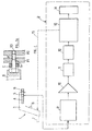
- FIG. 1A of the accompanying drawings shows in sectional view the test assembly used by the Applicant in these investigations.
- This test assembly had two pieces P1 and P2 to be clamped against each other with a screw V.
- the piece P1 was a relatively non-rigid plastic plate and the piece P2 was a metal sheet.
- the screw passed through a smooth hole T1 of the workpiece P1 and was screwed into a threaded hole T2 of the other workpiece.
- a stress sensor C which measured the stress exerted by the head of the screw V on the face of the part P1 during the various phases of the clamping operation using a hammer screwdriver.
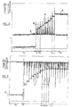
- the pace of the The stress as a function of the time recorded by this sensor C is shown by the curves A of FIGS. 2 and 3.
- FIG. 2 shows these curves for a hammer screwing machine with automatic cut-off of its pneumatic supply, this cut occurring when the value of the tightening torque chosen by the operator is reached during a clamping operation and FIG. analogous, but for a pounding screwdriver without automatic shut off pneumatic supply.
- the test illustrated in Figure 2 shows approximately steady growth of the peaks representing the tightening torque applied at the beginning of each pounding cycle. However, it turns out that such a regular growth is not, and by far, the general case, the highest peak peaks can occur while the desired nominal stress in the assembly is not yet reached .
- the diagram shown in FIG. 3 shows the stress and torque curves of such a case.
- the beginning of the tightening also corresponds to a constant overall rate (curve A) of the stress while the pieces P1 and P2 are brought in support on one another. Then, during the pounding cycles t 1 to t n-1 , the stress increases steadily in the assembly until reaching a constant value which reflects the completion of the tightening of the assembly.
- the peaks of the curve 3 representative of the pair of tightening applied at each stroke of the screwdriver vary considerably and irregularly from one cycle to the next cycle, so that from the peak information provided by the torque sensor, it is impossible to deduce, if the assembly has been tight at the fair value of stress or not.
- This phenomenon of irregularity of the torque applied to the screw V comes from several factors which are difficult to control and vary considerably, particularly as a function of the surface condition of the parts of the assembly (presence of grease or dirt on the parts), the number of superimposed components of the assembly, more or less compressible materials of parts etc. It should be noted that the irregularities of the peaks can occur both for a screwdriver with automatic power failure and for a screwdriver without this cut.
- a strain sensor such as the sensor C of FIG. 1A can obviously not be installed in practice in an assembly (it could no longer be removed) so that in fact the information concerning the stress is not available for proper control of the tightening process.
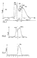
- FIG. 4 represents, on a time scale of significantly greater resolution, the shape of one of the peaks of the diagrams of FIGS. 2 and 3, such a peak corresponding to a shot of the screwdriver, it being understood that all the peaks generally have a roughly similar profile.
- each peak is preceded by a stopping time (phase P1) of the screwdriver during which the torque is substantially zero, followed by a phase P2 of sudden rise towards an absolute maximum M1 (which is in fact the only one). maximum value visible at each peak in Figures 2 and 3).
- phase P3 shows that the screwdriver has overcome the resistance opposing the rotation of the screw V, the supplied torque then evolving towards a relative minimum value M2, to immediately go back to a relative maximum M3, the transition corresponding to a rotation of the screw against the friction forces generated on its threads and those of the hole T2.
- this clamping is done in two steps (relative minimum M4 and relative maximum M5) but this is not systematic for all cases.
- Phase P4 begins with the sudden release of the force provided by the screwdriver (the step is completed) so that the applied torque decreases to zero.
- a new pounding cycle begins with the creation of a torque profile that may have the same overall shape as the previous cycle, but with different maximum and minimum values, precisely because of all the factors. of uncertainty listed above.
- a following cycle of a tightening process may have a shape such as that shown in FIG. 5 in which the directions of the variations of the tightening torque are approximately similar, while the values of the cusp points of the curve are all different.
- the torque M1a necessary to "take off” the screw by applying a twist to it is here a relative maximum, less than the maximum absolute torque M4a that will increase the stress installed in the assembly during this pounding cycle.
- the present invention proposes to exploit this knowledge concerning the assembly process carried out with the aid of a hydro-pneumatic hammering screwdriver and it is therefore intended to provide a method for measuring the torque installed using a sensor interposed between the screwdriver and the assembly is to control a hydropneumatic hammer screwdriver to stop the screwing at the moment when the desired nominal stress is installed in a screw connection.
- the invention also aims to provide equipment for implementing this measurement and / or control method.
- the screwing process can be stopped when it is certain that the assembly is completely tightened and that no backlash of play or elastic deformation in the assembly is still possible.
- the tightening operation will therefore practically lead to to install in the assembly the maximum stress value that can be obtained without this stress value being available or being measured.
- the method of the invention also consists in detecting in each of said cycles preceding said cycle having only one maximum of said measurement signal, at least one other maximum, to memorize the value of this other maximum during the next cycle of this signal and displaying said value if, during the current cycle of said signal, only one maximum is detected.
- an operator can easily cause the stopping of the screwdriver by observing the display by manual cut-off of the power supply thereof.
- the stopping of said screwdriver is caused automatically by cutting off its power supply, by means of a generated stop signal, following the detection of a single maximum during the current cycle of said measurement signal.
- the invention also relates to a screwing equipment controlled by the method as defined above, this equipment comprising a hydro-pneumatic hammer driver having a drive shaft which, by means of a screwdriver bit, can apply a tightening torque to screw means by which an assembly is to be tightened, the screwdriver also comprising a screwdriver torque which is associated with said drive shaft and which delivers a measurement signal representing the instantaneous torque transmitted by said tip on said screwing means, this measurement signal comprising a succession of cycles respectively representative of the evolution of the tightening torque during the successive strokes applied by the screwdriver on said screwing means, and control means for stopping the screwdriver, characterized in that said control means also comprises means for analyzing each of the cycles of said measurement signal, said analysis means being arranged to supply the value of the torque applied to the assembly, as soon as a cycle of said signal measurement has only one maximum.
- FIG. 1 very schematically represents a hammer driver 1 equipped with an electronic apparatus 2, the assembly being designed for implementing the method according to the invention.
- the screwdriver 1 essentially comprises a body 3 having an anatomical shape so that it can easily be manipulated by hand.
- This body 3 encloses the mechanical members known per se of the screwdriver, among which only drive shaft 4 is shown, a torque sensor 5 and a coupling end 6 intended to cap the head of a screwdriver. screw, a nut, or other similar screwable member, when tightening an assembly.
- Screwdrivers of this type are marketed for example by ATLAS COPCO S-10523, Sweden or by DGD GmbH, Postfach 30, D 73461 WESTHAUSEN / Würth, Germany.
- the sensor 5 can be made using strain gauges placed on the drive shaft 4 of the screwdriver and appropriately connected to provide an electrical voltage across the sensor representative of the torque applied to the tip. 6.
- the terminals of the sensor 5 are connected to the electronic equipment 2 which comprises an analog filter 9 to clear the signal from the sensor, an amplifier 10 connected to the filter 9 followed by an analog / digital converter 11, a filter 12 of a processing module 13 and a display 14.
- the processing module 13 comprises a microprocessor (not shown) capable of executing a program whose essential steps are illustrated in FIG. 7 and which will be described by FIG. the following.
- the processing module 13 may possibly generate a signal for cutting off the pneumatic supply of the screwdriver 1, this signal then being able to transit on a line 15.
- FIG. 7 represents a flowchart that can be executed in the processing module 13 of FIG. 1 for carrying out the method according to the invention.
- This flow chart takes place during each tightening process.
- the operation E2 consists in searching for a first maximum value M1 (FIG. 4) of the torque value from the signal coming from the sensor 5, this signal being shaped, amplified and digitized in the filtering, amplifying stages. and conversion 9 to 12 of Figure 1.
- the operation E3 consists in detecting in the signal whether the maximum value M1 is followed by a relative minimum M2 corresponding to a trough of the torque profile. A test is then performed in step E4 to determine if the relative minimum point M2 is followed by a relative maximum point (search for the point M3) corresponding to a second peak of the torque profile.
- the program proceeds to an evaluation step E5 of the value of the tightening torque which is the one corresponding to the maximum observed. This value is then displayed during a step E6 on the dial of the screwdriver. The operator stops the tightening process.
- step E4 notes the presence of a second peak
- a test is performed during the step E7 to see if a new tightening cycle has begun. If it is not the case, it is because the screwdriver has been stopped by the operator and in this case the value of the second or the third peak memorized during the previous cycle is calculated in E8 and the corresponding value is displayed by step E6.
- step E7 If, on the contrary, during the test of step E7, it turns out that a new pounding cycle has begun, the search is again made for an absolute maximum in E9 followed by the search for a new minimum. relative to E10, these steps being similar to steps E2 and E3.
- step E10 a test is performed at E11 to see if the first peak is followed by a second peak. If the response is negative, the value of the second or third peak of the torque profile of the preceding cycle is calculated at E12, which then corresponds to the nominal value of the torque applied to the assembly. This value stored during the previous cycle is displayed by step E6 during the current cycle and the operator can stop the screwdriver.
- the program waits for the next pounding cycle by testing step E13. If there is a cycle following the loop is again traversed by the steps E9, E10 and E11.
- step E13 If, on the other hand, the test of step E13 proves to be negative, it is because the assembly is tight and the value of the second or third peak of the torque profile of the previous cycle is displayed during step E12.
- the display step E6 can be performed at the same time as a step E14 of controlling the automatic cutting of the screwdriver via the order 15. It should be noted that this automatic cut-off will be carried out according to the actual tightening torque applied to the assembly to install the required tension.
Landscapes
- Engineering & Computer Science (AREA)
- Mechanical Engineering (AREA)
- Details Of Spanners, Wrenches, And Screw Drivers And Accessories (AREA)
Claims (6)
- Verfahren zur Messung und/oder zur Steuerung eines Schraubgeräts, aufweisend:- einen hydropneumatischen Impulsschrauber (1), welcher eine Antriebswelle (4) aufweist, welche über einen Schraubansatz (6) ein Spannmoment an Schraubmittel (V, T2) anlegen kann, über welche eine Verbindung gespannt werden muss, wobei der Schrauber ebenso einen Momentensensor (5) aufweist, welcher der Antriebswelle (4) hinzugefügt ist, und welcher ein Messsignal liefert, das stellvertretend für das durch den Ansatz (6) auf die Schraubmittel (V, T2) momentan übertragene Moment ist, wobei dieses Messsignal eine Aufeinanderfolge von Zyklen umfasst, die jeweils stellvertretend sind für die Entwicklung des Spannmoments während der aufeinander folgenden Schläge, welche durch den Schrauber (1) auf die Schraubmittel erfolgen, und- Steuermittel (8) zum Anhalten des Schraubers (1);
wobei dieses Verfahren dadurch gekennzeichnet, dass es besteht aus:- dem Erfassen von mindestens einem Maximum (M1, M3, M5) in jedem der Zyklen des Signals; und- dem Anhalten des Schraubers (1) sobald ein Zyklus nur ein einziges Maximum (Mn) aufweist. - Verfahren nach Anspruch 1, dadurch gekennzeichnet, dass es besteht aus:- dem Erfassen in jedem der Zyklen vorangehend zu dem Zyklus, welcher nur ein einziges Maximum aufweist, des Messsignals mindestens eines anderen Maximums (M3, M5);- dem Speichern des Wertes dieses anderen Maximums im Verlaufe des nachfolgenden Zyklus dieses Signals und;- dem Anzeigen des Wertes, wenn während dem laufenden Zyklus des Signals ein einziges Maximum (Mn) erfasst wird.
- Verfahren nach irgendeinem der Ansprüche 1 und 2, dadurch gekennzeichnet, dass das Anhalten des Schraubers (1) automatisch durch Abschaltung seiner Versorgung (7) hervorgerufen wird mittels eines Stoppsignals (15), das folgend auf die Erfassung eines einzigen Maximums (Mn) während des laufenden Zyklus des Messsignals erzeugt wird.
- Schraubgerät, welches durch das Verfahren gemäß einem der Ansprüche 1 bis 3 gesteuert wird, aufweisend einen hydropneumatischen Impulsschrauber (1), welcher eine Antriebswelle (4) aufweist, welche über einen Schraubansatz (6) ein Spannmoment an Schraubmittel (V, T2) anlegen kann, über welche eine Verbindung gespannt werden muss, wobei der Schrauber (1) ebenso einen Momentensensor (5) aufweist, welcher der Antriebswelle (4) hinzugefügt ist, und welcher ein Messsignal liefert, das stellvertretend ist für das momentane Moment, welches durch den Ansatz (6) an die Schraubmittel (V, T2) übertragen wird, wobei dieses Messsignal eine Aufeinanderfolge von Zyklen aufweist, die jeweils stellvertretend sind für die Entwicklung des Spannmoments während den aufeinander folgenden Schlägen, welche durch den Schrauber auf die Spannmittel erfolgen, und Steuermittel (8) zum Anhalten des Schraubers (1),
dadurch gekennzeichnet, dass die Steuermittel ebenso Analysemittel (9 bis 13) jedes der Zyklen des Messsignals aufweisen, wobei die Analysemittel angeordnet sind, um den Wert des an der Verbindung angelegten Moments zu liefern, sobald ein Zyklus des Messsignals nur ein einziges Maximum (Mn) aufweist. - Gerät nach Anspruch 4 für die Umsetzung des Verfahrens nach Anspruch 2, dadurch gekennzeichnet, dass die Steuermittel manuelle Abschaltungsmittel (8) der Versorgung und Mittel (14) zum Anzeigen des Wertes aufweisen.
- Gerät nach Anspruch 4 für die Umsetzung des Verfahrens nach Anspruch 3, dadurch gekennzeichnet, dass die Steuermittel Mittel (15) aufweisen, welche mit den Analysemitteln verbunden sind und fähig sind, das automatische Anhalten des Schraubers (1) hervorzurufen.
Applications Claiming Priority (2)
| Application Number | Priority Date | Filing Date | Title |
|---|---|---|---|
| FR9814353A FR2785986B1 (fr) | 1998-11-16 | 1998-11-16 | Procede de mesure et/ou de commande d'un equipement de vissage comprenant une visseuse hydropneumatique a martelement |
| FR9814353 | 1998-11-16 |
Publications (2)
| Publication Number | Publication Date |
|---|---|
| EP1000710A1 EP1000710A1 (de) | 2000-05-17 |
| EP1000710B1 true EP1000710B1 (de) | 2006-01-18 |
Family
ID=9532763
Family Applications (1)
| Application Number | Title | Priority Date | Filing Date |
|---|---|---|---|
| EP19990402779 Expired - Lifetime EP1000710B1 (de) | 1998-11-16 | 1999-11-08 | Verfahren zum Messen und/oder Ansteuern bei einer Schraubvorrichtung mit einem hydropneumatischen Impulsschrauber |
Country Status (3)
| Country | Link |
|---|---|
| EP (1) | EP1000710B1 (de) |
| DE (1) | DE69929510T2 (de) |
| FR (1) | FR2785986B1 (de) |
Families Citing this family (2)
| Publication number | Priority date | Publication date | Assignee | Title |
|---|---|---|---|---|
| JP6646858B2 (ja) * | 2016-11-30 | 2020-02-14 | パナソニックIpマネジメント株式会社 | インパクト回転工具 |
| FR3144031B1 (fr) * | 2022-12-26 | 2024-11-22 | Renault Georges Ets | Dispositif de vissage à gain et/ou fréquence de coupure variable en fonction du couple de serrage objectif |
Family Cites Families (4)
| Publication number | Priority date | Publication date | Assignee | Title |
|---|---|---|---|---|
| DE4243069C2 (de) * | 1992-12-18 | 2001-09-27 | Gardner Denver Gmbh | Impulswerkzeug, insbesondere Impulsschrauber |
| DE4429282A1 (de) * | 1994-08-18 | 1996-02-22 | Cooper Ind Inc | Hydro-Impulsschrauber insbesondere zum Anziehen von Schraubverbindungen |
| DE19503524A1 (de) * | 1995-02-03 | 1996-08-08 | Bosch Gmbh Robert | Impulsschrauber und Verfahren zum Anziehen einer Schraubverbindung mittels des Impulsschraubers |
| SE511336C2 (sv) * | 1997-10-27 | 1999-09-13 | Atlas Copco Tools Ab | Metod för fastställande av det installerade momentet i ett skruvförband vid impulsåtdragning, metod för styrning av en åtdragningsprocess, metod för kvalitetsövervakning och ett momentimpulsverktyg för åtdragning av skruvförband |
-
1998
- 1998-11-16 FR FR9814353A patent/FR2785986B1/fr not_active Expired - Fee Related
-
1999
- 1999-11-08 EP EP19990402779 patent/EP1000710B1/de not_active Expired - Lifetime
- 1999-11-08 DE DE69929510T patent/DE69929510T2/de not_active Expired - Lifetime
Also Published As
| Publication number | Publication date |
|---|---|
| DE69929510T2 (de) | 2006-07-20 |
| FR2785986A1 (fr) | 2000-05-19 |
| FR2785986B1 (fr) | 2000-12-29 |
| EP1000710A1 (de) | 2000-05-17 |
| DE69929510D1 (de) | 2006-04-06 |
Similar Documents
| Publication | Publication Date | Title |
|---|---|---|
| EP1751513B1 (de) | Verfahren zur kontrolle der zugspannung eines bolzenschaftes wie etwa einer schraube oder eines spannstiftes sowie verfahren zur durchführung dieses verfahrens | |
| EP2057450B1 (de) | Verfahren und vorrichtung zur einrichtung und steuerung der hydraulischen aufspannung einer oder mehrerer schrauben | |
| EP0674566B1 (de) | Verfahren zur kontrolle und steuerung von der spannung in gewindebolzen | |
| JPH11254340A (ja) | ねじ継手の取付けトルクの測定方法、締付け制御方法、締付けの品質検査方法及びねじ継手締付け用のトルク衝撃供給動力工具 | |
| FR2699446A1 (fr) | Procédé et dispositif pour serrer ou desserrer, avec contrôle de l'angle de rotation, des systèmes de vissage. | |
| FR2751077A1 (fr) | Procede et dispositif pour tester des tournevis | |
| EP0221802A1 (de) | Sicherheitswerkzeughalter für Werkzeugmaschine | |
| FR2852879A1 (fr) | Cle a serrage controle | |
| EP3202980B1 (de) | Verfahren zur einstellung einer maschine zum festziehen von mit bolzen befestigten halterungen von schienen eines bahngleises, insbesondere mit stockschrauben oder muttern, system zur umsetzung dieses verfahrens und mit einem solchen system ausgestattete maschine | |
| EP1000710B1 (de) | Verfahren zum Messen und/oder Ansteuern bei einer Schraubvorrichtung mit einem hydropneumatischen Impulsschrauber | |
| WO2017118960A1 (fr) | Système de serrage et de desserrage d'éléments de fixation et procédés de serrage et de desserrage associés | |
| US10850375B2 (en) | Clamp force estimation via pulsed tightening | |
| WO2012120221A1 (fr) | Methode et dispositif de serrage d'un ensemble visse | |
| FR2510456A1 (fr) | Appareil simplifie de fixation d'un assemblage a vis, selon un procede de taux logarithmique | |
| JP6528232B2 (ja) | 電動回転工具のねじ締め状態検出装置及びそのトルク調整方法並びにその使用によるねじ締め制御方法 | |
| FR3106634A1 (fr) | Ecrou comprenant au moins une jauge de déformation, boulon comportant au moins un tel écrou et dispositif de mesure d’une précharge exercée par un tel boulon | |
| JP4341350B2 (ja) | ねじ締付け方法 | |
| EP1456555A1 (de) | Elektromechanische bremsanlage und verfahren zu deren steuerung | |
| US20090173194A1 (en) | Impact wrench structure | |
| EP1592534B1 (de) | Vorrichtung zum schleifen von ophthalmischen linsen mit verbessertem mittel zum festklemmen des glasrohlings zum schleifen | |
| WO2025082860A1 (fr) | Dispositif de vissage/dévissage à détorsion optimisée | |
| EP4467290A1 (de) | Verfahren zur servoinstallation einer gewindebefestigung | |
| FR2860176A3 (fr) | Dispositif de controle pour cle dynamometrique | |
| EP3781356B1 (de) | Elektrisches impulshandwerkzeug und verfahren zum spannen | |
| EP0119926A1 (de) | Verfahren und Einrichtung zum Anziehen von Schrauben oder dergl. bis zur Elastizitätsgrenze |
Legal Events
| Date | Code | Title | Description |
|---|---|---|---|
| PUAI | Public reference made under article 153(3) epc to a published international application that has entered the european phase |
Free format text: ORIGINAL CODE: 0009012 |
|
| AK | Designated contracting states |
Kind code of ref document: A1 Designated state(s): DE GB IT |
|
| AX | Request for extension of the european patent |
Free format text: AL;LT;LV;MK;RO;SI |
|
| 17P | Request for examination filed |
Effective date: 20001117 |
|
| AKX | Designation fees paid |
Free format text: DE GB IT |
|
| RAP1 | Party data changed (applicant data changed or rights of an application transferred) |
Owner name: RENAULT S.A.S. |
|
| 17Q | First examination report despatched |
Effective date: 20031208 |
|
| GRAP | Despatch of communication of intention to grant a patent |
Free format text: ORIGINAL CODE: EPIDOSNIGR1 |
|
| GRAS | Grant fee paid |
Free format text: ORIGINAL CODE: EPIDOSNIGR3 |
|
| GRAA | (expected) grant |
Free format text: ORIGINAL CODE: 0009210 |
|
| AK | Designated contracting states |
Kind code of ref document: B1 Designated state(s): DE GB IT |
|
| PG25 | Lapsed in a contracting state [announced via postgrant information from national office to epo] |
Ref country code: IT Free format text: LAPSE BECAUSE OF FAILURE TO SUBMIT A TRANSLATION OF THE DESCRIPTION OR TO PAY THE FEE WITHIN THE PRESCRIBED TIME-LIMIT;WARNING: LAPSES OF ITALIAN PATENTS WITH EFFECTIVE DATE BEFORE 2007 MAY HAVE OCCURRED AT ANY TIME BEFORE 2007. THE CORRECT EFFECTIVE DATE MAY BE DIFFERENT FROM THE ONE RECORDED. Effective date: 20060118 |
|
| REG | Reference to a national code |
Ref country code: GB Ref legal event code: FG4D Free format text: NOT ENGLISH |
|
| GBT | Gb: translation of ep patent filed (gb section 77(6)(a)/1977) |
Effective date: 20060223 |
|
| REF | Corresponds to: |
Ref document number: 69929510 Country of ref document: DE Date of ref document: 20060406 Kind code of ref document: P |
|
| PLBE | No opposition filed within time limit |
Free format text: ORIGINAL CODE: 0009261 |
|
| STAA | Information on the status of an ep patent application or granted ep patent |
Free format text: STATUS: NO OPPOSITION FILED WITHIN TIME LIMIT |
|
| 26N | No opposition filed |
Effective date: 20061019 |
|
| PGFP | Annual fee paid to national office [announced via postgrant information from national office to epo] |
Ref country code: DE Payment date: 20141119 Year of fee payment: 16 Ref country code: GB Payment date: 20141119 Year of fee payment: 16 |
|
| REG | Reference to a national code |
Ref country code: DE Ref legal event code: R119 Ref document number: 69929510 Country of ref document: DE |
|
| GBPC | Gb: european patent ceased through non-payment of renewal fee |
Effective date: 20151108 |
|
| PG25 | Lapsed in a contracting state [announced via postgrant information from national office to epo] |
Ref country code: GB Free format text: LAPSE BECAUSE OF NON-PAYMENT OF DUE FEES Effective date: 20151108 Ref country code: DE Free format text: LAPSE BECAUSE OF NON-PAYMENT OF DUE FEES Effective date: 20160601 |