EP1000836A2 - Direction assistée - Google Patents
Direction assistée Download PDFInfo
- Publication number
- EP1000836A2 EP1000836A2 EP99122347A EP99122347A EP1000836A2 EP 1000836 A2 EP1000836 A2 EP 1000836A2 EP 99122347 A EP99122347 A EP 99122347A EP 99122347 A EP99122347 A EP 99122347A EP 1000836 A2 EP1000836 A2 EP 1000836A2
- Authority
- EP
- European Patent Office
- Prior art keywords
- acceleration
- vehicle
- rotation speed
- steering
- electric motor
- Prior art date
- Legal status (The legal status is an assumption and is not a legal conclusion. Google has not performed a legal analysis and makes no representation as to the accuracy of the status listed.)
- Granted
Links
Images

Classifications
-
- B—PERFORMING OPERATIONS; TRANSPORTING
- B62—LAND VEHICLES FOR TRAVELLING OTHERWISE THAN ON RAILS
- B62D—MOTOR VEHICLES; TRAILERS
- B62D5/00—Power-assisted or power-driven steering
- B62D5/06—Power-assisted or power-driven steering fluid, i.e. using a pressurised fluid for most or all the force required for steering a vehicle
- B62D5/065—Power-assisted or power-driven steering fluid, i.e. using a pressurised fluid for most or all the force required for steering a vehicle characterised by specially adapted means for varying pressurised fluid supply based on need, e.g. on-demand, variable assist
-
- B—PERFORMING OPERATIONS; TRANSPORTING
- B62—LAND VEHICLES FOR TRAVELLING OTHERWISE THAN ON RAILS
- B62D—MOTOR VEHICLES; TRAILERS
- B62D6/00—Arrangements for automatically controlling steering depending on driving conditions sensed and responded to, e.g. control circuits
- B62D6/02—Arrangements for automatically controlling steering depending on driving conditions sensed and responded to, e.g. control circuits responsive only to vehicle speed
Definitions
- the present invention relates to a power steering apparatus and, more particularly, to a so-called motor-driven hydraulic power steering apparatus which is adapted to generate a hydraulic pressure by driving an oil pump by an electric motor to assist a steering operation by the generated hydraulic pressure.
- Motor-driven hydraulic power steering apparatuses are conventionally known which are adapted to rotate an oil pump by an electric motor and supply a working oil to a power cylinder from the oil pump to mitigate an operation force required for operating a steering wheel.
- a steering assist force is determined by the rotation speed of the electric motor. More specifically, a higher rotation speed of the electric motor increases the flow rate of the oil to increase the assist force, while a lower rotation speed of the electric motor reduces the flow rate of the oil to reduce the assist force.
- the assist force is not required when the steering operation is not performed and, therefore, the rotation of the electric motor is stopped or kept in an idling state with an extremely low rotation speed for power saving.
- a power steering apparatus which comprises: acceleration detection means for sensing a fore-and-aft acceleration of a motor vehicle which is expressed as a value prefixed with a sign; and control means for reducing a rotation speed of an electric motor to reduce an assist force in accordance with the acceleration if the value of the acceleration of the vehicle sensed by the acceleration detection means is positive, and increasing the rotation speed of the electric motor to increase the assist force in accordance with the acceleration if the value of the acceleration of the vehicle sensed by the acceleration detection means is negative (claim 1).
- the power steering apparatus allows a driver to constantly obtain a consistent steering feeling irrespective of the fore-and-aft acceleration.
- a power steering apparatus which comprises: acceleration detection means for sensing a fore-and-aft acceleration of a motor vehicle which is expressed as a value prefixed with a sign; and control means for preliminarily setting a rotation speed of an electric motor at a rotation speed level sufficient for generation of an assist force in accordance with the acceleration if the value of the acceleration of the vehicle sensed by the acceleration detection means is not greater than a predetermined negative level when a steering operation is not performed (claim 2).
- the next occurrence of the steering operation can be predicted by detecting an acceleration level not greater than the predetermined negative level and, therefore, the assist force can smoothly be generated immediately after the steering operation is started.
- the aforesaid "predetermined negative level” is defined as a fore-and-aft acceleration level of the vehicle typically sensed when the driver consciously decelerates the vehicle before performing the steering operation.
- the aforesaid "rotation speed level sufficient for generation of an assist force” is defined as a rotation speed level required for generation of a force sufficient to assist the steering operation performed by the driver.
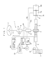
- Fig. 1 is a schematic diagram illustrating the overall construction of a power steering apparatus according to one embodiment of the present invention.
- the power steering apparatus is incorporated in a motor vehicle and adapted to assist a steering operation of a steering mechanism 1.
- the steering mechanism 1 includes a steering wheel 2.
- a steering shaft 3 is coupled to the steering wheel 2, and a pinion gear 4 is attached to the distal end of the steering shaft 3.
- the pinion gear 4 is meshed with a rack gear 5 which extends transversely of the vehicle.
- Front tires 7 are attached to the rack gear 5 via tie rods 6.
- the power steering apparatus further includes a power cylinder 20 for generating a steering assist force.
- the power cylinder 20 includes a piston 21 coupled to the rack shaft 5, and a pair of cylinder chambers 20a, 20b split by the piston 21.
- a hydraulic pressure control valve 23 is connected to the cylinder chambers 20a, 20b via oil supply lines 22a, 22b indicated by broken lines.
- the hydraulic pressure control valve 23 is interposed in an oil circulation line 24 indicated by a broken line. Through the oil circulation line 24, a working oil contained in a reservoir tank 25 is pumped up by an oil pump 26, then discharged from the oil pump 26, and returned into the reservoir tank 25.
- the oil pump 26 is driven and controlled by an electric motor M.
- the oil pump 26 is driven by the electric motor M, the working oil is circulated through the oil circulation line 24. With the oil pump being off, the circulation of the working oil is suspended.
- a torque sensor 27 is provided in association with a torsion bar 8 attached to the steering shaft 3, and outputs a torque signal having a value proportional to the magnitude of a torque applied to the steering shaft 3 and a sign corresponding to the direction of the torque.
- a torque sensor of any type such as a potentiometer having a mechanical contact or a non-contact torque sensor may be employed as the torque sensor 27.
- the hydraulic pressure control valve 23 is adapted to change its valve aperture in accordance with the direction and magnitude of the torque applied to the steering shaft 3, which are sensed by the torque sensor 27.
- the supply of the working oil to the power cylinder 20 can be varied.
- a vehicle speed sensor 28 is provided for sensing the rotation speed of a rotor of a wheel.
- the vehicle speed sensor is a magnetic sensor which is adapted to detect a magnetic metal piece fixed to the rotor or an optical sensor which is adapted to optically detect a hole provided in the rotor.
- the vehicle speed sensor is not necessarily adapted to sense the rotation speed of the rotor, but may be any mechanism which is adapted to sense the speed or acceleration of the motor vehicle.
- the vehicle speed sensor may be adapted to sense the rotation speed of a rotary shaft of a power transmission apparatus of the vehicle. If the vehicle includes such a mechanism that a vehicle speed signal can be obtained for an ABS control or the like, the mechanism may be used as the vehicle speed sensor.
- the electric motor M is driven by a driving circuit 29.
- the driving circuit 29 is controlled by an electronic control unit ECU.
- the electronic control unit ECU includes a microprocessor having a CPU, a ROM and a RAM.
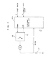
- Fig. 2 is a diagram illustrating electrical interconnection of the electronic control unit ECU and the like.
- a torque signal T and a vehicle speed signal V are applied to the electronic control unit ECU from the torque sensor 27 and the vehicle speed sensor 28, respectively.
- a power is supplied to the electric motor M from a battery 30 of the vehicle via the driving circuit 29.
- the driving circuit 29 generates a driving signal pulse-width-modulated at a duty ratio instructed by the electronic control unit ECU.
- a motor electric current flowing through the driving circuit 29 is sensed and inputted to the electronic control unit ECU.
- the electronic control unit ECU controls the driving circuit 29 on the basis of the torque signal applied from the torque sensor 27 and an acceleration signal which is obtained by differentiating the vehicle speed signal V applied from the vehicle speed sensor 28.
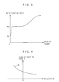
- Fig. 3 is a graph showing a control operation to be performed by the electronic control unit ECU for controlling the rotation speed of the electric motor with respect to a change in the steering operation.
- the rotation speed of the electric motor is set at a stand-by rotation speed Ri when the steering operation is not performed, and increased to an assist rotation speed Rs when the steering operation is started.
- an assist force is generated to assist the steering operation performed by a driver.
- the electronic control unit ECU varies the stand-by rotation speed Ri as shown in Fig. 4. More specifically, the stand-by rotation speed Ri is reduced if the acceleration is applied in a positive direction, and increased if the acceleration is applied in a negative direction.
- the electronic control unit ECU is adapted to vary the stand-by rotation speed Ri stepwise on the basis of a preliminarily stored table indicative of a relationship between the stand-by rotation speed Ri and the acceleration.
- the acceleration of the vehicle is detected, and the stand-by rotation speed Ri is reduced if the acceleration is applied in the positive direction, and increased if the acceleration is applied in the negative direction.
- variations in the steering feeling with a change in the loads on the front wheels can be corrected, so that the power steering apparatus ensures an excellent steering performance.
- the assist rotation speed Rs may also be varied in accordance with the acceleration of the vehicle in the same manner as shown in Fig. 4.
- the electronic control unit ECU varies the motor rotation speed as shown in Fig. 5 when a predetermined negative acceleration is detected in the non-steering state. More specifically, if the acceleration is not greater than a predetermined negative level A, the motor rotation speed is increased to the assist rotation speed Rs, whether or not the steering operation is performed.
- the rotation speed of the electric motor is increased by predicting presence of a corner in front, so that a sufficient force can quickly be generated to assist the steering operation.
- control operations shown in Figs. 4 and 5 may be employed either alone or in combination.
- the power steering apparatus can provide such technical effects that the assist force can quickly be generated before the steering operation at deceleration of the vehicle and that the steering does not feel heavier in the steering operation.
- the acceleration of the vehicle is determined by differentiating the vehicle speed signal applied from the vehicle sensor in the aforesaid embodiments, but may be sensed directly by an acceleration sensor.
- a known acceleration sensor such as servo-type acceleration sensor or a piezoelectric-type acceleration sensor is usable as the acceleration sensor.
- the stand-by rotation speed Ri of the electric motor is set at a constant value which is not equal to zero in the embodiment shown in Fig. 5, the present invention is applicable to a case where the stand-by rotation Ri is set at zero or the electric motor is controlled to be stopped in the non-steering state.
- various modifications may be made within the scope of the present invention.
Landscapes
- Engineering & Computer Science (AREA)
- Chemical & Material Sciences (AREA)
- Combustion & Propulsion (AREA)
- Transportation (AREA)
- Mechanical Engineering (AREA)
- Steering Control In Accordance With Driving Conditions (AREA)
- Power Steering Mechanism (AREA)
Applications Claiming Priority (2)
| Application Number | Priority Date | Filing Date | Title |
|---|---|---|---|
| JP31952998 | 1998-11-10 | ||
| JP31952998A JP3688140B2 (ja) | 1998-11-10 | 1998-11-10 | パワーステアリング装置 |
Publications (3)
| Publication Number | Publication Date |
|---|---|
| EP1000836A2 true EP1000836A2 (fr) | 2000-05-17 |
| EP1000836A3 EP1000836A3 (fr) | 2005-02-09 |
| EP1000836B1 EP1000836B1 (fr) | 2009-01-07 |
Family
ID=18111266
Family Applications (1)
| Application Number | Title | Priority Date | Filing Date |
|---|---|---|---|
| EP99122347A Expired - Lifetime EP1000836B1 (fr) | 1998-11-10 | 1999-11-10 | Direction assistée |
Country Status (4)
| Country | Link |
|---|---|
| US (1) | US6305489B1 (fr) |
| EP (1) | EP1000836B1 (fr) |
| JP (1) | JP3688140B2 (fr) |
| DE (1) | DE69940243D1 (fr) |
Cited By (3)
| Publication number | Priority date | Publication date | Assignee | Title |
|---|---|---|---|---|
| GB2346598B (en) * | 1999-02-10 | 2003-02-26 | Bosch Gmbh Robert | Method of reducing the feedback on the steering wheel of a motor vehicle and an active steering system designed for this purpose |
| US7363134B2 (en) | 2004-06-01 | 2008-04-22 | Favess Co. Ltd. | Power steering apparatus |
| CN106741163A (zh) * | 2016-12-27 | 2017-05-31 | 潍柴动力股份有限公司 | 一种车辆转向的控制方法和装置 |
Families Citing this family (6)
| Publication number | Priority date | Publication date | Assignee | Title |
|---|---|---|---|---|
| KR20020043069A (ko) * | 2000-12-01 | 2002-06-08 | 밍 루 | 전동식 파워 스티어링 시스템에 있어서 모터 제어 장치 |
| JP4368742B2 (ja) * | 2004-06-08 | 2009-11-18 | 株式会社日立製作所 | パワーステアリング装置 |
| DE102004028826A1 (de) * | 2004-06-15 | 2006-01-05 | Zf Lenksysteme Gmbh | Servounterstütztes Lenksystem eines Kraftfahrzeugs |
| JP2010215173A (ja) * | 2009-03-18 | 2010-09-30 | Jtekt Corp | パワーステアリング装置 |
| FR2969105B1 (fr) * | 2010-12-21 | 2012-12-21 | Renault Sa | Procede de controle d'un dispositif de direction assistee pour vehicule automobile equipe d'un systeme stop & start. |
| JP5998630B2 (ja) * | 2012-05-17 | 2016-09-28 | いすゞ自動車株式会社 | パワーステアリングシステム、それを搭載した車両、及びその制御方法 |
Family Cites Families (7)
| Publication number | Priority date | Publication date | Assignee | Title |
|---|---|---|---|---|
| EP0239327B1 (fr) * | 1986-03-26 | 1991-07-31 | Mitsubishi Denki Kabushiki Kaisha | Direction assistée entraînée par moteur pour un véhicule |
| EP0514962B1 (fr) * | 1991-05-22 | 1995-07-12 | Delco Electronics Corporation | Opération consistant à faire la moyenne de vitesse pour une direction assistée avec effort variable du conducteur |
| JP3339131B2 (ja) * | 1993-09-30 | 2002-10-28 | 豊田工機株式会社 | 動力舵取装置 |
| US5691900A (en) * | 1994-07-28 | 1997-11-25 | Kelsey-Hayes Company | Method and system for turning detection |
| US5758741A (en) * | 1994-10-31 | 1998-06-02 | Jidosha Kiki Co., Ltd. | Vehicle power steering system |
| US5749431A (en) * | 1996-06-06 | 1998-05-12 | General Motors Corporation | Vehicle power steering system |
| JP3753511B2 (ja) * | 1997-08-27 | 2006-03-08 | 本田技研工業株式会社 | 電動パワーステアリング装置 |
-
1998
- 1998-11-10 JP JP31952998A patent/JP3688140B2/ja not_active Expired - Fee Related
-
1999
- 1999-11-01 US US09/431,186 patent/US6305489B1/en not_active Expired - Lifetime
- 1999-11-10 DE DE69940243T patent/DE69940243D1/de not_active Expired - Lifetime
- 1999-11-10 EP EP99122347A patent/EP1000836B1/fr not_active Expired - Lifetime
Non-Patent Citations (1)
| Title |
|---|
| None |
Cited By (3)
| Publication number | Priority date | Publication date | Assignee | Title |
|---|---|---|---|---|
| GB2346598B (en) * | 1999-02-10 | 2003-02-26 | Bosch Gmbh Robert | Method of reducing the feedback on the steering wheel of a motor vehicle and an active steering system designed for this purpose |
| US7363134B2 (en) | 2004-06-01 | 2008-04-22 | Favess Co. Ltd. | Power steering apparatus |
| CN106741163A (zh) * | 2016-12-27 | 2017-05-31 | 潍柴动力股份有限公司 | 一种车辆转向的控制方法和装置 |
Also Published As
| Publication number | Publication date |
|---|---|
| US6305489B1 (en) | 2001-10-23 |
| EP1000836A3 (fr) | 2005-02-09 |
| JP3688140B2 (ja) | 2005-08-24 |
| JP2000142436A (ja) | 2000-05-23 |
| EP1000836B1 (fr) | 2009-01-07 |
| DE69940243D1 (de) | 2009-02-26 |
Similar Documents
| Publication | Publication Date | Title |
|---|---|---|
| US6216814B1 (en) | Power steering apparatus | |
| EP0190678B1 (fr) | Méthode et système de direction assistée électromotrice | |
| EP0930215B1 (fr) | Systeme de direction assistee | |
| EP0930216B1 (fr) | Systeme de direction assistee | |
| EP0787642A2 (fr) | Procédé et appareil pour la compensation d'effet du couple entraînant sur la direction | |
| US5978721A (en) | Steering control apparatus utilizing a hysteresis control of a steering torque | |
| JPWO1999008921A1 (ja) | パワーステアリング装置 | |
| JPWO1999008922A1 (ja) | パワーステアリング装置 | |
| US8352123B2 (en) | Control device of electric power steering device for vehicles in which steered wheels are driven | |
| US6244372B1 (en) | Power steering apparatus | |
| US6305489B1 (en) | Power steering apparatus | |
| RU2380265C1 (ru) | Устройство рулевого управления транспортным средством | |
| JP3668614B2 (ja) | パワーステアリング装置 | |
| US6250418B1 (en) | Power steering apparatus | |
| EP1016583A1 (fr) | Dispositif de direction assistee | |
| EP0987163B1 (fr) | Direction assistée | |
| US6334502B1 (en) | Power steering apparatus | |
| JPH11255134A (ja) | 電動油圧パワーステアリング装置 | |
| JP3671136B2 (ja) | パワーステアリング装置 | |
| JP2002120741A (ja) | パワーステアリング装置 | |
| EP1900604B1 (fr) | Système de direction assistée | |
| CA2497729C (fr) | Systeme de direction assistee | |
| JPH0637180B2 (ja) | 4輪操舵装置 | |
| JPH01233168A (ja) | 車両用動力操舵装置の制御装置 | |
| JP2002220064A (ja) | パワーステアリング装置 |
Legal Events
| Date | Code | Title | Description |
|---|---|---|---|
| PUAI | Public reference made under article 153(3) epc to a published international application that has entered the european phase |
Free format text: ORIGINAL CODE: 0009012 |
|
| AK | Designated contracting states |
Kind code of ref document: A2 Designated state(s): AT BE CH CY DE DK ES FI FR GB GR IE IT LI LU MC NL PT SE |
|
| AX | Request for extension of the european patent |
Free format text: AL;LT;LV;MK;RO;SI |
|
| PUAL | Search report despatched |
Free format text: ORIGINAL CODE: 0009013 |
|
| AK | Designated contracting states |
Kind code of ref document: A3 Designated state(s): AT BE CH CY DE DK ES FI FR GB GR IE IT LI LU MC NL PT SE |
|
| AX | Request for extension of the european patent |
Extension state: AL LT LV MK RO SI |
|
| 17P | Request for examination filed |
Effective date: 20050324 |
|
| AKX | Designation fees paid |
Designated state(s): DE FR GB |
|
| RAP1 | Party data changed (applicant data changed or rights of an application transferred) |
Owner name: JTEKT CORPORATION |
|
| 17Q | First examination report despatched |
Effective date: 20070104 |
|
| GRAP | Despatch of communication of intention to grant a patent |
Free format text: ORIGINAL CODE: EPIDOSNIGR1 |
|
| RIC1 | Information provided on ipc code assigned before grant |
Ipc: B62D 6/00 20060101ALI20080416BHEP Ipc: B62D 5/065 20060101AFI20080416BHEP |
|
| GRAS | Grant fee paid |
Free format text: ORIGINAL CODE: EPIDOSNIGR3 |
|
| GRAA | (expected) grant |
Free format text: ORIGINAL CODE: 0009210 |
|
| AK | Designated contracting states |
Kind code of ref document: B1 Designated state(s): DE FR GB |
|
| REG | Reference to a national code |
Ref country code: GB Ref legal event code: FG4D |
|
| REF | Corresponds to: |
Ref document number: 69940243 Country of ref document: DE Date of ref document: 20090226 Kind code of ref document: P |
|
| PLBE | No opposition filed within time limit |
Free format text: ORIGINAL CODE: 0009261 |
|
| STAA | Information on the status of an ep patent application or granted ep patent |
Free format text: STATUS: NO OPPOSITION FILED WITHIN TIME LIMIT |
|
| 26N | No opposition filed |
Effective date: 20091008 |
|
| PGFP | Annual fee paid to national office [announced via postgrant information from national office to epo] |
Ref country code: GB Payment date: 20121107 Year of fee payment: 14 |
|
| GBPC | Gb: european patent ceased through non-payment of renewal fee |
Effective date: 20131110 |
|
| PG25 | Lapsed in a contracting state [announced via postgrant information from national office to epo] |
Ref country code: GB Free format text: LAPSE BECAUSE OF NON-PAYMENT OF DUE FEES Effective date: 20131110 |
|
| REG | Reference to a national code |
Ref country code: FR Ref legal event code: PLFP Year of fee payment: 17 |
|
| REG | Reference to a national code |
Ref country code: FR Ref legal event code: PLFP Year of fee payment: 18 |
|
| PGFP | Annual fee paid to national office [announced via postgrant information from national office to epo] |
Ref country code: DE Payment date: 20161101 Year of fee payment: 18 Ref country code: FR Payment date: 20161014 Year of fee payment: 18 |
|
| REG | Reference to a national code |
Ref country code: DE Ref legal event code: R119 Ref document number: 69940243 Country of ref document: DE |
|
| REG | Reference to a national code |
Ref country code: FR Ref legal event code: ST Effective date: 20180731 |
|
| PG25 | Lapsed in a contracting state [announced via postgrant information from national office to epo] |
Ref country code: FR Free format text: LAPSE BECAUSE OF NON-PAYMENT OF DUE FEES Effective date: 20171130 Ref country code: DE Free format text: LAPSE BECAUSE OF NON-PAYMENT OF DUE FEES Effective date: 20180602 |