EP1000874A2 - Récipient sous pression - Google Patents
Récipient sous pression Download PDFInfo
- Publication number
- EP1000874A2 EP1000874A2 EP99810948A EP99810948A EP1000874A2 EP 1000874 A2 EP1000874 A2 EP 1000874A2 EP 99810948 A EP99810948 A EP 99810948A EP 99810948 A EP99810948 A EP 99810948A EP 1000874 A2 EP1000874 A2 EP 1000874A2
- Authority
- EP
- European Patent Office
- Prior art keywords
- valve plate
- insert
- pressure vessel
- ring
- vessel according
- Prior art date
- Legal status (The legal status is an assumption and is not a legal conclusion. Google has not performed a legal analysis and makes no representation as to the accuracy of the status listed.)
- Granted
Links
- 230000001070 adhesive effect Effects 0.000 claims abstract description 9
- 239000004033 plastic Substances 0.000 claims abstract description 8
- 229920003023 plastic Polymers 0.000 claims abstract description 8
- 239000000853 adhesive Substances 0.000 claims abstract description 7
- 229920000098 polyolefin Polymers 0.000 claims abstract description 7
- 238000007789 sealing Methods 0.000 claims description 15
- 239000007788 liquid Substances 0.000 claims description 8
- 239000002184 metal Substances 0.000 claims description 8
- 239000002318 adhesion promoter Substances 0.000 claims description 7
- 229920001296 polysiloxane Polymers 0.000 claims description 7
- 239000000463 material Substances 0.000 claims description 6
- 229920002635 polyurethane Polymers 0.000 claims description 4
- 239000004814 polyurethane Substances 0.000 claims description 4
- 239000013013 elastic material Substances 0.000 claims description 2
- 239000004809 Teflon Substances 0.000 claims 2
- 229920006362 Teflon® Polymers 0.000 claims 2
- 239000012530 fluid Substances 0.000 abstract 1
- 230000007774 longterm Effects 0.000 description 8
- QVGXLLKOCUKJST-UHFFFAOYSA-N atomic oxygen Chemical compound [O] QVGXLLKOCUKJST-UHFFFAOYSA-N 0.000 description 2
- 229910052760 oxygen Inorganic materials 0.000 description 2
- 239000001301 oxygen Substances 0.000 description 2
- 239000004743 Polypropylene Substances 0.000 description 1
- 239000003570 air Substances 0.000 description 1
- 239000012080 ambient air Substances 0.000 description 1
- 238000002788 crimping Methods 0.000 description 1
- 239000003292 glue Substances 0.000 description 1
- 230000037431 insertion Effects 0.000 description 1
- 238000003780 insertion Methods 0.000 description 1
- 239000000203 mixture Substances 0.000 description 1
- -1 polypropylene Polymers 0.000 description 1
- 229920001155 polypropylene Polymers 0.000 description 1
- 230000001737 promoting effect Effects 0.000 description 1
- 239000004447 silicone coating Substances 0.000 description 1
- 239000000126 substance Substances 0.000 description 1
- 230000003746 surface roughness Effects 0.000 description 1
Images


Classifications
-
- B—PERFORMING OPERATIONS; TRANSPORTING
- B65—CONVEYING; PACKING; STORING; HANDLING THIN OR FILAMENTARY MATERIAL
- B65D—CONTAINERS FOR STORAGE OR TRANSPORT OF ARTICLES OR MATERIALS, e.g. BAGS, BARRELS, BOTTLES, BOXES, CANS, CARTONS, CRATES, DRUMS, JARS, TANKS, HOPPERS, FORWARDING CONTAINERS; ACCESSORIES, CLOSURES, OR FITTINGS THEREFOR; PACKAGING ELEMENTS; PACKAGES
- B65D83/00—Containers or packages with special means for dispensing contents
- B65D83/14—Containers for dispensing liquid or semi-liquid contents by internal gaseous pressure, i.e. aerosol containers comprising propellant
- B65D83/38—Details of the container body
-
- B—PERFORMING OPERATIONS; TRANSPORTING
- B65—CONVEYING; PACKING; STORING; HANDLING THIN OR FILAMENTARY MATERIAL
- B65D—CONTAINERS FOR STORAGE OR TRANSPORT OF ARTICLES OR MATERIALS, e.g. BAGS, BARRELS, BOTTLES, BOXES, CANS, CARTONS, CRATES, DRUMS, JARS, TANKS, HOPPERS, FORWARDING CONTAINERS; ACCESSORIES, CLOSURES, OR FITTINGS THEREFOR; PACKAGING ELEMENTS; PACKAGES
- B65D83/00—Containers or packages with special means for dispensing contents
- B65D83/14—Containers for dispensing liquid or semi-liquid contents by internal gaseous pressure, i.e. aerosol containers comprising propellant
- B65D83/68—Dispensing two or more contents
- B65D83/682—Dispensing two or more contents initially separated and subsequently mixed
Definitions
- the invention relates to a pressure vessel according to the preamble of claim 1 or claim 2.
- Such pressure vessels are known and are used in a wide variety of applications, for example for the reception and storage of so-called 2-component products, used.
- Important for pressure vessels to hold such products is that the products can be stored in it for long-term stability.
- the products are also used for a period of several Can be stored in the pressure vessel for months to a few years, without the risk that the pressure is released or that the components react chemically under the influence of air humidity and / or oxygen.
- valve plate together with the Dispensing valves are made from a material that prevents the im Glue the pressure vessel components to the dispensing valves stay and clog them.
- the valve plate is made of one material poor adhesive properties exist, so it is difficult to valve plate to seal long-term, since such a valve plate has so far hardly been used could be glued.
- a reliable, long-term stable sealing is however with generic pressure vessels indispensable.
- Embodiment proposed using the sealing surfaces of the dispensing valves To coat silicone improves the sealing behavior between valve plate and dispensing valves improved, since that is relative Adapt soft silicone to any unevenness in the surface of the valve plate can.
- silicone has a low adhesion, so that in the pressure vessel components do not stick to the dispensing valves.
- Valve plate on its underside a substantially hollow cylindrical Has extension on which a forming a chamber, a hollow cylindrical Containing neck portion container is attached, the extension on the outside is provided with a raised, cylindrical section which has an annular groove in which another O-ring is received which seals the container at the neck portion.
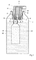
- the pressure vessel has a metal housing 1, which forms a first chamber in its interior, in which a liquid or semi-liquid component K1 is received.
- An insert 2 is inserted into the metal housing 1 from above, on which an overall dispensing device designated 11 is supported.
- This delivery device 11 comprises a valve plate 3, which is fixed to the insert 2.
- a second, inner metal container 10 is fastened, in which a second liquid or semi-liquid component K2 is received.
- an O-ring loaded by a tension ring is provided, or the insert 2 is coated with an adhesion promoter to improve the seal between the valve plate 3 and the insert 2.
- the valve plate 3 is provided with two through bores 6, 7, into each of which a dispensing valve 8, 9 is inserted.
- the dispensing valves 8, 9 are designed to be elastic and in one piece in the longitudinal direction.
- an actuating element 12 is provided, which is provided on the underside with two tubular connecting pieces 14, 15 which extend to the bottom of holes drilled into the dispensing valves 8, 9.
- the valve plate 3 has on its underside an essentially hollow-cylindrical extension 18, to which the inner container 10 is attached.
- the insert 2 is airtightly connected to the metal housing 1 on the top by crimping 19.
- the valve plate 3 consists of a non-adhesive plastic, preferably a polyolefin such as polypropylene, or a halogenated polyolefin. Under non-adhesive plastic "is understood to mean any plastic to which the pressure vessel contents do not stick in visible amounts.
- insert 2 is together with the valve plate 3 and the actuating element 12 is shown in an enlarged view.
- the circularly trained On its underside, insert 2 essentially has a cross section U-shaped edge 20 on the inner, free leg 21 of the edge 20 is embedded in the valve plate 3 such that a cavity 22 between the Valve plate 3 and the insert 2 is created.
- This cavity 22 there is an O-ring 4 used, which is loaded by an annular clamping ring 5.
- the clamping ring 5 is fixed in the insert 2 by a plurality of bulges 24. These bulges 24 are generated by plastic deformation of the insert 2.
- the clamping ring 5 during the attachment of the bulges 24 is preloaded with a certain force, so that the O-ring 4 a takes oval shape and seals on the outside of the valve plate 3 and the inside of the insert 2 and the valve plate 3 against the interior of the pressure vessel seals reliably and with long-term stability.
- the width of the Cavity 22 is preferably slightly larger than the diameter of the O-ring 4 in the unloaded state. As a result, the insertion of the O-ring 4 in the cavity 22 facilitated.
- the extension 18 is on the outside with a raised, cylindrical extending portion 29 provided, the annular groove 30th has, in which a further O-ring 31 is received.
- the inner metal container 10 has a corresponding to the cylindrical section 29, hollow cylindrical neck portion (not shown) to which the O-ring seals creates.
- the extension is with a Provided external thread 32 on which the inner container with a corresponding Internal thread can be screwed.
- Fig. 3 shows an alternative embodiment to that shown in Fig. 2, from one O-ring and a clamping ring 5 existing seal between insert and Valve plate.
- a polyurethane composition is preferably used as the adhesion promoter 13 used, which in addition to good adhesion-promoting properties is permanently elastic.
- the layer thickness of the applied adhesion promoter 13 is preferably about 2 to 20 microns.
- Pressure vessel is universal in terms of the components to be accommodated applicable. It also prevents the pressure in the container from reducing or that the components ingested with oxygen and / or humidity Come into contact. As a result, such containers are particularly suitable for long-term stable storage of the recorded components.
Landscapes
- Chemical & Material Sciences (AREA)
- Dispersion Chemistry (AREA)
- Engineering & Computer Science (AREA)
- Mechanical Engineering (AREA)
- Containers And Packaging Bodies Having A Special Means To Remove Contents (AREA)
- Closures For Containers (AREA)
- Supply Devices, Intensifiers, Converters, And Telemotors (AREA)
Priority Applications (1)
| Application Number | Priority Date | Filing Date | Title |
|---|---|---|---|
| DE29924538U DE29924538U1 (de) | 1998-11-11 | 1999-10-20 | Druckbehälter |
Applications Claiming Priority (2)
| Application Number | Priority Date | Filing Date | Title |
|---|---|---|---|
| DE19851890A DE19851890B4 (de) | 1998-11-11 | 1998-11-11 | Druckbehälter |
| DE19851890 | 1998-11-11 |
Publications (3)
| Publication Number | Publication Date |
|---|---|
| EP1000874A2 true EP1000874A2 (fr) | 2000-05-17 |
| EP1000874A3 EP1000874A3 (fr) | 2000-08-16 |
| EP1000874B1 EP1000874B1 (fr) | 2005-12-07 |
Family
ID=7887351
Family Applications (1)
| Application Number | Title | Priority Date | Filing Date |
|---|---|---|---|
| EP99810948A Expired - Lifetime EP1000874B1 (fr) | 1998-11-11 | 1999-10-20 | Récipient sous pression |
Country Status (3)
| Country | Link |
|---|---|
| EP (1) | EP1000874B1 (fr) |
| AT (1) | ATE312028T1 (fr) |
| DE (2) | DE19851890B4 (fr) |
Cited By (1)
| Publication number | Priority date | Publication date | Assignee | Title |
|---|---|---|---|---|
| EP3312107A4 (fr) * | 2016-01-18 | 2018-09-05 | Toyo Aerosol Industry Co., Ltd. | Base de fixation pour récipient d'aérosol |
Families Citing this family (1)
| Publication number | Priority date | Publication date | Assignee | Title |
|---|---|---|---|---|
| PL2335675T3 (pl) | 2009-12-10 | 2015-08-31 | Neubourg Skin Care Gmbh & Co Kg | Wolne od emulgatorów, stabilizowane polimerem formulacje pianki |
Citations (1)
| Publication number | Priority date | Publication date | Assignee | Title |
|---|---|---|---|---|
| EP0111089A2 (fr) | 1982-11-30 | 1984-06-20 | Ladoco Ag | Récipient sous pression pour gaz, liquides, produits pâteux ou similaires |
Family Cites Families (1)
| Publication number | Priority date | Publication date | Assignee | Title |
|---|---|---|---|---|
| GB2324121A (en) * | 1997-04-07 | 1998-10-14 | Bespak Plc | Seal arrangements for pressurised dispensing containers |
-
1998
- 1998-11-11 DE DE19851890A patent/DE19851890B4/de not_active Expired - Fee Related
-
1999
- 1999-10-20 EP EP99810948A patent/EP1000874B1/fr not_active Expired - Lifetime
- 1999-10-20 AT AT99810948T patent/ATE312028T1/de not_active IP Right Cessation
- 1999-10-20 DE DE59912892T patent/DE59912892D1/de not_active Expired - Lifetime
Patent Citations (1)
| Publication number | Priority date | Publication date | Assignee | Title |
|---|---|---|---|---|
| EP0111089A2 (fr) | 1982-11-30 | 1984-06-20 | Ladoco Ag | Récipient sous pression pour gaz, liquides, produits pâteux ou similaires |
Cited By (2)
| Publication number | Priority date | Publication date | Assignee | Title |
|---|---|---|---|---|
| EP3312107A4 (fr) * | 2016-01-18 | 2018-09-05 | Toyo Aerosol Industry Co., Ltd. | Base de fixation pour récipient d'aérosol |
| US10472163B2 (en) | 2016-01-18 | 2019-11-12 | Toyo Aerosol Industry Co., Ltd. | Fixing plate for aerosol container |
Also Published As
| Publication number | Publication date |
|---|---|
| ATE312028T1 (de) | 2005-12-15 |
| EP1000874B1 (fr) | 2005-12-07 |
| DE59912892D1 (de) | 2006-01-12 |
| EP1000874A3 (fr) | 2000-08-16 |
| DE19851890B4 (de) | 2005-02-10 |
| DE19851890A1 (de) | 2000-05-31 |
Similar Documents
| Publication | Publication Date | Title |
|---|---|---|
| DE102004003439B4 (de) | Farbbechersystem für eine Farbspritzpistole | |
| DE4443287C2 (de) | Ventilanordnung für einen Behälter zur Abgabe von unter Druck stehender Flüssigkeit oder Schaum | |
| EP1718415A1 (fr) | Recipient a ecoulement pour pistolet pulverisateur de peinture | |
| DE4420719C2 (de) | Membranverschlossene Tube mit Nadelverschluß | |
| CH683515A5 (de) | Vorrichtung zum Ausbringen einer aus mindestens zwei Komponenten bestehenden Mischung. | |
| DE10014688A1 (de) | Halteelement zur Befestigung von Bauteilen an einem mit einem Durchbruch versehenen Träger | |
| EP0111089B1 (fr) | Récipient sous pression pour gaz, liquides, produits pâteux ou similaires | |
| EP2389519B1 (fr) | Système de montage | |
| DE19851890B4 (de) | Druckbehälter | |
| DE102015013425A1 (de) | Getränkedose mit einer Verschließ- und Öffnungsvorrichtung | |
| EP4151317A1 (fr) | Tête de distribution et distributeur de liquide doté d'une tête de distribution | |
| DE7505779U (de) | Köcher, insbesondere Verschlußkappe für eine Röhrchenschreiberspitze | |
| DE10231274A1 (de) | Einsatzteil für eine Wandöffnung, insbesondere an einer Fahrzeugkarosserie | |
| DE29924538U1 (de) | Druckbehälter | |
| DE20120142U1 (de) | Sprühdose | |
| EP4124763A1 (fr) | Agencement de fixation | |
| EP0438688A1 (fr) | Vanne d'arrêt | |
| WO1996004483A1 (fr) | Cartouche de colle et dispositif de fixation muni d'une cartouche de colle | |
| DE2901239C2 (de) | Behälter-Verschluß | |
| DE3126508A1 (de) | Dosierventil fuer die abgabe von unter druck stehenden fluessigkeiten | |
| EP0553441A1 (fr) | Appareil pour appliquer un liquide | |
| DE19610184A1 (de) | Ventilaufsatz für Druckdosen | |
| DE20108495U1 (de) | Sprühdose | |
| DE10237864A1 (de) | Verfahren zum Abschliessen eines Drosselklappenstutzens | |
| DE2656492A1 (de) | Einweg-spruehbehaelter fuer fluessige praeparate |
Legal Events
| Date | Code | Title | Description |
|---|---|---|---|
| PUAI | Public reference made under article 153(3) epc to a published international application that has entered the european phase |
Free format text: ORIGINAL CODE: 0009012 |
|
| AK | Designated contracting states |
Kind code of ref document: A2 Designated state(s): AT CH DE FR GB LI |
|
| AX | Request for extension of the european patent |
Free format text: AL;LT;LV;MK;RO;SI |
|
| PUAL | Search report despatched |
Free format text: ORIGINAL CODE: 0009013 |
|
| AK | Designated contracting states |
Kind code of ref document: A3 Designated state(s): AT BE CH CY DE DK ES FI FR GB GR IE IT LI LU MC NL PT SE |
|
| AX | Request for extension of the european patent |
Free format text: AL;LT;LV;MK;RO;SI |
|
| 17P | Request for examination filed |
Effective date: 20001005 |
|
| AKX | Designation fees paid |
Free format text: AT CH DE FR GB LI |
|
| 17Q | First examination report despatched |
Effective date: 20041004 |
|
| GRAP | Despatch of communication of intention to grant a patent |
Free format text: ORIGINAL CODE: EPIDOSNIGR1 |
|
| RIN1 | Information on inventor provided before grant (corrected) |
Inventor name: DR. ING. ROLAND LECHNER |
|
| GRAS | Grant fee paid |
Free format text: ORIGINAL CODE: EPIDOSNIGR3 |
|
| GRAA | (expected) grant |
Free format text: ORIGINAL CODE: 0009210 |
|
| AK | Designated contracting states |
Kind code of ref document: B1 Designated state(s): AT CH DE FR GB LI |
|
| PG25 | Lapsed in a contracting state [announced via postgrant information from national office to epo] |
Ref country code: GB Free format text: LAPSE BECAUSE OF FAILURE TO SUBMIT A TRANSLATION OF THE DESCRIPTION OR TO PAY THE FEE WITHIN THE PRESCRIBED TIME-LIMIT Effective date: 20051207 |
|
| REG | Reference to a national code |
Ref country code: GB Ref legal event code: FG4D Free format text: NOT ENGLISH |
|
| REG | Reference to a national code |
Ref country code: CH Ref legal event code: EP |
|
| REF | Corresponds to: |
Ref document number: 59912892 Country of ref document: DE Date of ref document: 20060112 Kind code of ref document: P |
|
| GBV | Gb: ep patent (uk) treated as always having been void in accordance with gb section 77(7)/1977 [no translation filed] |
Effective date: 20051207 |
|
| PLBE | No opposition filed within time limit |
Free format text: ORIGINAL CODE: 0009261 |
|
| STAA | Information on the status of an ep patent application or granted ep patent |
Free format text: STATUS: NO OPPOSITION FILED WITHIN TIME LIMIT |
|
| PG25 | Lapsed in a contracting state [announced via postgrant information from national office to epo] |
Ref country code: LI Free format text: LAPSE BECAUSE OF NON-PAYMENT OF DUE FEES Effective date: 20061031 Ref country code: CH Free format text: LAPSE BECAUSE OF NON-PAYMENT OF DUE FEES Effective date: 20061031 |
|
| 26N | No opposition filed |
Effective date: 20060908 |
|
| EN | Fr: translation not filed | ||
| REG | Reference to a national code |
Ref country code: CH Ref legal event code: PL |
|
| PG25 | Lapsed in a contracting state [announced via postgrant information from national office to epo] |
Ref country code: FR Free format text: LAPSE BECAUSE OF FAILURE TO SUBMIT A TRANSLATION OF THE DESCRIPTION OR TO PAY THE FEE WITHIN THE PRESCRIBED TIME-LIMIT Effective date: 20070126 |
|
| PG25 | Lapsed in a contracting state [announced via postgrant information from national office to epo] |
Ref country code: AT Free format text: LAPSE BECAUSE OF NON-PAYMENT OF DUE FEES Effective date: 20061020 |
|
| PG25 | Lapsed in a contracting state [announced via postgrant information from national office to epo] |
Ref country code: FR Free format text: LAPSE BECAUSE OF FAILURE TO SUBMIT A TRANSLATION OF THE DESCRIPTION OR TO PAY THE FEE WITHIN THE PRESCRIBED TIME-LIMIT Effective date: 20051207 |
|
| PGFP | Annual fee paid to national office [announced via postgrant information from national office to epo] |
Ref country code: DE Payment date: 20181023 Year of fee payment: 20 |
|
| REG | Reference to a national code |
Ref country code: DE Ref legal event code: R071 Ref document number: 59912892 Country of ref document: DE |