EP1001090A2 - Umstellbare Barriere-Elemente - Google Patents
Umstellbare Barriere-Elemente Download PDFInfo
- Publication number
- EP1001090A2 EP1001090A2 EP99430030A EP99430030A EP1001090A2 EP 1001090 A2 EP1001090 A2 EP 1001090A2 EP 99430030 A EP99430030 A EP 99430030A EP 99430030 A EP99430030 A EP 99430030A EP 1001090 A2 EP1001090 A2 EP 1001090A2
- Authority
- EP
- European Patent Office
- Prior art keywords
- ground
- wall
- separator
- sole
- transverse
- Prior art date
- Legal status (The legal status is an assumption and is not a legal conclusion. Google has not performed a legal analysis and makes no representation as to the accuracy of the status listed.)
- Withdrawn
Links
Images




Classifications
-
- E—FIXED CONSTRUCTIONS
- E01—CONSTRUCTION OF ROADS, RAILWAYS, OR BRIDGES
- E01F—ADDITIONAL WORK, SUCH AS EQUIPPING ROADS OR THE CONSTRUCTION OF PLATFORMS, HELICOPTER LANDING STAGES, SIGNS, SNOW FENCES, OR THE LIKE
- E01F15/00—Safety arrangements for slowing, redirecting or stopping errant vehicles, e.g. guard posts or bollards; Arrangements for reducing damage to roadside structures due to vehicular impact
- E01F15/02—Continuous barriers extending along roads or between traffic lanes
- E01F15/08—Continuous barriers extending along roads or between traffic lanes essentially made of walls or wall-like elements ; Cable-linked blocks
- E01F15/081—Continuous barriers extending along roads or between traffic lanes essentially made of walls or wall-like elements ; Cable-linked blocks characterised by the use of a specific material
- E01F15/085—Continuous barriers extending along roads or between traffic lanes essentially made of walls or wall-like elements ; Cable-linked blocks characterised by the use of a specific material using metal
-
- E—FIXED CONSTRUCTIONS
- E01—CONSTRUCTION OF ROADS, RAILWAYS, OR BRIDGES
- E01F—ADDITIONAL WORK, SUCH AS EQUIPPING ROADS OR THE CONSTRUCTION OF PLATFORMS, HELICOPTER LANDING STAGES, SIGNS, SNOW FENCES, OR THE LIKE
- E01F15/00—Safety arrangements for slowing, redirecting or stopping errant vehicles, e.g. guard posts or bollards; Arrangements for reducing damage to roadside structures due to vehicular impact
- E01F15/02—Continuous barriers extending along roads or between traffic lanes
- E01F15/04—Continuous barriers extending along roads or between traffic lanes essentially made of longitudinal beams or rigid strips supported above ground at spaced points
- E01F15/0476—Foundations
Definitions
- the present invention relates to barrier elements allowing the creation of temporary barriers which are used in particular to separate a taxiway from another taxiway or construction site or land.
- the technical field of the invention is that of manufacturing separating elements (or sections or modules), particularly separating elements essentially made of folded sheet steel, intended for the construction and temporary installation of barriers (or barriers) of mobile or movable safety on the ground.
- Patent EP 485,746 (S.P.S.) describes a barrier element road protection, whose mobility in the event of impact is limited;
- the element is provided with a transverse plate-shaped spacer trapezoidal, which is provided along its entire length with a lower face wavy or zigzag toothed, favoring friction on the ground;
- this structure has drawbacks: the wavy shape of the part toothed prevents it from contributing to the stiffness of the body of the element fence ; moreover, the connection between two elements by a pin engaging in plates, in addition to the drawbacks linked to this organ detachable bonding, also prevents the entire structure of the separator to contribute homogeneously to the impact resistance of a vehicle against a barrier made up of several assembled elements end to end.
- the document EP-A-666376 describes separating elements including each of the lower lateral parts (or longitudinal soles) is inclined to the horizontal.
- the purpose of this request is to propose elements movable barrier dividers, able to be placed or fixed to the ground, of which at least part of the structure is metallic, whose resistance to deformation due to the impact of a vehicle is improved.
- An objective of the invention is to propose cost separators which are improved by providing a higher barrier impact resistant.
- the separator according to the invention is provided, along each of its two lower lateral parts, of a sole (of form longitudinal) integrated into the separator, which is reinforced and preferably inclined (relative to a horizontal plane) by an angle A to less than 10 degrees and less than 30 degrees.
- the value of the angle A is chosen within a range ranging from 13 to 26 degrees, especially ranging from 15 to 24 degrees, and the value of the width L is chosen in a range from 80 to 280 millimeters, in particular from 120 to 220 millimeters.
- the reinforcing means of this sole preferably include a substantially flat part (1m, FIG. 1) (or wall) capable of being placed at flat on the ground, which is rigidly fixed (integrated or welded) at the ends lower elements (1c) of side walls of the separator, i.e. to said first longitudinal edge; this horizontal flat reinforcement wall is extended by a substantially flat part (1n, FIG. 1) (or wall) vertical to form with the horizontal wall (1m) a bent profile in form of ⁇ L ⁇ , i.e. a kind of elongated square extending under the lower end (1c) of the side walls of the separator; fixation longitudinal edges of the sole can be obtained by welding; the square can also be obtained by longitudinal folding of the lower end (1c) of the side blank.
- the reinforced inclined sole extends at least over part the length of the barrier section (or element), preferably at least over 90% of the length (18, FIG. 2) of the section, in particular over the entire length of the section.
- the presence of the flat walls (horizontal (1m) and vertical (1n)) of reinforcement of the sole increases the resistance of the separator, particularly that of the lower edges of the side walls of the separator, in particularly in the preferred case where the sole (or lower structure lateral) forms a triangular profile (1c, 1m, 1n) closed.
- the structure of the separator body is reinforced all the more its two lower lateral parts (soles) are connected by through one (or more) rigid connecting piece (s) which are in particular joined (preferably welded) to each of the Left (G) and Right (D) soles in an internal zone of the sole and preferably substantially along said internal edge (marked 16) of said longitudinal element (1c) of the sole wall.
- This inclined reinforced lower edge allows, when a vehicle presses above by its wheels, not only to resist the resulting deformation of this weight, but also to transmit the weight of the vehicle to separator to reduce the sliding capacity on the floor of the separator, and therefore reduce the deformation of the barrier of which it is a part ; this reinforced side edge also allows when a vehicle presses above by its wheels, to use the entire weight of the vehicle transmitted by the wheels and prevent the lateral overturning of the separator under impact.
- the presence of the reinforcement prevents damage to the sole when handling the separator; separators can be installed in 12-meter bars, the first sole touching the ground would be quickly damaged after a few manipulations if it was not reinforced; this reinforced lower edge also allows the shifting (displacement) ease of the separator by lower lifting with a reduced number of rollers passing under the separator: the sole (1m particularly) forms a substantially bearing and rolling surface flat and resistant.
- the elements (1m) forming part of the sole, and if necessary the cross linking pieces (1w, figure 1), can be fitted on their underside of rough organs such as spikes or deformities protruding (expanded metal) or a rubber pad to increase their ⁇ hanging ⁇ by friction on the ground.
- the main external walls (1c, 1d, 1e, figure 1) of the body of the separator are obtained by folding a sheet metal side in which the radius of curvature of the fold is small, that is to say generally less or equal to 10 millimeters, in particular of the order of 3 to 7 millimeters; this characteristic is particularly advantageous with regard to the fold performed according to said internal edge (marked 16) (or second edge longitudinal) of said sole wall element, which separates the sole from the main side wall (1d, Figure 1) which is inclined relative to the horizontal of an angle B between 80 degrees and 90 degrees, from preferably of the order of 85 degrees to 90 degrees: this indeed promotes good transmission of forces from the
- the rigid transverse connection means can each be consisting of a piece in the shape of a metal bar full of section rectangular ( Figures 4 to 6), or in the form of a profile (hollow or open, figure 7) of section in ⁇ L ⁇ in ⁇ T ⁇ in ⁇ U ⁇ or in square; each of these bars or profiles has a rib (or an edge) oriented along the axis of the separator, connecting them (by continuous or semi-continuous welding) to bottom of the main side wall of the separator: these bars or profiles extend parallel to each other ( Figures 2, 3) and perpendicular to the longitudinal axis (1b, FIGS. 1, 2) of the separator, and are rigidly fixed, in particular welded, by each of their ends, to one and the other of the two soles (and / or sole reinforcements).
- connection of the rib (or edge) of the transverse bar (1w) with the bottom of the side wall (1d) of the separator is preferably carried out over a length of the order of 10 centimeters (ranging from 5 to 20 centimeters) , which makes it possible to have a steel section for transferring the force between the side wall of the separator and the reinforced flanges, which is of the order of 5 cm 2 ; this connection is preferably arranged along the fold (marked 16) with a small radius of curvature separating the main lateral wall (1d) substantially vertical from the sole (1c, 1m, 1n).
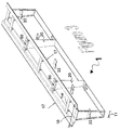
- the side walls of the separator are interconnected, on at least a substantial part of their height, by at least one rigid structure extending in a plane substantially vertical transverse, for example essentially constituted by a flat plate; each separator can have several plates (marked 20, Figures 2, 3, 14, 15) vertical regularly spaced by distance close to 1 to 3 meters; alternatively, reinforcements can be provided transverse in the form of vertical transverse plates arranged in alternating with horizontal transverse plates (marked 21 to 23) extending substantially halfway up the body of the separator, these reinforcements being spaced 1 to 2 meters apart.
- This transverse reinforcement structure allows during a shock of transmit the forces of a first side wall (left or right) (1d) to a second side wall (respectively right or left) and by consistent with the basic structure comprising the soles and their parts transverse connection, which allows better distribution of the forces in the structure of the separator, and therefore to better transmit the forces to the ground, and resist lateral crushing upon impact.
- these transverse reinforcements extend at least in the lower half of the separator, are arranged opposite (that is to say above) of said rigid connection means (1w) which connect the soles, and are rigidly linked (in particular welded) to these connections rigid sole; thus, the forces to which a wall is subjected lateral are transmitted effectively, not only to the lateral wall opposite, but also to the ground, by means of said means of rigid connection as well as by the bent soles equipping the ends lower side of the separator.
- transverse structures reinforcement these extend in particular at the two ends of the separator, and are rigidly linked to the means of connection of two separating sections (or elements); for example, these transverse (end) structures have a thick plate anchor for connecting rods (male) and a thick plate associated with female connecting members, and / or include bars (marked 25, Figure 15) extending along the internal face of the side walls and of the separator.
- the transverse connecting pieces attached to the soles which are flush with the underside of the soles and which therefore rest on the ground, can be provided with one or more orifice (s) allowing the handling of the separator (returned) by a lifting device, and / or allowing the passage through the connecting piece of a pin for anchoring a separator in the ground.
- the improvement in the rigidity of the separator body allows, equal performance, use a thinner sheet than usual provided, in particular a sheet whose thickness is within a range ranging from 2 to 4 millimeters, in particular a sheet of thickness close to 2.5 to 3.5 millimeters.
- Figure 1 illustrates in schematic cross-section, the structure of a separator equipped with two angled longitudinal flanges and transverse connection means.
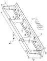
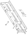
- Figures 2 and 13 to 15 illustrate in schematic perspective view four alternative embodiments of a separator according to the invention; the Figure 3 illustrates in perspective view in the inverted position the separator in Figure 2.
- Figures 4 to 7 illustrate four alternative embodiments of the pads and means of connection between soles, in partial right perspective view ( Figures 4, 5, 7) or turned over ( Figure 6).
- Figures 8, 9 and 13 illustrate anchoring devices to the ground of separators according to the invention
- Figure 9 is a perspective view exploded anchoring means.
- Figures 10 to 12 illustrate a partial perspective view of a separator part according to the invention.
- the wall elements 1c, 1d, 1e are preferably obtained by folding of a sheet of steel 3 or 4 millimeters thick, according to folding radii 16, 30 of a value close to 5 millimeters.
- the separator 1 has a continuous 3 mm (2.5 to 4 mm) sheet metal body on its periphery (to increase its resistance to torsion), closed on its entire height comprising a substantially vertical body with a grip at ground 10 reduced (less than or equal to 600 millimeters), with a width 11 of head equal to 20 to 25% of its height 12; the walls 1d form an angle (90-B) 5 degrees with vertical and 1c side overhangs (soles) are folded with a radius of 5 millimeters making an angle A of 19.5 degrees with the horizontal.
- the lateral overhangs (soles) have at their lateral end a hollow triangular tube shape of several centimeters thick and are stiffened and connected by a massive 1w bar connecting the overhangs located on each side.
- the structure of the separator body is all the more reinforced since, on the one hand the wall 1d close to the vertical is stiffened by the wall 1c substantially perpendicular, close to the horizontal, that on the other hand the wall 1c adjacent to the horizontal is itself stiffened by the reinforcement 1n, 1m in hollow edge tube, and finally the lower walls are embedded to each other via a 1w cross-link piece massive.
- the walls therefore all participate in the resistance to bending, considerably increasing the inertia of the separator.
- the rigid connection consists of solid bars 1w (FIG. 4) comprising a steel section of 5 cm 2 in contact with the bottom of the walls 1d of the separator, they are welded directly without adding a rib; otherwise, a rib (14, Figures 5, 6) oriented along the axis of the separator is provided; in the case of using hollow tubes ( Figure 7), gussets (14, Figures 5, 6) providing a connection of 5 cm 2 in section are provided between the bottom of the walls (1d) of the separator and the hollow tube 1w .
- Cross reinforcements (20, Figures 14, 15 in particular) extend substantially over the entire height of the main side walls and are fixed in the lower part (by a steel section of 5 cm 2 so as to be able to transmit a compressive force of several tonnes, preferably 10 tonnes) to skids (or rigid transverse bars 1w) carrying on the ground.
- the pads are preferably provided on their underside with a product (or coating 26, Figure 6) with a very high coefficient of friction on the ground.
- the structure of the separator thus comprises an uninterrupted chain of elements operating in compression between the face where the vehicle strikes and the ground support.
- the elements transverse profile, wall, bar, shoe
- the elements are linked to each other to transmit force by 5 cm 2 of steel section (approximately).
- the separators illustrated in Figures 2 and 15 have the particularity to have the edges of the longitudinal ends (contact with the neighboring separator) reinforced by 10 mm thick plates approximately, fixed by welding points.
- This arrangement makes it easier to resist handling; when vehicle impact, mismatches between a separator and the next are decreased.
- the separator has the particularity of having organs constituting two lifting rings in the upper and lower part for gripping the separator, in normal position and in position turned over, with slings closing on the ring; the organs of handling arranged in the lower part are obtained by the presence an orifice 50 ( Figures 3, 6) drilled in the bar 1w; organs arranged in the upper part are obtained by the presence of an orifice 51 ( Figures 2, 13) adjoining the orifice 40 - orifices provided in the wall 1e -, and by a bar 52 reinforcing the portion of the wall 1e extending between these holes; this arrangement improves safety and faster assembly and disassembly.
- the separator has the particularity of having holes 40, figure 13, in the upper and middle part making it possible to superimpose a additional security barrier such as an opaque screen 41 (FIG. 15), which is provided with two vertical bars 42 engaging in two holes 40 superimposed, respectively provided in the upper wall 1e and in the reinforcement piece 23; this arrangement makes it possible to put and remove a barrier with very simple fixing devices.
- a additional security barrier such as an opaque screen 41 (FIG. 15)
- the invention relates to an improved device of attachment to the separator floor, which is illustrated in FIGS. 8, 9 and 13;
- the device comprises several pins 60 (or piles) comprising two separable parts: a first part 61 of cylindrical spindle provided with its lower end with a tip 63 and provided at its second end (upper) of a threaded portion 64 allowing the connection by screwing of a second part 62, the cylindrical body of the first part 61 being of diameter between 10 and 100 millimeters, in particular of around 30 to 70 millimeters, which part is intended to be planted at remains in the ground, substantially flush with its upper end ; a second part 62 which has a complementary threaded part of the threaded part 64, which has a head 65, for example hexagonal able to cooperate with a screwing tool such as a wrench, and which includes a transverse orifice 66 horizontal for the passage of a key or screw 67;
- the separating element comprises a rigid transverse bar 1w provided with a orific
Landscapes
- Engineering & Computer Science (AREA)
- Architecture (AREA)
- Civil Engineering (AREA)
- Structural Engineering (AREA)
- Refuge Islands, Traffic Blockers, Or Guard Fence (AREA)
- Pit Excavations, Shoring, Fill Or Stabilisation Of Slopes (AREA)
Applications Claiming Priority (2)
| Application Number | Priority Date | Filing Date | Title |
|---|---|---|---|
| FR9814502 | 1998-11-13 | ||
| FR9814502A FR2785920A1 (fr) | 1998-11-13 | 1998-11-13 | Amelioration aux elements de barriere deplacables |
Publications (2)
| Publication Number | Publication Date |
|---|---|
| EP1001090A2 true EP1001090A2 (de) | 2000-05-17 |
| EP1001090A3 EP1001090A3 (de) | 2002-11-27 |
Family
ID=9532882
Family Applications (1)
| Application Number | Title | Priority Date | Filing Date |
|---|---|---|---|
| EP99430030A Withdrawn EP1001090A3 (de) | 1998-11-13 | 1999-11-12 | Umstellbare Barriere-Elemente |
Country Status (3)
| Country | Link |
|---|---|
| EP (1) | EP1001090A3 (de) |
| DE (1) | DE19953566A1 (de) |
| FR (1) | FR2785920A1 (de) |
Cited By (8)
| Publication number | Priority date | Publication date | Assignee | Title |
|---|---|---|---|---|
| NL1020420C2 (nl) * | 2002-04-18 | 2003-10-21 | Laura Metaal Eygelshoven B V | Barrierelement. |
| WO2008062196A1 (en) * | 2006-11-21 | 2008-05-29 | Hill & Smith Holdings Plc | Crash barrier beam |
| WO2009046695A1 (de) * | 2007-10-08 | 2009-04-16 | Heintzmann Sicherheitssysteme Gmbh & Co. Kg | Fahrzeugrückhaltesystem |
| ES2327589A1 (es) * | 2007-03-21 | 2009-10-30 | Laura Metaal Eygelshoven Bv | Elemento de barrera. |
| FR3029220A1 (fr) * | 2014-12-02 | 2016-06-03 | Aximum | Dispositif de retenue modulaire metallique pour des voies routieres, module et procede de pose |
| EP2635744B1 (de) * | 2010-11-04 | 2018-07-04 | Cir Ambiente S.p.A. | Barriere |
| IT201700101468A1 (it) * | 2017-09-11 | 2019-03-11 | Ticopter Sa | Barriera stradale |
| CN111472306A (zh) * | 2020-01-22 | 2020-07-31 | 安徽省交通控股集团有限公司 | 一种易于提高安装精确度的混凝土护栏 |
Families Citing this family (2)
| Publication number | Priority date | Publication date | Assignee | Title |
|---|---|---|---|---|
| DE102007048303B4 (de) * | 2007-10-08 | 2016-07-21 | Bochumer Eisenhütte Heintzmann GmbH & Co. Bau- und Beteiligungs KG | Fahrzeugrückhaltesystem |
| NL2022924B1 (en) | 2019-04-11 | 2020-10-20 | Laura Metaal Holding B V | Friction-increasing element for attachment to a roadblock, and roadblock provided with at least one such friction-increasing element |
Family Cites Families (7)
| Publication number | Priority date | Publication date | Assignee | Title |
|---|---|---|---|---|
| DE3106047C2 (de) * | 1981-02-19 | 1983-01-13 | Günther Dipl.-Ing. 6300 Gießen Förster | "Leitbegrenzung für eine Fahrbahn" |
| DE9101726U1 (de) * | 1991-02-14 | 1991-05-16 | SPS Schutzplanken GmbH, 8750 Aschaffenburg | Schutzplankeneinrichtung für Verkehrsflächen, insbesondere zur Sicherung von Baustellen |
| DE4032731C2 (de) | 1990-10-15 | 1994-11-10 | Sps Schutzplanken Gmbh | Auflage für zweiseitig wirkende Fertigteile einer Gleit- oder Schutzplankenvorrichtung für Verkehrswege |
| IT229150Y1 (it) * | 1992-04-14 | 1998-07-02 | Stori Leopoldo Gasparetto | Barriera metallica di sicurezza |
| DE4403438C2 (de) * | 1994-02-04 | 1998-01-15 | Nissen Adolf Elektrobau | Leitwand für Kraftfahrzeuge |
| DE19539274C2 (de) * | 1995-10-21 | 2001-10-18 | Spig Schutzplanken Prod Gmbh | Ablenkschwelle |
| FR2749329B1 (fr) * | 1996-06-04 | 1998-07-24 | Plattard Sa | Barriere de securite pour voies routieres et autoroutieres |
-
1998
- 1998-11-13 FR FR9814502A patent/FR2785920A1/fr active Pending
-
1999
- 1999-11-08 DE DE1999153566 patent/DE19953566A1/de not_active Withdrawn
- 1999-11-12 EP EP99430030A patent/EP1001090A3/de not_active Withdrawn
Cited By (19)
| Publication number | Priority date | Publication date | Assignee | Title |
|---|---|---|---|---|
| NL1020420C2 (nl) * | 2002-04-18 | 2003-10-21 | Laura Metaal Eygelshoven B V | Barrierelement. |
| WO2003087480A1 (en) * | 2002-04-18 | 2003-10-23 | Laura Metaal Eygelshoven Bv | Barrier element |
| GB2403500A (en) * | 2002-04-18 | 2005-01-05 | Laura Metaal Eygelshoven Bv | Barrier element |
| GB2403500B (en) * | 2002-04-18 | 2005-09-07 | Laura Metaal Eygelshoven Bv | Barrier element |
| US7226236B2 (en) | 2002-04-18 | 2007-06-05 | Laura Metaal Eygelshoven Bv | Barrier element |
| AU2007323210B2 (en) * | 2006-11-21 | 2013-07-25 | Hill & Smith Holdings Plc | Crash barrier beam |
| US8061926B2 (en) | 2006-11-21 | 2011-11-22 | Hill & Smith Limited | Crash barrier beam |
| WO2008062196A1 (en) * | 2006-11-21 | 2008-05-29 | Hill & Smith Holdings Plc | Crash barrier beam |
| GB2447531B (en) * | 2006-11-21 | 2012-01-18 | Hill & Smith Holdings Plc | Crash barrier beam |
| GB2447531A (en) * | 2006-11-21 | 2008-09-17 | Hill & Smith Holdings Plc | Crash barrier beam |
| ES2327589B1 (es) * | 2007-03-21 | 2010-08-04 | Laura Metaal Eygelshoven Bv | Elemento de barrera. |
| ES2327589A1 (es) * | 2007-03-21 | 2009-10-30 | Laura Metaal Eygelshoven Bv | Elemento de barrera. |
| WO2009046695A1 (de) * | 2007-10-08 | 2009-04-16 | Heintzmann Sicherheitssysteme Gmbh & Co. Kg | Fahrzeugrückhaltesystem |
| EP2635744B1 (de) * | 2010-11-04 | 2018-07-04 | Cir Ambiente S.p.A. | Barriere |
| FR3029220A1 (fr) * | 2014-12-02 | 2016-06-03 | Aximum | Dispositif de retenue modulaire metallique pour des voies routieres, module et procede de pose |
| EP3029202A1 (de) * | 2014-12-02 | 2016-06-08 | Aximum | Modulare rückhaltevorrichtung aus metall für verkehrswege, modul und installationsverfahren |
| IT201700101468A1 (it) * | 2017-09-11 | 2019-03-11 | Ticopter Sa | Barriera stradale |
| EP3453801A1 (de) * | 2017-09-11 | 2019-03-13 | Ticopter Sa | Strassenbarriere |
| CN111472306A (zh) * | 2020-01-22 | 2020-07-31 | 安徽省交通控股集团有限公司 | 一种易于提高安装精确度的混凝土护栏 |
Also Published As
| Publication number | Publication date |
|---|---|
| DE19953566A1 (de) | 2000-05-18 |
| FR2785920A1 (fr) | 2000-05-19 |
| EP1001090A3 (de) | 2002-11-27 |
Similar Documents
| Publication | Publication Date | Title |
|---|---|---|
| WO2008102080A1 (fr) | Dispositif modulable automatique qui forme une structure haute a l'arriere d'un vehicule automobile ou qui se compacte derriere les sieges avants | |
| CA2324941C (fr) | Separateur et barriere de protection ou de delimitation, par exemple pour voie de circulation automobile | |
| FR2481248A1 (fr) | Elements de fleche legers et resistants pour fleche de grue telescopique et fleche de grue formee de tels elements | |
| FR2479300A1 (fr) | Elements de barriere routiere, dispositif pour realiser une barriere routiere utilisant ces elements, et barriere routiere ainsi realisee | |
| FR2914332A1 (fr) | Structure de renforcement de cabine et cabine d'engin de travaux ainsi renforcee | |
| FR2785920A1 (fr) | Amelioration aux elements de barriere deplacables | |
| FR3011801A1 (fr) | Structure de bavolet de vehicule automobile | |
| FR2784344A1 (fr) | Plate-forme pour un vehicule utilitaire, chassis comprenant une telle plate-forme et vehicule utilitaire comprenant une telle plate-forme | |
| EP2392734A1 (de) | Fahrbahntrennmodul aus Beton und Trennbarriere, die mehrere Module dieses Typs umfasst | |
| CA2434606A1 (fr) | Dispositif de retenue modulaire et procede de pose d'un tel dispositif | |
| EP1561708A1 (de) | Demontierbare, modulare Bühne einer Müllsammeleinrichtung | |
| FR2785309A1 (fr) | Barriere de securite pour voies de circulation de vehicules, comprenant deux lisses superposees a resistances d'enfoncement differentielles | |
| FR2714406A1 (fr) | Elément-poutre préfabriqué pour la formation d'une barrière de sécurité pour voie de circulation routière et barrière obtenue. | |
| EP2431527B1 (de) | Kanaltrennelement und/oder Straßenbebakung und Kanaltrennungsbarriere | |
| FR2704823A1 (fr) | Chenille pour véhicule présentant des protubérances allongées. | |
| WO2022162288A1 (fr) | Structure de véhicule automobile | |
| FR2660677A1 (fr) | Dispositif de renfort de glissiere de securite metallique. | |
| EP1705315B1 (de) | Teleskopischer Unterstand | |
| FR2698650A1 (fr) | Passerelle pour le franchissement d'obstacle. | |
| EP0696976B1 (de) | Raupenkette mit einem band aus biegsamem material für ein fahrzeug | |
| FR2718689A1 (fr) | Châssis reconstitué en tôle pliée et soudée pour le maintien d'une benne à flancs convergents. | |
| FR2974584A1 (fr) | Porte d'ecluse | |
| FR2980492A1 (fr) | Poutre metallique adaptee pour former un element constitutif d'une travee d'un pont | |
| FR3141131A1 (fr) | planche à talon multicouche et alvéolée | |
| FR2874391A1 (fr) | Module de glissiere de securite et glissiere de securite correspondante |
Legal Events
| Date | Code | Title | Description |
|---|---|---|---|
| PUAI | Public reference made under article 153(3) epc to a published international application that has entered the european phase |
Free format text: ORIGINAL CODE: 0009012 |
|
| AK | Designated contracting states |
Kind code of ref document: A2 Designated state(s): AT BE CH CY DE DK ES FI FR GB GR IE IT LI LU MC NL PT SE |
|
| AX | Request for extension of the european patent |
Free format text: AL;LT;LV;MK;RO;SI |
|
| PUAL | Search report despatched |
Free format text: ORIGINAL CODE: 0009013 |
|
| AK | Designated contracting states |
Kind code of ref document: A3 Designated state(s): AT BE CH CY DE DK ES FI FR GB GR IE IT LI LU MC NL PT SE |
|
| AX | Request for extension of the european patent |
Free format text: AL;LT;LV;MK;RO;SI |
|
| RIC1 | Information provided on ipc code assigned before grant |
Free format text: 7E 01F 15/08 A, 7E 01F 15/04 B |
|
| 17P | Request for examination filed |
Effective date: 20030523 |
|
| AKX | Designation fees paid |
Designated state(s): AT BE CH CY DE DK ES FI FR GB GR IE IT LI LU MC NL PT SE |
|
| AXX | Extension fees paid |
Extension state: RO Payment date: 20030523 |
|
| 17Q | First examination report despatched |
Effective date: 20040803 |
|
| STAA | Information on the status of an ep patent application or granted ep patent |
Free format text: STATUS: THE APPLICATION IS DEEMED TO BE WITHDRAWN |
|
| 18D | Application deemed to be withdrawn |
Effective date: 20041214 |