EP1001145A2 - Verfahren zur Optimierung der Gemischbildung eines schnellaufenden direkteinspritzenden Dieselmotors sowie ein nach diesem Verfahren betriebener Dieselmotor - Google Patents
Verfahren zur Optimierung der Gemischbildung eines schnellaufenden direkteinspritzenden Dieselmotors sowie ein nach diesem Verfahren betriebener Dieselmotor Download PDFInfo
- Publication number
- EP1001145A2 EP1001145A2 EP99121848A EP99121848A EP1001145A2 EP 1001145 A2 EP1001145 A2 EP 1001145A2 EP 99121848 A EP99121848 A EP 99121848A EP 99121848 A EP99121848 A EP 99121848A EP 1001145 A2 EP1001145 A2 EP 1001145A2
- Authority
- EP
- European Patent Office
- Prior art keywords
- charge
- swirl
- channel
- cylinder
- air density
- Prior art date
- Legal status (The legal status is an assumption and is not a legal conclusion. Google has not performed a legal analysis and makes no representation as to the accuracy of the status listed.)
- Granted
Links
Images
Classifications
-
- F—MECHANICAL ENGINEERING; LIGHTING; HEATING; WEAPONS; BLASTING
- F02—COMBUSTION ENGINES; HOT-GAS OR COMBUSTION-PRODUCT ENGINE PLANTS
- F02B—INTERNAL-COMBUSTION PISTON ENGINES; COMBUSTION ENGINES IN GENERAL
- F02B31/00—Modifying induction systems for imparting a rotation to the charge in the cylinder
- F02B31/04—Modifying induction systems for imparting a rotation to the charge in the cylinder by means within the induction channel, e.g. deflectors
- F02B31/06—Movable means, e.g. butterfly valves
-
- Y—GENERAL TAGGING OF NEW TECHNOLOGICAL DEVELOPMENTS; GENERAL TAGGING OF CROSS-SECTIONAL TECHNOLOGIES SPANNING OVER SEVERAL SECTIONS OF THE IPC; TECHNICAL SUBJECTS COVERED BY FORMER USPC CROSS-REFERENCE ART COLLECTIONS [XRACs] AND DIGESTS
- Y02—TECHNOLOGIES OR APPLICATIONS FOR MITIGATION OR ADAPTATION AGAINST CLIMATE CHANGE
- Y02T—CLIMATE CHANGE MITIGATION TECHNOLOGIES RELATED TO TRANSPORTATION
- Y02T10/00—Road transport of goods or passengers
- Y02T10/10—Internal combustion engine [ICE] based vehicles
- Y02T10/12—Improving ICE efficiencies
Definitions
- the invention relates to a method according to the Preamble of claim 1 and a diesel engine according to the preamble of claim 3.
- DE 23 00 180 A1 describes a method for improving the mixture formation in the cylinder of a direct-injection diesel engine, in which the air flow before entry into the cylinder is at least partially caused to turbulence by dividing it into two or more partial flows and that these partial flows at an angle to each other to be brought together again to form a stream
- the cylinder charge can be mixed well overall, so that in particular areas with relative excess air and thus the formation of larger amounts of NOx can be avoided.
- a consideration of changing external factors or engine parameters on the combustion behavior of the cylinder charge is not possible.
- EP 0 214 251 B1 describes a direct-injection diesel engine with two intake and exhaust valves per cylinder, the intake valves being assigned an intake port, one of which is designed as a swirl port and the other as a filling port.
- An adjustable flow guide element is arranged in the filling channel, which can be adjusted depending on engine parameters so that it is closed in the partial load range and open in the full load range, a partial cross section of the filling channel remaining open, so that the air flow is influenced in such a way that the cylinder is reduced swirl-reducing charge air quantity and an increase in the charge air which increases the swirl and swirl.
- the swirl of the cylinder charge can thus be influenced as a function of engine parameters such as boost pressure, engine speed or injection quantity.
- the invention is based on the object Process to improve mixture formation to specify high-speed direct-injection diesel engines, through which in particular the disadvantageous Influence of changing external air pressure on the engine combustion in a generic diesel engine is avoidable.
- Claim 2 is the subject of a advantageous development of the method according to claim 1.
- the invention is also the object based on a generic diesel engine in this regard to improve that with changing air pressures reacts with greatly reduced black smoke formation. This further task is solved by the characteristics of the Claim 3.
- this throttle valve is activated via the engine control system depending on the air density or a substitute size representing the air density in the cylinder, such as the ambient air pressure, the boost pressure, the air temperature or the fresh air mass flow, each controlled as a function of engine speed and load, so that the charge swirl c u / c a increases with decreasing air density D. Due to the increased inlet swirl with decreasing air density, the air utilization during combustion is improved. With the same fuel injection mass, a reduction in the particles in the exhaust gas or a reduction in black smoke is achieved. The internal engine efficiency is improved.
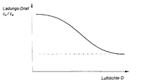
- the drawing shows a diagram of the dependence of the charge swirl c u / c a to be regulated on the air density D.
- the charge swirl is defined in the usual way by the ratio of the peripheral speed c u to the axial speed c a of the air in the cylinder.
- the diagram shows that at low air density D, z. B. when operating the diesel engine in an environment with low air pressure, a high charge swirl c u / c a must be adjusted.
- the air pressure can be measured in a manner known per se and compared with a table stored in the engine control, in which the external air pressure in connection with the speed and the load condition of the engine refers to an air density D in the cylinder.
- the passage through the filling channel is increasingly throttled by the engine control unit, so that the cylinder charge is increasingly sucked in through the swirl channel.
- This increases the charge swirl c u / c a in the desired manner and, despite the low air density D, the engine can be operated with a very low proportion of black smoke in the exhaust gas and with improved efficiency.
Landscapes
- Engineering & Computer Science (AREA)
- Chemical & Material Sciences (AREA)
- Combustion & Propulsion (AREA)
- Mechanical Engineering (AREA)
- General Engineering & Computer Science (AREA)
- Electrical Control Of Air Or Fuel Supplied To Internal-Combustion Engine (AREA)
- Combustion Methods Of Internal-Combustion Engines (AREA)
- Control Of Throttle Valves Provided In The Intake System Or In The Exhaust System (AREA)
Abstract
Description
Mit einer solchen Maßnahme kann zwar die Zylinderladung insgesamt gut durchmischt werden, so daß insbesondere Bereiche mit relativem Luftüberschuß und damit die Bildung größerer Mengen von NOx vermieden werden können. Eine Berücksichtigung von veränderlichen äußeren Faktoren oder motorischen Parametern auf das Brennverhalten der Zylinderladung ist damit aber nicht möglich.
Somit kann in Abhängigkeit von Motorparametern wie Ladedruck, Motordrehzahl oder Einspritzmenge der Drall der Zylinderladung beeinflußt werden.
Eine Beeinflussung der Zylinderladung und damit des Brennverhaltens der Ladung von äußeren Faktoren ist damit nicht vorgesehen. So ist z. B. zu beobachten, daß bei sonst optimal eingestellter Brennkraftmaschine infolge einer Veränderung des äußeren Luftdruckes, insbesondere der Absenkung des Luftdruckes z.B. durch Betreiben des Motors in größerer Höhe, wie dies bei Kraftfahrzeugen an Bergstrecken auftritt, eine erhöhte Schwarzrauchbildung eintritt.
Durch den erhöhten Einlaßdrall bei absinkender Luftdichte wird die Luftausnutzung bei der Verbrennung verbessert. Bei gleicher Kraftstoff-Einspritzmasse wird damit eine Verringerung der Partikel im Abgas bzw. eine Reduzierung des Schwarzrauches erreicht. Der innermotorische Wirkungsgrad wird verbessert. Im Ergebnis ergeben sich günstigere Emmissionswerte und niedrigerer Kraftstoffverbrauch.
Bei einem definierten gleichbleibenden Schwarzrauchniveau wird durch ein Anheben des Ladungsdralls cu/ca bei Absinken der Luftdichte, z. B. in Höhenlagen, die maximal mögliche Einspritzmasse und damit das Drehmoment erhöht. Dies verbessert deutlich die Anfahrbarkeit sowie das gesamte Fahrverhalten eines mit einem erfindungsgemäßen Dieselmotor angetriebenen Kraftfahrzeuges in Höhenlagen.
Aus dem Diagramm geht hervor, daß bei geringer Luftdichte D, z. B. bei Betrieb des Dieselmotors in einer Umgebung mit geringem Luftdruck, ein hoher Ladungsdrall cu/ca einzuregeln ist. Dazu kann in an sich bekannter Weise der Luftdruck gemessen und mit einer in der Motorsteuerung gespeicherten Tabelle verglichen werden, in welcher der äußere Luftdruck in Verbindung mit der Drehzahl und dem Lastzustand des Motors auf eine Luftdichte D im Zylinder verweist. Bei Erkennen einer ausreichend geringen Luftdichte D im Zylinder wird vom Motorsteuergerät der Durchgang durch den Füllungskanal zunehmend gedrosselt, so daß die Zylinderladung zunehmend durch den Drallkanal angesaugt wird. Damit erhöht sich der Ladungsdrall cu/ca in gewünschter Weise und der Motor kann trotz geringer Luftdichte D mit einem sehr geringen Schwarzrauchanteil im Abgas und mit verbessertem Wirkungsgrad betrieben werden.
Claims (3)
- Verfahren zur Optimierung der Gemischbildung eines schnellaufenden direkteinspritzenden Dieselmotors mit mehreren Einlaßkanälen und mindestens einem Auslaßkanal pro Zylinder und mit Ventilen zum Öffnen und Schließen der Kanäle, wobei zumindest ein Einlaßkanal als Drallkanal und mindestens ein weiterer Einlaßkanal als Füllungskanal ausgebildet sind und der bzw. die Füllungskanäle mittels Drosselelementen in ihrem Querschnitt von einem Motorsteuergerät veränderbar sind, so daß bei deren Drosselung ein grösserer Anteil der Ladung durch den bzw. die Drallkanäle in den Zylinder gelangt und so den Ladungsdrall cu/ca erhöht, dadurch gekennzeichnet, daß bei abnehmender Luftdichte D im Zylinder der Ladungsdrall cu/ca im Zylinder zunimmt und bei zunehmender Luftdichte D der Ladungsdrall cu/ca abnimmt.
- Verfahren nach Anspruch 1, dadurch gekennzeichnet, daß der Ladungsdrall cu/ca in Abhängigkeit von der zunehmenden Luftdichte D auf einen Wert von ca. 15 % des maximalen Ladungsdralles cu/ca reduziert wird und dann bei weiter steigender Luftdichte D annähernd konstant bleibt.
- Schnellaufender direkteinspritzender Dieselmotor mit optimierter Gemischbildung mit mehreren Einlaßkanälen und mindestens einem Auslaßkanal pro Zylinder und mit Ventilen zum Öffnen und Schließen der Kanäle, wobei zumindest ein Einlaßkanal als Drallkanal und mindestens ein weiterer Einlaßkanal als Füllungskanal ausgebildet sind und der bzw. die Füllungskanäle mittels Drosselelementen in ihrem Querschnitt von einem Motorsteuergerät veränderbar sind, so daß bei deren Drosselung ein größerer Anteil der Ladung durch den bzw. die Drallkanäle in den Zylinder gelangt und so den Ladungsdrall cu/ca erhöht, dadurch gekennzeichnet, daß der bzw. die Füllungskanäle mit abnehmender Luftdichte D zunehmend gedrosselt sind, so daß der durch den bzw. die Drallkanäle einströmende Anteil der Ladung zunimmt, hingegen der Anteil des durch den bzw. die Füllungskanäle einströmenden Ladungsanteils abnimmt und so der Ladungsdrall cu/ca im Zylinder von einem Maximalwert bei niedriger Luftdichte D mit zunehmender Luftdichte D auf einen vorgegebenen Minimalwert zurückgeht.
Applications Claiming Priority (2)
| Application Number | Priority Date | Filing Date | Title |
|---|---|---|---|
| DE19851647A DE19851647A1 (de) | 1998-11-10 | 1998-11-10 | Verfahren zur Optimierung der Gemischbildung eines schnellaufenden direkteinspritzenden Dieselmotors sowie ein nach diesem Verfahren betriebener Dieselmotor |
| DE19851647 | 1998-11-10 |
Publications (3)
| Publication Number | Publication Date |
|---|---|
| EP1001145A2 true EP1001145A2 (de) | 2000-05-17 |
| EP1001145A3 EP1001145A3 (de) | 2001-02-07 |
| EP1001145B1 EP1001145B1 (de) | 2004-09-29 |
Family
ID=7887199
Family Applications (1)
| Application Number | Title | Priority Date | Filing Date |
|---|---|---|---|
| EP99121848A Expired - Lifetime EP1001145B1 (de) | 1998-11-10 | 1999-11-04 | Verfahren zur Optimierung der Gemischbildung eines schnellaufenden direkteinspritzenden Dieselmotors sowie ein nach diesem Verfahren betriebener Dieselmotor |
Country Status (2)
| Country | Link |
|---|---|
| EP (1) | EP1001145B1 (de) |
| DE (2) | DE19851647A1 (de) |
Family Cites Families (8)
| Publication number | Priority date | Publication date | Assignee | Title |
|---|---|---|---|---|
| AT326423B (de) * | 1972-01-11 | 1975-12-10 | List Hans | Brennkraftmaschine mit direkter einspritzung |
| DE3507767A1 (de) * | 1985-03-05 | 1986-09-11 | Knorr-Bremse AG, 8000 München | Ladungsdrall- und/oder -turbulenzeinrichtung fuer verbrennungsmotore |
| DE4205237C2 (de) * | 1992-02-21 | 1994-06-01 | Daimler Benz Ag | Einlaßkanal in einem Zylinderkopf einer Brennkraftmaschine mit mindestens zwei Einlaßventilen pro Zylinder |
| DE69504869T2 (de) * | 1994-12-15 | 1999-02-11 | Ford-Werke Ag, 50735 Koeln | Einlass-system für eine brennkraftmaschine |
| US5553580A (en) * | 1995-01-13 | 1996-09-10 | Ganoung; David P. | Stratified charge engines and method for their operation |
| DE19503378C1 (de) * | 1995-02-02 | 1996-05-23 | Josef Lehle | Kanalanordnung für ein Ventil |
| US5640941A (en) * | 1995-12-04 | 1997-06-24 | Ford Motor Company | Internal combustion engine with stratified charge and tumble motion |
| JPH10299537A (ja) * | 1997-04-28 | 1998-11-10 | Mazda Motor Corp | 筒内噴射型火花点火式エンジン |
-
1998
- 1998-11-10 DE DE19851647A patent/DE19851647A1/de not_active Withdrawn
-
1999
- 1999-11-04 DE DE59910642T patent/DE59910642D1/de not_active Expired - Lifetime
- 1999-11-04 EP EP99121848A patent/EP1001145B1/de not_active Expired - Lifetime
Also Published As
| Publication number | Publication date |
|---|---|
| DE19851647A1 (de) | 2000-05-11 |
| DE59910642D1 (de) | 2004-11-04 |
| EP1001145A3 (de) | 2001-02-07 |
| EP1001145B1 (de) | 2004-09-29 |
Similar Documents
| Publication | Publication Date | Title |
|---|---|---|
| DE2353925C3 (de) | Vorrichtung zur Überwachung und Steuerung von Verunreinigungen bei einer Verbrennungskraftmaschine | |
| DE69327210T2 (de) | Einlassluftanlage für Brennkraftmaschine | |
| DE69801891T2 (de) | Steuervorrichtung für abgasrückführungssystem in einer brennkraftmaschine | |
| DE4439918C2 (de) | Vorrichtung zur Zufuhr eines Kraftstoff/Luft-Gemisches zu einer Brennkraftmaschine | |
| DE102004032777A1 (de) | Vorrichtung zur Zuführung eines Gasgemisches zu Saugstutzen von Zylindern eines Verbrennungsmotors | |
| DE102004027337A1 (de) | Aufgeladenes Luftansaugsystem für eine Verbrennungskraftmaschine | |
| DE3607383A1 (de) | Verbrennungsmotor | |
| DE102009046120A1 (de) | Verfahren und Vorrichtung zum Befeuchten der Ansaugluft einer Verbrennungsmaschine | |
| DE19929956C2 (de) | Abgasrückführventil | |
| WO1993014306A1 (de) | Verfahren zum betrieb eines schiffsdieselmotors | |
| DE19855601C2 (de) | Steuereinrichtung für Direkteinspritzungsmotor | |
| DE102006054117A1 (de) | Im Teil- und Volllastbetrieb gesteuerte Kurbelgehäuse-Belüftung einer Brennkraftmaschine | |
| EP1067281B1 (de) | Fremdgezündete Hubkolbenbrennkraftmaschine | |
| EP1001145B1 (de) | Verfahren zur Optimierung der Gemischbildung eines schnellaufenden direkteinspritzenden Dieselmotors sowie ein nach diesem Verfahren betriebener Dieselmotor | |
| EP1001146B1 (de) | Verfahren zur Optimierung der Gemischbildung eines schnellaufenden direkteinspritzenden Dieselmotors sowie ein nach diesem Verfahren betriebener Dieselmotor | |
| DE19849272B4 (de) | Verfahren zur Diagnose eines Abgasrückführungs(AGR)-Systems eines Verbrennungsprozesses | |
| DE10051325B4 (de) | Brennkraftmaschine | |
| DE102004016260B4 (de) | Vorrichtung für fremdgezündete Gasmotoren | |
| DE602004005034T2 (de) | Verfahren zur geräuschansteuerung einer brennkraftmaschine | |
| DE602004005062T2 (de) | Vergaser | |
| EP1296053B1 (de) | Verfahren zum direkten Einspritzen von Kraftstoff in Form von zwei Einspritzungen mit unterschiedlichen Einspritzwinkeln und eine Steuereinrichtung zum Einspritzen | |
| DE4408880A1 (de) | Verfahren zur Einstellung eines gewünschten Mischungsverhältnisses von Kraftstoffmenge zu Ansaugluftmenge | |
| DE3033679A1 (de) | Viertakt-brennkraftmaschine | |
| DE102004021363B4 (de) | Verfahren zur Steuerung der Zylinderinnenströmung (Einlassdrall) an einer Brennkraftmaschine und direkt einspritzende Brennkraftmaschine | |
| DE102018211095A1 (de) | Verfahren zum Betreiben eines Kraftfahrzeugs und Kraftfahrzeug |
Legal Events
| Date | Code | Title | Description |
|---|---|---|---|
| PUAI | Public reference made under article 153(3) epc to a published international application that has entered the european phase |
Free format text: ORIGINAL CODE: 0009012 |
|
| AK | Designated contracting states |
Kind code of ref document: A2 Designated state(s): DE FR GB IT |
|
| AX | Request for extension of the european patent |
Free format text: AL;LT;LV;MK;RO;SI |
|
| PUAL | Search report despatched |
Free format text: ORIGINAL CODE: 0009013 |
|
| AK | Designated contracting states |
Kind code of ref document: A3 Designated state(s): AT BE CH CY DE DK ES FI FR GB GR IE IT LI LU MC NL PT SE |
|
| AX | Request for extension of the european patent |
Free format text: AL;LT;LV;MK;RO;SI |
|
| RIC1 | Information provided on ipc code assigned before grant |
Free format text: 7F 02B 3/06 A, 7F 02B 31/08 B |
|
| 17P | Request for examination filed |
Effective date: 20010711 |
|
| AKX | Designation fees paid |
Free format text: DE FR GB IT |
|
| GRAP | Despatch of communication of intention to grant a patent |
Free format text: ORIGINAL CODE: EPIDOSNIGR1 |
|
| GRAS | Grant fee paid |
Free format text: ORIGINAL CODE: EPIDOSNIGR3 |
|
| GRAA | (expected) grant |
Free format text: ORIGINAL CODE: 0009210 |
|
| AK | Designated contracting states |
Kind code of ref document: B1 Designated state(s): DE FR GB IT |
|
| REG | Reference to a national code |
Ref country code: GB Ref legal event code: FG4D Free format text: NOT ENGLISH |
|
| REF | Corresponds to: |
Ref document number: 59910642 Country of ref document: DE Date of ref document: 20041104 Kind code of ref document: P |
|
| GBT | Gb: translation of ep patent filed (gb section 77(6)(a)/1977) |
Effective date: 20050115 |
|
| ET | Fr: translation filed | ||
| PLBE | No opposition filed within time limit |
Free format text: ORIGINAL CODE: 0009261 |
|
| STAA | Information on the status of an ep patent application or granted ep patent |
Free format text: STATUS: NO OPPOSITION FILED WITHIN TIME LIMIT |
|
| 26N | No opposition filed |
Effective date: 20050630 |
|
| REG | Reference to a national code |
Ref country code: GB Ref legal event code: 732E Free format text: REGISTERED BETWEEN 20090219 AND 20090225 |
|
| REG | Reference to a national code |
Ref country code: GB Ref legal event code: 732E Free format text: REGISTERED BETWEEN 20090305 AND 20090311 |
|
| REG | Reference to a national code |
Ref country code: GB Ref legal event code: 732E Free format text: REGISTERED BETWEEN 20091029 AND 20091104 |
|
| REG | Reference to a national code |
Ref country code: GB Ref legal event code: 732E Free format text: REGISTERED BETWEEN 20091105 AND 20091111 |
|
| REG | Reference to a national code |
Ref country code: DE Ref legal event code: R081 Ref document number: 59910642 Country of ref document: DE Owner name: GM GLOBAL TECHNOLOGY OPERATIONS LLC (N. D. GES, US Free format text: FORMER OWNER: GM GLOBAL TECHNOLOGY OPERATIONS, INC., DETROIT, MICH., US Effective date: 20110323 |
|
| PGFP | Annual fee paid to national office [announced via postgrant information from national office to epo] |
Ref country code: DE Payment date: 20121031 Year of fee payment: 14 |
|
| PGFP | Annual fee paid to national office [announced via postgrant information from national office to epo] |
Ref country code: IT Payment date: 20121110 Year of fee payment: 14 Ref country code: GB Payment date: 20121031 Year of fee payment: 14 |
|
| REG | Reference to a national code |
Ref country code: DE Ref legal event code: R119 Ref document number: 59910642 Country of ref document: DE |
|
| GBPC | Gb: european patent ceased through non-payment of renewal fee |
Effective date: 20131104 |
|
| PG25 | Lapsed in a contracting state [announced via postgrant information from national office to epo] |
Ref country code: IT Free format text: LAPSE BECAUSE OF NON-PAYMENT OF DUE FEES Effective date: 20131104 Ref country code: DE Free format text: LAPSE BECAUSE OF NON-PAYMENT OF DUE FEES Effective date: 20140603 |
|
| REG | Reference to a national code |
Ref country code: DE Ref legal event code: R119 Ref document number: 59910642 Country of ref document: DE Effective date: 20140603 |
|
| PG25 | Lapsed in a contracting state [announced via postgrant information from national office to epo] |
Ref country code: GB Free format text: LAPSE BECAUSE OF NON-PAYMENT OF DUE FEES Effective date: 20131104 |
|
| REG | Reference to a national code |
Ref country code: FR Ref legal event code: PLFP Year of fee payment: 17 |
|
| PGFP | Annual fee paid to national office [announced via postgrant information from national office to epo] |
Ref country code: FR Payment date: 20151008 Year of fee payment: 17 |
|
| REG | Reference to a national code |
Ref country code: FR Ref legal event code: ST Effective date: 20170731 |
|
| PG25 | Lapsed in a contracting state [announced via postgrant information from national office to epo] |
Ref country code: FR Free format text: LAPSE BECAUSE OF NON-PAYMENT OF DUE FEES Effective date: 20161130 |