EP1001203B1 - Poignée rotative pour un robinet sanitaire - Google Patents
Poignée rotative pour un robinet sanitaire Download PDFInfo
- Publication number
- EP1001203B1 EP1001203B1 EP99122444A EP99122444A EP1001203B1 EP 1001203 B1 EP1001203 B1 EP 1001203B1 EP 99122444 A EP99122444 A EP 99122444A EP 99122444 A EP99122444 A EP 99122444A EP 1001203 B1 EP1001203 B1 EP 1001203B1
- Authority
- EP
- European Patent Office
- Prior art keywords
- stop
- handle
- arrangement according
- stop element
- assigned
- Prior art date
- Legal status (The legal status is an assumption and is not a legal conclusion. Google has not performed a legal analysis and makes no representation as to the accuracy of the status listed.)
- Expired - Lifetime
Links
- 238000009428 plumbing Methods 0.000 claims 3
- 238000011161 development Methods 0.000 description 5
- 230000018109 developmental process Effects 0.000 description 5
- 230000001419 dependent effect Effects 0.000 description 1
- 238000004519 manufacturing process Methods 0.000 description 1
- XLYOFNOQVPJJNP-UHFFFAOYSA-N water Substances O XLYOFNOQVPJJNP-UHFFFAOYSA-N 0.000 description 1
Images

Classifications
-
- F—MECHANICAL ENGINEERING; LIGHTING; HEATING; WEAPONS; BLASTING
- F16—ENGINEERING ELEMENTS AND UNITS; GENERAL MEASURES FOR PRODUCING AND MAINTAINING EFFECTIVE FUNCTIONING OF MACHINES OR INSTALLATIONS; THERMAL INSULATION IN GENERAL
- F16K—VALVES; TAPS; COCKS; ACTUATING-FLOATS; DEVICES FOR VENTING OR AERATING
- F16K35/00—Means to prevent accidental or unauthorised actuation
- F16K35/02—Means to prevent accidental or unauthorised actuation to be locked or disconnected by means of a pushing or pulling action
- F16K35/022—Means to prevent accidental or unauthorised actuation to be locked or disconnected by means of a pushing or pulling action the locking mechanism being actuated by a separate actuating element
- F16K35/025—Means to prevent accidental or unauthorised actuation to be locked or disconnected by means of a pushing or pulling action the locking mechanism being actuated by a separate actuating element said actuating element being operated manually (e.g. a push-button located in the valve actuator)
Definitions
- a handle for a thermostatic valve wherein on the valve, a resilient stop member is formed, which can cooperate with a fixed stop surface of the handle together (US 4232817).
- the invention proposes a rotary handle with the features of claim 1. Further developments of the invention are the subject of the dependent claims, the wording of which is incorporated by reference into the content of the description.
- the overcoming of the stop can be done by an arbitrarily designed actuation of the actuating element, for example by a rotation of an accessible element on the rotary handle. It is particularly advantageous if the actuating element is acted upon by a spring in the position in which the two stops can cooperate.
- the stop surface of the valve associated with the connection element may be formed in a development of the invention in a direction approximately in the direction of rotation about the axis extending wall portion, so that the stop surface having the element of the handle associated stop member slidably abuts the wall section after overcoming the rotation limit.
- This wall section can serve to overcome any resistance when turning back the rotary handle.
- the wall section can be arranged coaxially with the axis of rotation.
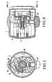
- a stop element 8 is fixed, which forms on its side facing the sanitary element 2 a sleeve with an internal toothing.
- This sleeve is closed by a bottom 9 having an opening 26 for the passage of the spindle.
- a stop surface 10 is formed, which extends approximately radially relative to the axis of the threaded spindle 6.
- the stop surface 10 has a radial distance from an inner sleeve 11, which surrounds the sleeve 5 of the handle with a small distance.
- a stop element 12 is slidably mounted, which has on its valve 2 side facing a stop member 13 with a stop surface 14.
- the stop surface 14 is in the axial direction at the same location as the stop surface 10 of the valve associated with the stop element 8. As seen in the circumferential direction, the stop surface 14 is also in the same place as the stop surface 10. If the stop element 12 in the position shown in Figure 1 turned counterclockwise in the direction of an opening of the valve, then passes after half a revolution, the stop surface 14 to rest against the stop surface 10. Thus, the rotational movement is limited.
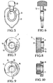
- Fig. 7 shows once again the wall portion 16 with the stop surface formed at its end 10, both of which are integrally formed on the bottom 9 of the valve 2 associated with the connecting element 8.
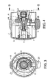
- FIGs. 3, 4, 9 and 10 show an embodiment in which after overcoming the Stop further rotation is also possible to a larger angle.
- the stop surface 10 is formed by the beginning of the wall portion 16, which is integrally formed on the bottom 9 of the valve associated with the stop element 8. In this case, however, the wall portion 16 is not connected to the inner sleeve 11 by means of a transverse web, but remains separated from the sleeve 11.
- the stop element assigned individually to the handle shown in FIG. 5 is inserted from the inside of the handle shell 1. This is made possible by the spring 18 with the long spring travel.
- the guide portion 21 is formed so that it surrounds the sleeve only partially.
- the guideway 21 is thus formed only on one side, so that the sleeve may indeed rest in both end positions on the guideway, but during the movement only on one side.
- the stop element shown in Fig. 11 can be inserted laterally through the opening whose diameter corresponds to the transverse dimension of the actuating knob 20.
Landscapes
- Engineering & Computer Science (AREA)
- General Engineering & Computer Science (AREA)
- Mechanical Engineering (AREA)
- Mechanically-Actuated Valves (AREA)
- Preventing Unauthorised Actuation Of Valves (AREA)
- Taps Or Cocks (AREA)
Claims (16)
- Agencement pour une soupape sanitaire (2) comprenant une poignée rotative, un élément de butée (8), une douille (5) et un élément de butée supplémentaire (12), l'un élément de butée (8) pouvant être mis dans une position angulaire fixe sur la soupape sanitaire et présentant une surface d'arrêt (10) s'étendant à peu près en direction radiale par rapport à l'axe de rotation de la tige de soupape (6),
la douille (5) étant prévue pour l'au moins raccordement résistant à la torsion avec la tige pivotante (6) de la soupape sanitaire (2) et l'élément de butée supplémentaire (12) étant maintenu de manière réglable sur la poignée rotative et présentant une surface d'arrêt (14) pouvant être mise en prise avec la surface d'arrêt (10) de l'élément de butée (8) côté soupape par rotation de la poignée rotative, caractérisé en ce que l'élément de butée (12) associé à la poignée rotative est mené sur la douille (5) et présente une section de guidage (21) à laquelle la douille (5) est adjacente au moins dans la position de butée de la butée (12) associée à la poignée et qui entoure la douille au moins en partie. - Agencement selon la revendication 1, dans lequel l'élément de butée (12) associé à la poignée est contraint par ressort dans une position dans laquelle la surface d'arrêt (10) de l'élément de butée (8) associé à la soupape (2) se trouve dans la trajectoire de sa surface d'arrêt (14), que celle-ci décrit lors de la rotation de la poignée rotative.
- Agencement selon la revendication 1 ou 2, dans lequel l'élément de butée (12) associé à la poignée est déplaçable à peu près en direction radiale par rapport à l'axe de rotation de la tige (6).
- Agencement selon l'une quelconque des revendications précédentes, dans lequel le ressort (18) est en matière plastique et est exécuté d'une seule pièce avec l'élément de butée (12) associé à la poignée rotative.
- Agencement selon l'une quelconque des revendications précédentes, dans lequel le ressort (18) est exécuté en étrier et s'appuie sur la poignée dans la zone d'un point diamétralement opposé à un élément de commande (20).
- Agencement selon la revendication 5, dans lequel le ressort (18) est exécuté de manière symétrique par rapport à une ligne raccordant l'élément de commande (20) au point d'appui.
- Agencement selon l'une quelconque des revendications précédentes, dans lequel la surface d'arrêt (10) de l'élément de butée (8) associé à la soupape (2) est exécutée sur une section murale (16), s'étendant à peu près dans la direction de rotation autour de l'axe de rotation, à laquelle section murale l'élément, présentant la surface d'arrêt (14), de l'élément de butée (12) associé à la poignée est adjacent de manière coulissante lorsqu'on continue de le tourner.
- Agencement selon la revendication 7, dans lequel la section murale (16) présente une nervure transversale (17) située dans la trajectoire de la surface d'arrêt (14).
- Agencement selon la revendication 7 ou 8, dans lequel la section murale (16) est exécutée de manière cylindrique.
- Agencement selon l'une quelconque des revendications 7 à 9, dans lequel la section murale (16) est disposée de manière coaxiale.
- Agencement selon l'un quelconque des revendications 7 à 9, dans lequel la section murale (16) est disposée de manière excentrique.
- Agencement selon la revendication 7 ou 8, dans lequel la section murale (16) est exécutée en forme de spirale.
- Agencement selon l'une quelconque des revendications 7 à 12, dans lequel la section murale (16), dans la partie de son extrémité (24) opposée à sa surface d'arrêt (10), s'étend de telle manière qu'elle n'est pas située dans la trajectoire de la surface d'arrêt (14) de l'élément de butée (12) associé à la poignée.
- Agencement selon l'une quelconque des revendications précédentes, dans lequel la section de guidage présente un orifice (22) de préférence fermé, à travers lequel la douille (5) a prise.
- Agencement selon la revendication 14, dans lequel la douille (5), dans les deux positions finales du mouvement de l'élément de butée (12) associé à la poignée, est adjacente au bord de l'orifice (22).
- Agencement selon la revendication 14 ou 15, dans lequel la douille (5), dans les deux positions finales du mouvement de l'élément de butée (12) associé à la poignée, est adjacente à la section de guidage (21), en particulier au bord de l'orifice (22).
Applications Claiming Priority (2)
| Application Number | Priority Date | Filing Date | Title |
|---|---|---|---|
| DE19852618A DE19852618A1 (de) | 1998-11-14 | 1998-11-14 | Drehgriff für ein Sanitärventil |
| DE19852618 | 1998-11-14 |
Publications (3)
| Publication Number | Publication Date |
|---|---|
| EP1001203A2 EP1001203A2 (fr) | 2000-05-17 |
| EP1001203A3 EP1001203A3 (fr) | 2001-05-02 |
| EP1001203B1 true EP1001203B1 (fr) | 2006-08-23 |
Family
ID=7887840
Family Applications (1)
| Application Number | Title | Priority Date | Filing Date |
|---|---|---|---|
| EP99122444A Expired - Lifetime EP1001203B1 (fr) | 1998-11-14 | 1999-11-11 | Poignée rotative pour un robinet sanitaire |
Country Status (6)
| Country | Link |
|---|---|
| EP (1) | EP1001203B1 (fr) |
| AT (1) | ATE337509T1 (fr) |
| DE (2) | DE19852618A1 (fr) |
| DK (1) | DK1001203T3 (fr) |
| ES (1) | ES2272031T3 (fr) |
| PT (1) | PT1001203E (fr) |
Families Citing this family (4)
| Publication number | Priority date | Publication date | Assignee | Title |
|---|---|---|---|---|
| DE102006045540A1 (de) * | 2006-09-25 | 2008-04-03 | Grohe Ag | Stellgriff für ein Wasserventil |
| DE102009021185B4 (de) * | 2009-05-13 | 2013-03-07 | Grohe Ag | Drehgriff für Sanitärarmatur |
| US9709189B2 (en) | 2014-02-28 | 2017-07-18 | Itt Manufacturing Enterprises Llc | Final position locking feature of multi-turn rotational device having an axially translating wheel or a clocked lock passage gear |
| DE102016209043B4 (de) | 2016-05-24 | 2019-05-09 | Hansgrohe Se | Ventildrehgriffvorrichtung und Thermostatventil |
Family Cites Families (7)
| Publication number | Priority date | Publication date | Assignee | Title |
|---|---|---|---|---|
| DE2737083C2 (de) * | 1977-08-17 | 1985-10-10 | Honeywell-Braukmann GmbH, 6950 Mosbach | Heizkörperventil |
| DE3530812A1 (de) * | 1985-08-29 | 1987-03-05 | Grohe Armaturen Friedrich | Stellvorrichtung fuer ein thermostatisch geregeltes mischventil |
| DE4123856A1 (de) * | 1991-07-18 | 1993-01-21 | Grohe Armaturen Friedrich | Stellvorrichtung fuer ein mischventil |
| DE9300841U1 (de) * | 1993-01-22 | 1993-03-11 | Hans Grohe Gmbh & Co Kg, 7622 Schiltach | Sanitärarmatur |
| DE4308762A1 (de) * | 1993-03-19 | 1994-09-22 | Grohe Armaturen Friedrich | Mengenregulierventil |
| DE4417485C2 (de) * | 1994-05-19 | 1997-08-28 | Hansa Metallwerke Ag | Sanitärarmatur |
| DE19702360A1 (de) * | 1997-01-23 | 1998-07-30 | Grohe Kg Hans | Betätigungsgriff für ein Sanitärelement |
-
1998
- 1998-11-14 DE DE19852618A patent/DE19852618A1/de not_active Withdrawn
-
1999
- 1999-11-11 AT AT99122444T patent/ATE337509T1/de not_active IP Right Cessation
- 1999-11-11 EP EP99122444A patent/EP1001203B1/fr not_active Expired - Lifetime
- 1999-11-11 PT PT99122444T patent/PT1001203E/pt unknown
- 1999-11-11 DE DE59913794T patent/DE59913794D1/de not_active Expired - Lifetime
- 1999-11-11 DK DK99122444T patent/DK1001203T3/da active
- 1999-11-11 ES ES99122444T patent/ES2272031T3/es not_active Expired - Lifetime
Also Published As
| Publication number | Publication date |
|---|---|
| DE59913794D1 (de) | 2006-10-05 |
| PT1001203E (pt) | 2006-11-30 |
| DK1001203T3 (da) | 2006-12-18 |
| ES2272031T3 (es) | 2007-04-16 |
| EP1001203A3 (fr) | 2001-05-02 |
| EP1001203A2 (fr) | 2000-05-17 |
| DE19852618A1 (de) | 2000-05-18 |
| ATE337509T1 (de) | 2006-09-15 |
Similar Documents
| Publication | Publication Date | Title |
|---|---|---|
| EP1953311B1 (fr) | Agencement à ressort de rappel pour ferrures de porte ou de fenêtre ainsi que des ferrures de porte et/ou de fenêtre | |
| DE102004043898B3 (de) | Vorrichtung zum Sperren der Lenkspindel eines Kraftfahrzeugs | |
| EP2623828B1 (fr) | Robinet | |
| DE20103850U1 (de) | Schaltscharnier | |
| EP2251578B1 (fr) | Poignée rotative pour une armature sanitaire | |
| EP0683341B1 (fr) | Armature sanitaire | |
| EP1704353A1 (fr) | Robinet sanitaire | |
| EP1882798B1 (fr) | Ferrure pour porte ou fenêtre | |
| DE19852618A1 (de) | Drehgriff für ein Sanitärventil | |
| AT399242B (de) | Betätigungsvorrichtung für tastschalter mit drehbarer handhabe | |
| EP1217130A1 (fr) | Dispositif de fixation pour des parties de robinetterie sanitaire | |
| EP3354808A1 (fr) | Garniture d'évacuation pourvue de bouchon de vidange pouvant être soulevé et abaissé | |
| EP0774590B1 (fr) | Dispositif de tension pour câble de commande | |
| DE29620818U1 (de) | Arretiermechanismus | |
| CH638599A5 (de) | Absperrorgan mit einer betaetigungsvorrichtung. | |
| DE4105387C1 (fr) | ||
| EP1532913B1 (fr) | Dispositif d'amortissement de sièges de toilettes et/ou de couvercle de toilettes | |
| EP2226541B1 (fr) | Agencement d'actionnement pour armatures sanitaires | |
| DE4414887C2 (de) | Ab- und Überlaufarmatur für Badewannen | |
| DE10030699A1 (de) | Voreinstellbares Einbauventil | |
| DE9300841U1 (de) | Sanitärarmatur | |
| DE3340166C2 (fr) | ||
| EP1659322B1 (fr) | Poignée rotative pour des installations sanitaires | |
| EP3540156A1 (fr) | Palier de poignée | |
| DE102006035885B3 (de) | Hebelventil für eine Sanitärarmatur mit Kaltwasser- und Warmwasserzuläufen |
Legal Events
| Date | Code | Title | Description |
|---|---|---|---|
| PUAI | Public reference made under article 153(3) epc to a published international application that has entered the european phase |
Free format text: ORIGINAL CODE: 0009012 |
|
| AK | Designated contracting states |
Kind code of ref document: A2 Designated state(s): AT BE CH CY DE DK ES FI FR GB GR IE IT LI LU MC NL PT SE |
|
| AX | Request for extension of the european patent |
Free format text: AL;LT;LV;MK;RO;SI |
|
| PUAL | Search report despatched |
Free format text: ORIGINAL CODE: 0009013 |
|
| AK | Designated contracting states |
Kind code of ref document: A3 Designated state(s): AT BE CH CY DE DK ES FI FR GB GR IE IT LI LU MC NL PT SE |
|
| AX | Request for extension of the european patent |
Free format text: AL;LT;LV;MK;RO;SI |
|
| 17P | Request for examination filed |
Effective date: 20011004 |
|
| AKX | Designation fees paid |
Free format text: AT BE CH CY DE DK ES FI FR GB GR IE IT LI LU MC NL PT SE |
|
| 17Q | First examination report despatched |
Effective date: 20050405 |
|
| GRAP | Despatch of communication of intention to grant a patent |
Free format text: ORIGINAL CODE: EPIDOSNIGR1 |
|
| GRAS | Grant fee paid |
Free format text: ORIGINAL CODE: EPIDOSNIGR3 |
|
| GRAA | (expected) grant |
Free format text: ORIGINAL CODE: 0009210 |
|
| AK | Designated contracting states |
Kind code of ref document: B1 Designated state(s): AT BE CH CY DE DK ES FI FR GB GR IE IT LI LU MC NL PT SE |
|
| PG25 | Lapsed in a contracting state [announced via postgrant information from national office to epo] |
Ref country code: NL Free format text: LAPSE BECAUSE OF FAILURE TO SUBMIT A TRANSLATION OF THE DESCRIPTION OR TO PAY THE FEE WITHIN THE PRESCRIBED TIME-LIMIT Effective date: 20060823 Ref country code: IT Free format text: LAPSE BECAUSE OF FAILURE TO SUBMIT A TRANSLATION OF THE DESCRIPTION OR TO PAY THE FEE WITHIN THE PRESCRIBED TIME-LIMIT;WARNING: LAPSES OF ITALIAN PATENTS WITH EFFECTIVE DATE BEFORE 2007 MAY HAVE OCCURRED AT ANY TIME BEFORE 2007. THE CORRECT EFFECTIVE DATE MAY BE DIFFERENT FROM THE ONE RECORDED. Effective date: 20060823 Ref country code: IE Free format text: LAPSE BECAUSE OF FAILURE TO SUBMIT A TRANSLATION OF THE DESCRIPTION OR TO PAY THE FEE WITHIN THE PRESCRIBED TIME-LIMIT Effective date: 20060823 Ref country code: FI Free format text: LAPSE BECAUSE OF FAILURE TO SUBMIT A TRANSLATION OF THE DESCRIPTION OR TO PAY THE FEE WITHIN THE PRESCRIBED TIME-LIMIT Effective date: 20060823 |
|
| REG | Reference to a national code |
Ref country code: GB Ref legal event code: FG4D Free format text: NOT ENGLISH |
|
| REG | Reference to a national code |
Ref country code: CH Ref legal event code: NV Representative=s name: TROESCH SCHEIDEGGER WERNER AG Ref country code: CH Ref legal event code: EP |
|
| REG | Reference to a national code |
Ref country code: IE Ref legal event code: FG4D Free format text: LANGUAGE OF EP DOCUMENT: GERMAN |
|
| REF | Corresponds to: |
Ref document number: 59913794 Country of ref document: DE Date of ref document: 20061005 Kind code of ref document: P |
|
| GBT | Gb: translation of ep patent filed (gb section 77(6)(a)/1977) |
Effective date: 20061004 |
|
| PGFP | Annual fee paid to national office [announced via postgrant information from national office to epo] |
Ref country code: PT Payment date: 20061107 Year of fee payment: 8 |
|
| PG25 | Lapsed in a contracting state [announced via postgrant information from national office to epo] |
Ref country code: MC Free format text: LAPSE BECAUSE OF NON-PAYMENT OF DUE FEES Effective date: 20061130 Ref country code: BE Free format text: LAPSE BECAUSE OF NON-PAYMENT OF DUE FEES Effective date: 20061130 |
|
| REG | Reference to a national code |
Ref country code: PT Ref legal event code: SC4A Free format text: AVAILABILITY OF NATIONAL TRANSLATION Effective date: 20061006 |
|
| REG | Reference to a national code |
Ref country code: SE Ref legal event code: TRGR |
|
| NLV1 | Nl: lapsed or annulled due to failure to fulfill the requirements of art. 29p and 29m of the patents act | ||
| REG | Reference to a national code |
Ref country code: IE Ref legal event code: FD4D |
|
| ET | Fr: translation filed | ||
| REG | Reference to a national code |
Ref country code: ES Ref legal event code: FG2A Ref document number: 2272031 Country of ref document: ES Kind code of ref document: T3 |
|
| PLBE | No opposition filed within time limit |
Free format text: ORIGINAL CODE: 0009261 |
|
| STAA | Information on the status of an ep patent application or granted ep patent |
Free format text: STATUS: NO OPPOSITION FILED WITHIN TIME LIMIT |
|
| 26N | No opposition filed |
Effective date: 20070524 |
|
| BERE | Be: lapsed |
Owner name: HANSGROHE A.G. Effective date: 20061130 |
|
| PG25 | Lapsed in a contracting state [announced via postgrant information from national office to epo] |
Ref country code: AT Free format text: LAPSE BECAUSE OF NON-PAYMENT OF DUE FEES Effective date: 20061111 |
|
| PG25 | Lapsed in a contracting state [announced via postgrant information from national office to epo] |
Ref country code: GR Free format text: LAPSE BECAUSE OF FAILURE TO SUBMIT A TRANSLATION OF THE DESCRIPTION OR TO PAY THE FEE WITHIN THE PRESCRIBED TIME-LIMIT Effective date: 20061124 |
|
| REG | Reference to a national code |
Ref country code: PT Ref legal event code: MM4A Free format text: LAPSE DUE TO NON-PAYMENT OF FEES Effective date: 20080512 |
|
| PG25 | Lapsed in a contracting state [announced via postgrant information from national office to epo] |
Ref country code: LU Free format text: LAPSE BECAUSE OF NON-PAYMENT OF DUE FEES Effective date: 20061111 |
|
| PG25 | Lapsed in a contracting state [announced via postgrant information from national office to epo] |
Ref country code: PT Free format text: LAPSE BECAUSE OF NON-PAYMENT OF DUE FEES Effective date: 20080512 |
|
| PG25 | Lapsed in a contracting state [announced via postgrant information from national office to epo] |
Ref country code: CY Free format text: LAPSE BECAUSE OF FAILURE TO SUBMIT A TRANSLATION OF THE DESCRIPTION OR TO PAY THE FEE WITHIN THE PRESCRIBED TIME-LIMIT Effective date: 20060823 |
|
| PGFP | Annual fee paid to national office [announced via postgrant information from national office to epo] |
Ref country code: GB Payment date: 20101123 Year of fee payment: 12 |
|
| PGFP | Annual fee paid to national office [announced via postgrant information from national office to epo] |
Ref country code: CH Payment date: 20111124 Year of fee payment: 13 Ref country code: FR Payment date: 20111125 Year of fee payment: 13 Ref country code: DK Payment date: 20111124 Year of fee payment: 13 |
|
| REG | Reference to a national code |
Ref country code: DE Ref legal event code: R082 Ref document number: 59913794 Country of ref document: DE Representative=s name: PATENTANWAELTE RUFF, WILHELM, BEIER, DAUSTER &, DE |
|
| REG | Reference to a national code |
Ref country code: DE Ref legal event code: R082 Ref document number: 59913794 Country of ref document: DE Representative=s name: PATENTANWAELTE RUFF, WILHELM, BEIER, DAUSTER &, DE Effective date: 20120910 Ref country code: DE Ref legal event code: R081 Ref document number: 59913794 Country of ref document: DE Owner name: HANSGROHE SE, DE Free format text: FORMER OWNER: HANSGROHE AG, 77761 SCHILTACH, DE Effective date: 20120910 |
|
| PGFP | Annual fee paid to national office [announced via postgrant information from national office to epo] |
Ref country code: ES Payment date: 20121122 Year of fee payment: 14 Ref country code: IT Payment date: 20121123 Year of fee payment: 14 |
|
| REG | Reference to a national code |
Ref country code: CH Ref legal event code: PL |
|
| REG | Reference to a national code |
Ref country code: DK Ref legal event code: EBP |
|
| GBPC | Gb: european patent ceased through non-payment of renewal fee |
Effective date: 20121111 |
|
| PG25 | Lapsed in a contracting state [announced via postgrant information from national office to epo] |
Ref country code: LI Free format text: LAPSE BECAUSE OF NON-PAYMENT OF DUE FEES Effective date: 20121130 Ref country code: CH Free format text: LAPSE BECAUSE OF NON-PAYMENT OF DUE FEES Effective date: 20121130 |
|
| REG | Reference to a national code |
Ref country code: FR Ref legal event code: ST Effective date: 20130731 |
|
| PG25 | Lapsed in a contracting state [announced via postgrant information from national office to epo] |
Ref country code: DK Free format text: LAPSE BECAUSE OF NON-PAYMENT OF DUE FEES Effective date: 20121130 |
|
| PG25 | Lapsed in a contracting state [announced via postgrant information from national office to epo] |
Ref country code: GB Free format text: LAPSE BECAUSE OF NON-PAYMENT OF DUE FEES Effective date: 20121111 Ref country code: FR Free format text: LAPSE BECAUSE OF NON-PAYMENT OF DUE FEES Effective date: 20121130 |
|
| PG25 | Lapsed in a contracting state [announced via postgrant information from national office to epo] |
Ref country code: IT Free format text: LAPSE BECAUSE OF NON-PAYMENT OF DUE FEES Effective date: 20131111 |
|
| REG | Reference to a national code |
Ref country code: ES Ref legal event code: FD2A Effective date: 20150529 |
|
| PG25 | Lapsed in a contracting state [announced via postgrant information from national office to epo] |
Ref country code: ES Free format text: LAPSE BECAUSE OF NON-PAYMENT OF DUE FEES Effective date: 20131112 |
|
| PGFP | Annual fee paid to national office [announced via postgrant information from national office to epo] |
Ref country code: SE Payment date: 20161124 Year of fee payment: 18 |
|
| REG | Reference to a national code |
Ref country code: SE Ref legal event code: EUG |
|
| PG25 | Lapsed in a contracting state [announced via postgrant information from national office to epo] |
Ref country code: SE Free format text: LAPSE BECAUSE OF NON-PAYMENT OF DUE FEES Effective date: 20171112 |
|
| PGFP | Annual fee paid to national office [announced via postgrant information from national office to epo] |
Ref country code: DE Payment date: 20181126 Year of fee payment: 20 |
|
| REG | Reference to a national code |
Ref country code: DE Ref legal event code: R071 Ref document number: 59913794 Country of ref document: DE |