EP1001220A2 - Bougie à tige incandescente - Google Patents
Bougie à tige incandescente Download PDFInfo
- Publication number
- EP1001220A2 EP1001220A2 EP99121240A EP99121240A EP1001220A2 EP 1001220 A2 EP1001220 A2 EP 1001220A2 EP 99121240 A EP99121240 A EP 99121240A EP 99121240 A EP99121240 A EP 99121240A EP 1001220 A2 EP1001220 A2 EP 1001220A2
- Authority
- EP
- European Patent Office
- Prior art keywords
- connection
- glow
- plug
- glow plug
- heating element
- Prior art date
- Legal status (The legal status is an assumption and is not a legal conclusion. Google has not performed a legal analysis and makes no representation as to the accuracy of the status listed.)
- Granted
Links
Images

Classifications
-
- F—MECHANICAL ENGINEERING; LIGHTING; HEATING; WEAPONS; BLASTING
- F23—COMBUSTION APPARATUS; COMBUSTION PROCESSES
- F23Q—IGNITION; EXTINGUISHING-DEVICES
- F23Q7/00—Incandescent ignition; Igniters using electrically-produced heat, e.g. lighters for cigarettes; Electrically-heated glowing plugs
- F23Q7/001—Glowing plugs for internal-combustion engines
Definitions
- the invention relates to glow plugs with electrical control for Ion current measurement, clocking and for sensor functionalization.
- the object of the invention is that known from the prior art and overcome listed disadvantages; in particular it also applies in the case of a mass-free glow plug, for example a ground line for ion current measurement to make it unnecessary back to the control unit; equally one for Vehicle electrical system voltage of, for example, 14 volts of glow plug on one Vehicle electrical system voltage of, for example, 42 volts can be operated; at the same time the glow plug connection is retained in a known manner, especially that single-pole connector system; Finally, the current path should be enabled to operate to use the glow plug to transmit sensor signals.
- the Structure of the glow plug to be designed so that an inexpensive series production the existing systems is possible, with the assembly of similar components largely the same procedure while maintaining the cycle time is particularly important comes to.
- the glow plug according to the present invention differs from conventional glow plugs in that in the new glow plug an electronic Component is integrated, in which circuits of various types can be implemented.
- This integrated electronics in the candle can, for example, in the Use as an ion current candle (insulated structure between a conventional heating element and engine mass; e.g. Cylinder head) which is otherwise necessary for operation Ground return to the control unit is eliminated by applying the voltage it is decided whether to measure (insulation against mass) or Glow mode is desired (bridging the insulation within the glow plug and thus short to ground).
- ion current candle insulated structure between a conventional heating element and engine mass; e.g. Cylinder head
- Ground return to the control unit is eliminated by applying the voltage it is decided whether to measure (insulation against mass) or Glow mode is desired (bridging the insulation within the glow plug and thus short to ground).
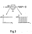
- Periodic switching or blocking of the current path occur e.g. by one for e.g. 11 V operating voltage designed glow plug, or for this voltage designed heating / control element, even at higher vehicle electrical system voltages operate.
- the periodic switching then generates a voltage which is in their effective value corresponds to the nominal operating voltage of the design.
- a circuit can be realized in such a way that a in the glow plug integrated sensor via the same supply connection of the heating or Control elements supplied or the measurement signal can be tapped.
- the following is a glow plug with insulation between the figures Heating element and motor mass, for example for use in ion current measurement, described; the known heating rods are suitable as heating rods, such as for example, those with a metal glow tube or glow tube (at least partially) conductive ceramics etc.
- the heating element (1) can be manufactured on existing standard equipment, this also applies to the pin (1.1), which later contacts the Establishes plug connection (4).
- Heating rod (1) can be pressed into the body (3) as before.
- the Insulating layer (2) can either be applied to the body (3) or to the heating element (1). This unit can be assembled completely automatically and checked for function.
- the insulating tube (15) serves as protection against contact and as a brake for the Molding compound (16) and is the next step between the heating element and body pressed in.
- the material is preferably a temperature-resistant plastic.
- the plug connection (4) is identical to the previous one in the connection area Executions. Accordingly, it has a connector pin on the connection side with or without Thread on.
- the plug connection (4) has a recess as a mounting platform (4.1) for the ceramic carrier (5), on which the electronic component (6) is pre-assembled. These two components together are on the Plug connection (4) in the area of the assembly platform (4.1) preferably applied by gluing.
- the busbars (11) and (12) can be encapsulated in a plastic housing (13) and as a complete. Component be pressed onto the plug connection (4).
- a twist protection (13.1) and the length stop (13.2) are provided so that the component can be installed in the correct position.
- connection on the electronic component - e.g. Supply voltage connection (7), connection to the glow tube (8) and earth connection (9) - be preferably with the bonding process with the respective contact parts Plug connection (4), busbar for glow tube (11) and busbar to body (12) connected.
- This unit is now, for example, with a resin (14) for stabilization shed.
- This completed component connector (4) with electronics etc. can be used as Bulk-compatible component can be delivered for final assembly.
- the plug connection (4) has a bore (4.2) in the axial direction, in which the pin (1.1) is pressed in by the heating element and the electrical contact to Manufactures inner pole (1.2) from the heating element (1).
- busbar (11) with the glow tube (1.3) and the Busbar (12) connected to the body (3).
- heating element (1) with body (3) and the plug connection (4) is in an injection mold is inserted and with extrusion coating (16) e.g. overmolded with PA 6.6.
- the circumferential groove (17) on the body (3) serves as an additional form fit safer introduction of force into the extrusion coating (16).
- Example 1 Ground contact in the glow mode of a glow plug with an electrically insulated heating element for ion current measurement:
- the glow plug according to the invention can now, for example with the aid of the integrated electronics, decide, based on the voltage present at the connection, whether glow operation is desired (voltage applied, for example less than 16 V) or whether an ion current should be measured (voltage applied, for example greater than 20 V).
- the electronics then short-circuit the glow tube with the glow plug body, for example, giving the ground connection necessary for operation.
- this connection is separated so that the part protruding into the combustion chamber of the engine is electrically insulated from it and can thus act as an electrode.
- the current flowing eg via the glow plug and the ions in the combustion chamber to ground, eg cylinder head
- Example 2 Operation of a heating element designed for a certain voltage at a higher voltage:
- Example 3 Alternating connection of a sensor signal and the operating voltage to the glow plug connection:
- the signal can be inserted into the glow plug integrated sensor are placed on the connection for operating the glow plug, thus avoiding a separate connection.
- the system is glow plug electronics 6-connector 4 modular design: On the one hand connector 4 with integrated electronics 6 for plugging together with the glow plug body 3 Heating rod 1 must be designed (two-part design). On the other hand, it can electronic component 6 with a push-on connector for connector 4 and one Push-on connection to glow plug body 3 with heating element 1 and through Plug together with connector 4 and body 3 to be connected to heating element 1 (three-part design).
- the inventive integration of the control electronics in the glow plug overcomes the disadvantages from the prior art listed at the beginning.
- the connector concept according to the invention permits automatic series production existing systems, whereby the individual components are capable of being handled in bulk, which is extremely advantageous for mass production and storage.
- the system according to the invention is less prone to errors, in particular contact resistances and voltage losses due to cable length being avoided.
- the standard dimensions of glow plugs are not exceeded, so that no special tools are required for glow plug assembly; the glow plugs according to the invention can also be operated on control units without ion current electronics.
Landscapes
- Engineering & Computer Science (AREA)
- Chemical & Material Sciences (AREA)
- Combustion & Propulsion (AREA)
- Mechanical Engineering (AREA)
- General Engineering & Computer Science (AREA)
- Ignition Installations For Internal Combustion Engines (AREA)
- Investigating, Analyzing Materials By Fluorescence Or Luminescence (AREA)
- Spark Plugs (AREA)
Applications Claiming Priority (2)
| Application Number | Priority Date | Filing Date | Title |
|---|---|---|---|
| DE19852485A DE19852485C2 (de) | 1998-11-13 | 1998-11-13 | Glühkerze und Steckanschluss für eine Glühkerze |
| DE19852485 | 1998-11-13 |
Publications (3)
| Publication Number | Publication Date |
|---|---|
| EP1001220A2 true EP1001220A2 (fr) | 2000-05-17 |
| EP1001220A3 EP1001220A3 (fr) | 2001-04-25 |
| EP1001220B1 EP1001220B1 (fr) | 2006-06-14 |
Family
ID=7887749
Family Applications (1)
| Application Number | Title | Priority Date | Filing Date |
|---|---|---|---|
| EP99121240A Expired - Lifetime EP1001220B1 (fr) | 1998-11-13 | 1999-10-25 | Bougie à tige incandescente |
Country Status (6)
| Country | Link |
|---|---|
| US (1) | US6150634A (fr) |
| EP (1) | EP1001220B1 (fr) |
| JP (1) | JP4368015B2 (fr) |
| AT (1) | ATE330182T1 (fr) |
| DE (2) | DE19852485C2 (fr) |
| ES (1) | ES2262285T3 (fr) |
Cited By (3)
| Publication number | Priority date | Publication date | Assignee | Title |
|---|---|---|---|---|
| WO2001020229A1 (fr) * | 1999-09-15 | 2001-03-22 | Robert Bosch Gmbh | Bougie crayon de prechauffage |
| US7122764B1 (en) | 2000-08-12 | 2006-10-17 | Robert Bosch Gmbh | Sheathed element glow plug |
| DE102013201048A1 (de) | 2013-01-23 | 2014-07-24 | Robert Bosch Gmbh | Glühstiftkerze |
Families Citing this family (13)
| Publication number | Priority date | Publication date | Assignee | Title |
|---|---|---|---|---|
| EP0834652B1 (fr) * | 1996-04-10 | 2004-10-13 | Denso Corporation | Bougie de prechauffage, son procede de fabrication, et detecteur de courant ionique |
| DE19842148C2 (de) * | 1998-09-15 | 2002-02-07 | Beru Ag | Ionenstrom-Meßglühkerze für Brennkraftmaschinen und Anordnung zum Glühen und/oder Ionenstrommessen mit einer derartigen Glühkerze |
| DE19849120C2 (de) * | 1998-10-23 | 2000-09-28 | Beru Ag | Glühkerze |
| DE19935025C2 (de) * | 1999-07-26 | 2001-05-23 | Beru Ag | Ionenstrommeßglühkerze und Steuergerät zu ihrer Ansteuerung |
| US6248980B1 (en) * | 1999-08-19 | 2001-06-19 | Delphi Technologies, Inc. | Ion sensor glow plug assembly |
| JP2001336468A (ja) * | 2000-03-22 | 2001-12-07 | Ngk Spark Plug Co Ltd | グロープラグ制御装置、グロープラグ、及びエンジンの燃焼室内のイオン検出方法 |
| DE10136596B4 (de) * | 2001-07-30 | 2005-09-15 | Beru Ag | Verfahren zur Verbindung eines stabförmigen Heizelements mit einem rohrförmigen Gehäuse einer Glühkerze und durch dieses Verfahren hergestellte Glühkerze |
| US20050098136A1 (en) * | 2003-11-10 | 2005-05-12 | Visteon Global Technologies, Inc. | Architecture to integrate ionization detection electronics into and near a diesel glow plug |
| SI21857A (sl) * | 2004-07-19 | 2006-02-28 | Cosylab, D.O.O. | Zarilna svecka z integriranim krmilnikom |
| JP4225273B2 (ja) * | 2004-11-25 | 2009-02-18 | 株式会社デンソー | グロープラグ |
| JP5720452B2 (ja) * | 2011-07-12 | 2015-05-20 | 株式会社デンソー | 発熱体通電制御装置 |
| JP6024524B2 (ja) * | 2013-03-07 | 2016-11-16 | 株式会社デンソー | コネクタ付き通電制御素子収容筐体並びに発熱体通電制御装置 |
| US9534575B2 (en) * | 2013-07-31 | 2017-01-03 | Borgwarner Ludwigsburg Gmbh | Method for igniting a fuel/air mixture, ignition system and glow plug |
Family Cites Families (8)
| Publication number | Priority date | Publication date | Assignee | Title |
|---|---|---|---|---|
| JPH07167433A (ja) * | 1993-12-13 | 1995-07-04 | Isuzu Ceramics Kenkyusho:Kk | 自己電流制御形グロープラグ |
| JPH07293417A (ja) * | 1994-04-22 | 1995-11-07 | Isuzu Ceramics Kenkyusho:Kk | 自己温度制御形グロープラグ |
| JP3605989B2 (ja) * | 1996-06-26 | 2004-12-22 | 株式会社デンソー | イオン電流検出装置 |
| JP3605990B2 (ja) * | 1996-04-10 | 2004-12-22 | 株式会社デンソー | イオン電流検出装置及びそれに用いられるグロープラグ |
| JP3814873B2 (ja) * | 1996-06-26 | 2006-08-30 | 株式会社デンソー | イオン電流検出装置 |
| JP3796846B2 (ja) * | 1996-09-12 | 2006-07-12 | 株式会社デンソー | グロープラグ |
| JP3605965B2 (ja) * | 1996-09-12 | 2004-12-22 | 株式会社デンソー | グロープラグ |
| DE19842148C2 (de) * | 1998-09-15 | 2002-02-07 | Beru Ag | Ionenstrom-Meßglühkerze für Brennkraftmaschinen und Anordnung zum Glühen und/oder Ionenstrommessen mit einer derartigen Glühkerze |
-
1998
- 1998-11-13 DE DE19852485A patent/DE19852485C2/de not_active Expired - Fee Related
-
1999
- 1999-10-25 DE DE59913553T patent/DE59913553D1/de not_active Expired - Lifetime
- 1999-10-25 ES ES99121240T patent/ES2262285T3/es not_active Expired - Lifetime
- 1999-10-25 AT AT99121240T patent/ATE330182T1/de not_active IP Right Cessation
- 1999-10-25 EP EP99121240A patent/EP1001220B1/fr not_active Expired - Lifetime
- 1999-11-12 JP JP32316199A patent/JP4368015B2/ja not_active Expired - Fee Related
- 1999-11-15 US US09/440,265 patent/US6150634A/en not_active Expired - Lifetime
Cited By (4)
| Publication number | Priority date | Publication date | Assignee | Title |
|---|---|---|---|---|
| WO2001020229A1 (fr) * | 1999-09-15 | 2001-03-22 | Robert Bosch Gmbh | Bougie crayon de prechauffage |
| US7122764B1 (en) | 2000-08-12 | 2006-10-17 | Robert Bosch Gmbh | Sheathed element glow plug |
| DE102013201048A1 (de) | 2013-01-23 | 2014-07-24 | Robert Bosch Gmbh | Glühstiftkerze |
| DE102013201048B4 (de) * | 2013-01-23 | 2015-08-13 | Robert Bosch Gmbh | Glühstiftkerze |
Also Published As
| Publication number | Publication date |
|---|---|
| JP4368015B2 (ja) | 2009-11-18 |
| DE59913553D1 (de) | 2006-07-27 |
| DE19852485C2 (de) | 2002-09-19 |
| ES2262285T3 (es) | 2006-11-16 |
| JP2000146180A (ja) | 2000-05-26 |
| EP1001220B1 (fr) | 2006-06-14 |
| EP1001220A3 (fr) | 2001-04-25 |
| DE19852485A1 (de) | 2000-05-25 |
| US6150634A (en) | 2000-11-21 |
| ATE330182T1 (de) | 2006-07-15 |
Similar Documents
| Publication | Publication Date | Title |
|---|---|---|
| DE19852485C2 (de) | Glühkerze und Steckanschluss für eine Glühkerze | |
| EP1238288B1 (fr) | Dispositif de capteur pour batterie | |
| EP1644749B1 (fr) | Dispositif de detection de reseau embarque et procede pour produire un dispositif de detection | |
| EP2946220B1 (fr) | Dispositif de mesure doté d'une résistance de mesure | |
| DE202008017318U1 (de) | Batteriemessklemme | |
| DE102004007851A1 (de) | Intelligente Anschlussvorrichtung | |
| DE19842148C2 (de) | Ionenstrom-Meßglühkerze für Brennkraftmaschinen und Anordnung zum Glühen und/oder Ionenstrommessen mit einer derartigen Glühkerze | |
| DE10007691B4 (de) | Verfahren und Vorrichtung zum Speichern und/oder Auslesen von Daten eines Kraftstoffzumesssystems | |
| DE102006019497B4 (de) | Sensorvorrichtung für eine Starterbatterie in einem Kraftfahrzeug | |
| EP1216384B1 (fr) | Bougie crayon de prechauffage | |
| WO2006119953A1 (fr) | Capteur de courant de batterie pour vehicule automobile | |
| DE102006029731B4 (de) | Batterieanschluss | |
| EP2831601B1 (fr) | Capteur de batterie électronique | |
| DE102009052353A1 (de) | Kontaktstecker | |
| EP4049898B1 (fr) | Ensemble de câbles, ainsi que procédé de conception d'un ensemble de câbles | |
| DE102021209142A1 (de) | Montagemodul zum Anschluss von mindestens einem Phasenausgang einer Invertervorrichtung sowie Inverteranordnung mit der Invertervorrichtung sowie dem Montagemodul | |
| DE102021132688A1 (de) | Elektronische Komponente mit Positionskodierung für ein Kraftfahrzeug | |
| DE4001538A1 (de) | Vorglueheinrichtung fuer dieselmotoren | |
| WO2022083925A1 (fr) | Connexion électrique, boîtier isolant associé, procédé et outil pour un tel procédé | |
| DE3611865C2 (fr) | ||
| DE60118431T2 (de) | Elektrischer pol für einen niederspannungs-unterbrecherschalter | |
| DE2363229A1 (de) | Anordnung zur einstellung von betriebsparametern an einer integrierten elektrischen schaltungseinheit | |
| AT413772B (de) | Kontrolleinrichtung für eine batterie | |
| DE102021212174A1 (de) | Elektrische Baugruppe mit Stromsensor | |
| WO2006048233A1 (fr) | Capteur de courant de batterie pour vehicule automobile |
Legal Events
| Date | Code | Title | Description |
|---|---|---|---|
| PUAI | Public reference made under article 153(3) epc to a published international application that has entered the european phase |
Free format text: ORIGINAL CODE: 0009012 |
|
| AK | Designated contracting states |
Kind code of ref document: A2 Designated state(s): AT BE CH CY DE DK ES FI FR GB GR IE IT LI LU MC NL PT SE |
|
| AX | Request for extension of the european patent |
Free format text: AL;LT;LV;MK;RO;SI |
|
| PUAL | Search report despatched |
Free format text: ORIGINAL CODE: 0009013 |
|
| AK | Designated contracting states |
Kind code of ref document: A3 Designated state(s): AT BE CH CY DE DK ES FI FR GB GR IE IT LI LU MC NL PT SE |
|
| AX | Request for extension of the european patent |
Free format text: AL;LT;LV;MK;RO;SI |
|
| 17P | Request for examination filed |
Effective date: 20010702 |
|
| AKX | Designation fees paid |
Free format text: AT DE ES FR GB IT NL |
|
| RBV | Designated contracting states (corrected) |
Designated state(s): AT BE CH CY DE DK ES FI FR GB GR IE IT LI LU MC NL PT SE |
|
| 17Q | First examination report despatched |
Effective date: 20040109 |
|
| GRAP | Despatch of communication of intention to grant a patent |
Free format text: ORIGINAL CODE: EPIDOSNIGR1 |
|
| GRAS | Grant fee paid |
Free format text: ORIGINAL CODE: EPIDOSNIGR3 |
|
| RBV | Designated contracting states (corrected) |
Designated state(s): AT DE ES FR GB IT NL |
|
| RBV | Designated contracting states (corrected) |
Designated state(s): AT BE CH CY DE DK ES FI FR GB GR IE IT LI LU MC NL PT SE |
|
| GRAA | (expected) grant |
Free format text: ORIGINAL CODE: 0009210 |
|
| AK | Designated contracting states |
Kind code of ref document: B1 Designated state(s): AT BE CH CY DE DK ES FI FR GB GR IE IT LI LU MC NL PT SE |
|
| PG25 | Lapsed in a contracting state [announced via postgrant information from national office to epo] |
Ref country code: NL Free format text: LAPSE BECAUSE OF FAILURE TO SUBMIT A TRANSLATION OF THE DESCRIPTION OR TO PAY THE FEE WITHIN THE PRESCRIBED TIME-LIMIT Effective date: 20060614 Ref country code: IT Free format text: LAPSE BECAUSE OF FAILURE TO SUBMIT A TRANSLATION OF THE DESCRIPTION OR TO PAY THE FEE WITHIN THE PRESCRIBED TIME-LIMIT;WARNING: LAPSES OF ITALIAN PATENTS WITH EFFECTIVE DATE BEFORE 2007 MAY HAVE OCCURRED AT ANY TIME BEFORE 2007. THE CORRECT EFFECTIVE DATE MAY BE DIFFERENT FROM THE ONE RECORDED. Effective date: 20060614 Ref country code: IE Free format text: LAPSE BECAUSE OF FAILURE TO SUBMIT A TRANSLATION OF THE DESCRIPTION OR TO PAY THE FEE WITHIN THE PRESCRIBED TIME-LIMIT Effective date: 20060614 Ref country code: FI Free format text: LAPSE BECAUSE OF FAILURE TO SUBMIT A TRANSLATION OF THE DESCRIPTION OR TO PAY THE FEE WITHIN THE PRESCRIBED TIME-LIMIT Effective date: 20060614 |
|
| REG | Reference to a national code |
Ref country code: GB Ref legal event code: FG4D Free format text: NOT ENGLISH |
|
| REG | Reference to a national code |
Ref country code: CH Ref legal event code: EP |
|
| REG | Reference to a national code |
Ref country code: IE Ref legal event code: FG4D Free format text: LANGUAGE OF EP DOCUMENT: GERMAN |
|
| REF | Corresponds to: |
Ref document number: 59913553 Country of ref document: DE Date of ref document: 20060727 Kind code of ref document: P |
|
| GBT | Gb: translation of ep patent filed (gb section 77(6)(a)/1977) |
Effective date: 20060724 |
|
| PG25 | Lapsed in a contracting state [announced via postgrant information from national office to epo] |
Ref country code: DK Free format text: LAPSE BECAUSE OF FAILURE TO SUBMIT A TRANSLATION OF THE DESCRIPTION OR TO PAY THE FEE WITHIN THE PRESCRIBED TIME-LIMIT Effective date: 20060914 |
|
| REG | Reference to a national code |
Ref country code: SE Ref legal event code: TRGR |
|
| PG25 | Lapsed in a contracting state [announced via postgrant information from national office to epo] |
Ref country code: MC Free format text: LAPSE BECAUSE OF NON-PAYMENT OF DUE FEES Effective date: 20061031 Ref country code: LI Free format text: LAPSE BECAUSE OF NON-PAYMENT OF DUE FEES Effective date: 20061031 Ref country code: CH Free format text: LAPSE BECAUSE OF NON-PAYMENT OF DUE FEES Effective date: 20061031 |
|
| PG25 | Lapsed in a contracting state [announced via postgrant information from national office to epo] |
Ref country code: PT Free format text: LAPSE BECAUSE OF FAILURE TO SUBMIT A TRANSLATION OF THE DESCRIPTION OR TO PAY THE FEE WITHIN THE PRESCRIBED TIME-LIMIT Effective date: 20061114 |
|
| REG | Reference to a national code |
Ref country code: ES Ref legal event code: FG2A Ref document number: 2262285 Country of ref document: ES Kind code of ref document: T3 |
|
| NLV1 | Nl: lapsed or annulled due to failure to fulfill the requirements of art. 29p and 29m of the patents act | ||
| ET | Fr: translation filed | ||
| PLBE | No opposition filed within time limit |
Free format text: ORIGINAL CODE: 0009261 |
|
| STAA | Information on the status of an ep patent application or granted ep patent |
Free format text: STATUS: NO OPPOSITION FILED WITHIN TIME LIMIT |
|
| 26N | No opposition filed |
Effective date: 20070315 |
|
| REG | Reference to a national code |
Ref country code: CH Ref legal event code: PL |
|
| BERE | Be: lapsed |
Owner name: BERU A.G. Effective date: 20061031 |
|
| PG25 | Lapsed in a contracting state [announced via postgrant information from national office to epo] |
Ref country code: GR Free format text: LAPSE BECAUSE OF FAILURE TO SUBMIT A TRANSLATION OF THE DESCRIPTION OR TO PAY THE FEE WITHIN THE PRESCRIBED TIME-LIMIT Effective date: 20060915 |
|
| PG25 | Lapsed in a contracting state [announced via postgrant information from national office to epo] |
Ref country code: LU Free format text: LAPSE BECAUSE OF NON-PAYMENT OF DUE FEES Effective date: 20061025 |
|
| PG25 | Lapsed in a contracting state [announced via postgrant information from national office to epo] |
Ref country code: CY Free format text: LAPSE BECAUSE OF FAILURE TO SUBMIT A TRANSLATION OF THE DESCRIPTION OR TO PAY THE FEE WITHIN THE PRESCRIBED TIME-LIMIT Effective date: 20060614 |
|
| PGFP | Annual fee paid to national office [announced via postgrant information from national office to epo] |
Ref country code: ES Payment date: 20081030 Year of fee payment: 10 Ref country code: AT Payment date: 20081013 Year of fee payment: 10 |
|
| PGFP | Annual fee paid to national office [announced via postgrant information from national office to epo] |
Ref country code: SE Payment date: 20081015 Year of fee payment: 10 Ref country code: IT Payment date: 20081028 Year of fee payment: 10 |
|
| PGFP | Annual fee paid to national office [announced via postgrant information from national office to epo] |
Ref country code: FR Payment date: 20081014 Year of fee payment: 10 |
|
| PGFP | Annual fee paid to national office [announced via postgrant information from national office to epo] |
Ref country code: GB Payment date: 20081014 Year of fee payment: 10 |
|
| PG25 | Lapsed in a contracting state [announced via postgrant information from national office to epo] |
Ref country code: BE Free format text: LAPSE BECAUSE OF FAILURE TO SUBMIT A TRANSLATION OF THE DESCRIPTION OR TO PAY THE FEE WITHIN THE PRESCRIBED TIME-LIMIT Effective date: 20061031 |
|
| EUG | Se: european patent has lapsed | ||
| REG | Reference to a national code |
Ref country code: FR Ref legal event code: ST Effective date: 20100630 |
|
| PG25 | Lapsed in a contracting state [announced via postgrant information from national office to epo] |
Ref country code: FR Free format text: LAPSE BECAUSE OF NON-PAYMENT OF DUE FEES Effective date: 20091102 |
|
| PG25 | Lapsed in a contracting state [announced via postgrant information from national office to epo] |
Ref country code: AT Free format text: LAPSE BECAUSE OF NON-PAYMENT OF DUE FEES Effective date: 20091025 |
|
| PG25 | Lapsed in a contracting state [announced via postgrant information from national office to epo] |
Ref country code: GB Free format text: LAPSE BECAUSE OF NON-PAYMENT OF DUE FEES Effective date: 20091025 |
|
| REG | Reference to a national code |
Ref country code: ES Ref legal event code: FD2A Effective date: 20110330 |
|
| PG25 | Lapsed in a contracting state [announced via postgrant information from national office to epo] |
Ref country code: IT Free format text: LAPSE BECAUSE OF NON-PAYMENT OF DUE FEES Effective date: 20091025 |
|
| PG25 | Lapsed in a contracting state [announced via postgrant information from national office to epo] |
Ref country code: SE Free format text: LAPSE BECAUSE OF NON-PAYMENT OF DUE FEES Effective date: 20091026 |
|
| REG | Reference to a national code |
Ref country code: DE Ref legal event code: R081 Ref document number: 59913553 Country of ref document: DE Owner name: BORGWARNER BERU SYSTEMS GMBH, DE Free format text: FORMER OWNER: BERU AG, 71636 LUDWIGSBURG, DE Effective date: 20110331 |
|
| PG25 | Lapsed in a contracting state [announced via postgrant information from national office to epo] |
Ref country code: ES Free format text: LAPSE BECAUSE OF NON-PAYMENT OF DUE FEES Effective date: 20110317 |
|
| PG25 | Lapsed in a contracting state [announced via postgrant information from national office to epo] |
Ref country code: ES Free format text: LAPSE BECAUSE OF NON-PAYMENT OF DUE FEES Effective date: 20091026 |
|
| PGFP | Annual fee paid to national office [announced via postgrant information from national office to epo] |
Ref country code: DE Payment date: 20121012 Year of fee payment: 14 |
|
| REG | Reference to a national code |
Ref country code: DE Ref legal event code: R119 Ref document number: 59913553 Country of ref document: DE Effective date: 20140501 |
|
| PG25 | Lapsed in a contracting state [announced via postgrant information from national office to epo] |
Ref country code: DE Free format text: LAPSE BECAUSE OF NON-PAYMENT OF DUE FEES Effective date: 20140501 |