EP1001259A2 - Capteur de point de rosée - Google Patents
Capteur de point de rosée Download PDFInfo
- Publication number
- EP1001259A2 EP1001259A2 EP99309042A EP99309042A EP1001259A2 EP 1001259 A2 EP1001259 A2 EP 1001259A2 EP 99309042 A EP99309042 A EP 99309042A EP 99309042 A EP99309042 A EP 99309042A EP 1001259 A2 EP1001259 A2 EP 1001259A2
- Authority
- EP
- European Patent Office
- Prior art keywords
- temperature
- quartz crystal
- crystal resonator
- dewpoint
- frequency
- Prior art date
- Legal status (The legal status is an assumption and is not a legal conclusion. Google has not performed a legal analysis and makes no representation as to the accuracy of the status listed.)
- Withdrawn
Links
Images


Classifications
-
- G—PHYSICS
- G01—MEASURING; TESTING
- G01N—INVESTIGATING OR ANALYSING MATERIALS BY DETERMINING THEIR CHEMICAL OR PHYSICAL PROPERTIES
- G01N29/00—Investigating or analysing materials by the use of ultrasonic, sonic or infrasonic waves; Visualisation of the interior of objects by transmitting ultrasonic or sonic waves through the object
- G01N29/02—Analysing fluids
- G01N29/036—Analysing fluids by measuring frequency or resonance of acoustic waves
-
- G—PHYSICS
- G01—MEASURING; TESTING
- G01N—INVESTIGATING OR ANALYSING MATERIALS BY DETERMINING THEIR CHEMICAL OR PHYSICAL PROPERTIES
- G01N25/00—Investigating or analyzing materials by the use of thermal means
- G01N25/56—Investigating or analyzing materials by the use of thermal means by investigating moisture content
- G01N25/66—Investigating or analyzing materials by the use of thermal means by investigating moisture content by investigating dew-point
- G01N25/68—Investigating or analyzing materials by the use of thermal means by investigating moisture content by investigating dew-point by varying the temperature of a condensing surface
-
- G—PHYSICS
- G01—MEASURING; TESTING
- G01N—INVESTIGATING OR ANALYSING MATERIALS BY DETERMINING THEIR CHEMICAL OR PHYSICAL PROPERTIES
- G01N2291/00—Indexing codes associated with group G01N29/00
- G01N2291/02—Indexing codes associated with the analysed material
- G01N2291/025—Change of phase or condition
- G01N2291/0256—Adsorption, desorption, surface mass change, e.g. on biosensors
Definitions
- This invention relates generally to dewpoint sensors and more specifically to non-optical dewpoint sensors.
- Industrial power generation gas turbine engines include a compressor for compressing air that is mixed with fuel and ignited in a combustor for generating combustion gases.
- the combustion gases flow to a turbine that extracts energy for driving a shaft to power the compressor and produces output power for powering an electrical generator, for example.
- the turbine is typically operated for extended periods of time at a relatively high base load for powering the generator to produce electrical power to a utility grid, for example. Exhaust emissions from the combustion gases are therefore a concern and are subjected to mandated limits.
- Low emission combustion systems are designed to produce low emissions and high combustion efficiency while burning natural gas fuel that is assumed to be free of liquid or solid contaminants.
- pipeline gas is at times contaminated with condensed liquid hydrocarbons (to varying degrees) as well as other solid particulate contaminants. It is highly desirable to minimize the effects of these contaminants on gas turbine combustor performance, either by their removal or by robust combustor design.
- the presence of varying amounts of liquid hydrocarbons in the fuel source has become an increasing operational issue.
- the quality of natural gas supplied to gas turbines is an important variable in turbine performance.
- the principle component of natural gas is methane, which typically accounts for over 90% of the mass.
- Other components in natural gas may include heavier hydrocarbons, oils and water.
- the chemical composition of the gas is particularly important because of the potential for ignition to occur within the mixing zone.
- the effect of heavier hydrocarbons and oils in the gas stream is to lower the autoignition temperature of the mixture. Natural gas with high concentrations of these species is more likely to ignite in the mixing zone of the combustors than in an intended flame holder region.
- Certain optical dewpoint meters can determine the dewpoint of either water or hydrocarbons in natural gas.
- One instrument uses two chilled surfaces, each with different surface properties to distinguish between the water and hydrocarbon dewpoint.
- a second unit uses a specially shaped mirror that is designed to detect hydrocarbon dewpoint. To measure water dewpoint, this unit employs a second ceramic sensor that measures impedance. Both instruments are rendered inoperable when the optical surface is contaminated by certain compounds such as glycols, lubricating oils and hydrocarbons.
- Non-optical instruments exist for the measurement of water dewpoint.
- One unit includes humidity sensors based on electrical resistivity changes of a hygroscopic polymer coating on a ceramic substrate and sensors based on the electrical capacitance changes of a thin layer of polymer between two metal electrodes. While these polymer-based sensors do not rely on optically clean surfaces, they are only useful to measure water dewpoints, and could not be used to measure hydrocarbon dewpoints.
- Quartz crystal resonators have been used to measure water humidity and dewpoint in air and other gases.
- Canadian patent 1,301,477 (1992) by Claude Porltier et al. describes a QCR system to measure humidity of gases.
- Teruko Inamatsu and Chiharu Takahashi (1985) describe a dewpoint hygrometer based on QCR for humidity measurements.
- a dewpoint sensor which comprises a pressure vessel having
- a dewpoint sensor comprises a pressure vessel having an entry port, an exit port, and a temperature controlled plate.
- a quartz crystal resonator is housed within the pressure vessel and is disposed in intimate contact with the temperature controlled plate.
- a temperature sensor is disposed to generate signals representative of the quartz crystal resonator temperature.
- Circuitry is coupled to the quartz crystal resonator and the temperature sensor, which circuitry is configured to control the temperature of the quartz crystal resonator, to measure the frequency of the quartz crystal resonator and to monitor the frequency of the quartz crystal resonator when exposed to a flow between the entry port and the exit port so as to calculate a dewpoint temperature value of the flow.
- a pipeline 50 comprising an inlet 52 and an outlet 54 provides fluid communication between a fuel source 56 and a fuel consumer 10, for example, a power turbine, as shown in Fig. 1.
- a shut off valve 58 is disposed within pipeline 50, which valve 58 is movable between a fully open position and a fully closed position to allow or prevent fuel flow, respectively, from fuel source 56 to power turbine 10.
- a dewpoint sensor 100 is coupled to pipeline 50.
- a conduit 102 or the like provides flow communication between pipeline 50 and dewpoint sensor 100.
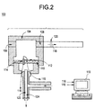
- Dewpoint sensor 100 comprises a pressure vessel 104 having an entry port 106, an exit port 108 and a temperature controlled plate 110, as best shown in FIG. 2.
- a quartz crystal resonator 112 is housed within pressure vessel 104 and is disposed in intimate contact with temperature controlled plate 110.
- a temperature sensor 114 is disposed to generate signals representative of the temperature of quartz crystal resonator 112.
- Temperature sensor 114 typically comprises a thermistor, a thermocouple or the like.
- Circuitry 116 is coupled to quartz crystal resonator 112 and temperature sensor 114. Circuitry 116 is configured to control the of quartz crystal resonator 112, and to monitor the temperature signals and the frequency of quartz crystal resonator 112 when exposed to a fuel flow 118 between entry port 106 and exit port 108 so as to calculate a dewpoint value of fuel flow 118 in a manner discussed in greater detail below.
- circuitry 116 includes a power input and a processor for monitoring the signals and generating an output signal.
- circuitry 116 comprises a computer 119 for processing signals and generating a dewpoint report and display.
- fuel flow 118 comprises a natural gas, for example, propane, hexane, heptane, gas derived from coal, methane or the like. As discussed above, fuel flow 118 flows from fuel source 56 to power turbine 10. A slipstream of fuel flow 118 is directed from pipeline 50 through conduit 102 into entry port 106 of pressure vessel 104.
- the instant invention is shown connected to a pipeline 50 for turbine engine 10, this device could also be applied to monitor the quality of process gases, not necessarily intended for combustion, in which the composition can be determined by measurement of dewpoint.
- gas mixtures are water ammonia mixtures used in refrigeration cycles and feed stocks for the synthesis of polymer materials.
- the instant invention can be utilized for: monitoring gas quality at the exit of a cryogenic gas processing system; monitoring gas quality at the custody transfer point between a gas producer and a gas transmission company; monitoring gas quality at the custody transfer point between a gas transmission company and a local distribution company; monitoring gas quality at a compressor station used to compress gas for natural gas powered vehicles, or the like.
- a back pressure valve 120 is typically disposed at exit port 108 to control the flow through pressure vessel 104.
- back pressure valve 120 maintains the pressure of pressure vessel 104 substantially equal to the pressure of pipeline 50 (FIG. 1).
- Temperature controlled plate 110 is typically disposed in thermal intimacy with a cooling device 122 or a heating device 124.
- Cooling device 122 may comprise a vortex tube cooler, a Peltier device or the like.
- a vortex tube cooler uses compressed air as an energy source. As the air is expanded in the vortex tube, the air is separated into two streams, one hotter and one cooler than the supply air. By generating a hotter air stream it is possible to cool the cooler stream much more than can be achieved by expanding the supply air in a conventional manner.
- a Peltier device employs the thermal electric properties of dissimilar materials, usually metals or semiconductors configured as electrodes in an electric circuit. By applying an external voltage to the Peltier device one electrode becomes hotter and one will become cooler than the ambient conditions.
- Heating device 124 may comprise an electric heater, a high temperature stream of a vortex cooler, or a Peltier device operated with opposite voltage polarity from the cooling mode, or the like.
- Temperature controlled plate 110 is typically made of material having a high thermal conductivity value like copper or the like. Control plate 110 may be plated with a corrosion inhibiting metal, such as gold, to prevent reaction with components of natural gas.
- Temperature sensor 114 generates signals that correspond to the temperature of the crystal. By monitoring temperature and frequency change as the crystal is cooled, the dewpoint can be determined.
- dewpoint sensor 100 measures the dewpoint whether the condensate is water or an organic material.
- a method for determining gas quality using dewpoint sensor 100 is depicted in flow chart 500 of FIG 3.
- a control structure is inputted into circuitry 116, for example, by programming into memory of an application specific integrated circuit (ASIC) or is embedded in the form of algorithms in one or more computers 119 such as a work station.
- ASIC application specific integrated circuit
- computers 119 such as a work station.
- Other types of computers can be used, however, such as a minicomputer, a microcomputer, or a supercomputer, for example.
- the programming or algorithm performed may be programmed in C, C++, JAVA, Basic, MATLAB, FORTRAN, or other programming languages.
- pressure vessel 104 (FIG 2) is purged with a slipstream of gas flow 118.
- circuitry 116 (FIG 2) generates a signal to cooling device 122 to begin cooling QCR 112.
- circuitry 116 (FIG 2) measures the frequency and temperature of QCR 112.
- circuitry 116 monitors the frequency of QCR 112 to determine if the change in frequency ( ⁇ F) over a predetermined period of time is greater than a set point change in frequency ( ⁇ Fs). In this embodiment, ⁇ F is selected to coincide with the dewpoint temperature of the flow, If the value of ⁇ F does not exceed the value of ⁇ Fs, the control sequence returns to block 504 (FIG 3) and continues cooling QCR 112 (FIG 2).
- the temperature of QCR 112 has substantially reached the dewpoint temperature of the gas flow and the dewpoint temperature is known.
- the dewpoint temperature is reported, stored in a data base, or displayed to a system user.
- the cooling is stopped. Heat is then applied to the crystal at block 516.
- circuitry 116 monitors the temperature of the crystal to determine if the crystal has warmed up to a setpoint temperature. If the temperature of the crystal does not exceed the setpoint temperature, the control sequence returns to block 516 (FIG 3) and more heat is applied to the crystal.
- control sequence advances to block 520.
- circuitry 112 generates a signal to heating device 124 (FIG 2) to stop heating.
- the control sequence begins a new cycle and returns to block 502.
- circuitry 116 may initiate a system control, for example, limit turbine engine 10 to low load operation. Additionally, if the dewpoint temperature rises above a setpoint temperature, circuitry 116 may initiate an algorithm to look at combustion system anomalies, or, for example, sound an alarm or otherwise alert a system user.
- the dewpoint of the flow may be determined without cooling the crystal to the dewpoint temperature. This prevents accumulation of liquids and particulates which may foul the crystal over time.
- the parameter x in Eq. 1 is ratio of the partial pressure to the vapor pressure of the gas.
- the partial pressure is the mole fraction, y, times the total pressure P.
- a and B empirical constants
- T is the absolute temperature.
- Equations 1, 2 and 4 can be used to relate the measured thickness, t, to the measured temperature, T.
- the five constants A, B, c, D and E can be adjusted to minimize the error between the measured data and the resulting model curve.
- This system will cool the crystal at a sufficiently slow rate to ensure equilibrium conditions and calculate the best-fit parameters in the B.E.T. model that are used to determining the dewpoint.
- a curve fitting method of determining gas quality using dewpoint sensor 100 is depicted in flow chart 600 of FIG 4.
- pressure vessel 104 is purged with a slipstream of gas flow 118 (FIG 2).
- circuitry 116 (FIG 2) generates a signal to cooling device 122 to begin cooling QCR 112.
- circuitry 116 (FIG 2) measures the frequency and temperature of QCR 112. The frequency and temperature measurements are then stored as a function of time at block 608 (FIG 4).
- circuitry 116 monitors the frequency and temperature of QCR 112 to determine if the change in frequency ⁇ F over a predetermined period of time is greater than a set point change in frequency ⁇ Fs.
- ⁇ Fs is selected to provide sufficient data to apply the curve fitting algorithm while maintaining the crystal above the dewpoint temperature.
- ⁇ Fs is in the range between about 1000 Hz to about 10,000 Hz and QCR 112 uses a 6 MHz crystal. If the value of ⁇ F does not exceed the value of ⁇ Fs, the control sequence returns to block 604 (FIG 4) and continues cooling QCR 112 (FIG 2).
- the temperature of QCR 112 is approaching the dewpoint of the gas flow.
- the cooling is stopped. Heat is then applied to the crystal at block 614.
- the curve-fitting algorithm is applied to determine the dewpoint as discussed above. Because the dewpoint is calculated prior to cooling the crystal to the dewpoint temperature, the accumulation of liquids and particulates on the crystal is prevented.
- the calculated dewpoint temperature is reported, stored in a database or displayed to a system user.
- circuitry 116 (FIG 2) monitors the temperature of the crystal to determine if the crystal has warmed up to a setpoint temperature. If the temperature of the crystal does not exceed the setpoint temperature, the control sequence returns to block 614 (FIG 4) and more heat is applied to the crystal.
- control sequence advances to block 622.
- circuitry 116 (FIG 2) generates a signal to heating device 124 to stop heating.
- control sequence begins a new cycle and returns to block 602.
- circuitry 116 may, for example, limit turbine engine 10 to low load operation. Additionally, if the dewpoint temperature rises above a setpoint temperature, circuitry 116 may initiate an -algorithm to look at combustion system anomalies.
- the dewpoint temperature must be a predetermined value below the pipeline gas temperature for the fuel to meet the specification.
- the turbine control unit would calculate the gas superheat temperature based on measurements of pipeline gas temperature and gas dewpoint temperature.
- the control system will take action if the superheat criteria is not met.
- the action to be taken is subject to the accuracy in the measurement and the risk posed by bad gas.
- One approach is to indicate poor gas quality (Superheat ⁇ 50°F) as an alarm and not as a trip.
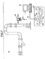
- a pipeline 50 comprising an inlet 52 and an outlet 54 provides fluid communication between a fuel source 56 and power turbine 10, is shown in Fig. 5.
- a shut-off valve 58 is disposed within pipeline 50, which valve 58 is movable between a fully open position and a fully closed position to allow or prevent fuel flow, respectively, from fuel source 56 to power turbine 10.
- an inline dewpoint sensor 200 is disposed within a sidewall 202 of pipeline 50 for direct readings, as shown in FIG. 5.
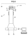
- Inline dewpoint sensor 200 comprises a housing 204 that is removably disposed within a sidewall 202 of pipeline 50. Housing 204 is disposed, with the appropriate seals (not shown) to prevent leakage of flow from pipeline 50.
- Housing 204 comprises an entry port 206 and an exit port 208, as best shown in FIG. 6.
- a thermal connector 210 is disposed so as to extend within pipeline 50 through entry port 208.
- a quartz crystal resonator 212 is housed within housing 204 and is disposed in intimate contact with thermal connector 210.
- a temperature sensor 214 is disposed to generate signals representative of the temperature of quartz crystal resonator 212.
- Circuitry 216 is coupled to quartz crystal resonator 212 and temperature sensor 214.
- Circuitry 216 is configured to control the temperature of quartz crystal resonator 212, to measure the frequency of quartz crystal resonator 212, and to monitor the frequency of quartz crystal resonator 212 when exposed to a flow 218 between entry port 206 and exit port 208 so as to calculate a dewpoint value of fuel flow 218.
- circuitry 216 includes a power input and a processor for monitoring the signal and generating an output signal. In another embodiment, circuitry 216 comprises a computer 219 for processing signals and generating a dewpoint report and display.
- Cooling of QCR 212 is typically by means of an internal cooler 220, for example, a thermoelectric cooler (TEC) with a heat sink or an external cooler, for example, a vortex tube or TEC.
- TEC thermoelectric cooler
- the connection of housing 204 to pipeline 50 can be via a pipe thread connection or other fastening means.
- a remote dewpoint sensor 300 is shown in Fig. 7. This embodiment is similar in all respects to the dewpoint sensor of FIG. 1 or FIG. 6, except that circuitry is electronically coupled to at least one remote unit 302 for transmitting signals from dewpoint sensor 300.
- a remote station 304 provides a communication base for interaction with a respective remote unit 302.
- Remote station 304 typically comprises a central interface 306, a radio frequency (RF) front-end 308, an antenna 310 and user interface related peripheral devices including a user interface 312, a display 314, data storage 316 and a printer 318 for enabling a user to input relevant information into central interface 306.
- Peripheral devices as defined in this application include any device for storing dewpoint and of measurement or analysis information and intelligibly communicating the same to a system user, and include such devices as printers, hard disk drives, floppy disk drives, cathode ray tubes (CRTs) and keyboards. While only one set of respective peripheral devices are shown for a respective central interface 306, any number of peripheral devices may be utilized and are within the scope of the instant invention.
- Communication between remote station 304 and a respective remote unit 302 is by way of a communication system 320, such as a "geo-synchronous" "L-band” satellite system, a “Little Leo” satellite system, a two-way paging system, a modem connection or any communication system capable of two-way communication between remote station 304 and a respective remote unit 302.
- a communication system 320 such as a "geo-synchronous" "L-band” satellite system, a “Little Leo” satellite system, a two-way paging system, a modem connection or any communication system capable of two-way communication between remote station 304 and a respective remote unit 302.
Landscapes
- Physics & Mathematics (AREA)
- Biochemistry (AREA)
- Health & Medical Sciences (AREA)
- Life Sciences & Earth Sciences (AREA)
- Chemical & Material Sciences (AREA)
- Analytical Chemistry (AREA)
- General Health & Medical Sciences (AREA)
- General Physics & Mathematics (AREA)
- Immunology (AREA)
- Pathology (AREA)
- Acoustics & Sound (AREA)
- Investigating Or Analyzing Materials Using Thermal Means (AREA)
- Measuring Fluid Pressure (AREA)
Applications Claiming Priority (2)
| Application Number | Priority Date | Filing Date | Title |
|---|---|---|---|
| US09/191,248 US6073479A (en) | 1998-11-13 | 1998-11-13 | Dewpoint sensor |
| US191248 | 1998-11-13 |
Publications (2)
| Publication Number | Publication Date |
|---|---|
| EP1001259A2 true EP1001259A2 (fr) | 2000-05-17 |
| EP1001259A3 EP1001259A3 (fr) | 2003-04-16 |
Family
ID=22704715
Family Applications (1)
| Application Number | Title | Priority Date | Filing Date |
|---|---|---|---|
| EP99309042A Withdrawn EP1001259A3 (fr) | 1998-11-13 | 1999-11-12 | Capteur de point de rosée |
Country Status (3)
| Country | Link |
|---|---|
| US (2) | US6073479A (fr) |
| EP (1) | EP1001259A3 (fr) |
| JP (1) | JP2000283938A (fr) |
Families Citing this family (37)
| Publication number | Priority date | Publication date | Assignee | Title |
|---|---|---|---|---|
| US6494079B1 (en) | 2001-03-07 | 2002-12-17 | Symyx Technologies, Inc. | Method and apparatus for characterizing materials by using a mechanical resonator |
| GB9814862D0 (en) * | 1998-07-10 | 1998-09-09 | South Bank Univ Entpr Ltd | Method and equipment for measuring vapour flux from surfaces |
| US6488405B1 (en) * | 2000-03-08 | 2002-12-03 | Advanced Micro Devices, Inc. | Flip chip defect analysis using liquid crystal |
| US6468682B1 (en) | 2000-05-17 | 2002-10-22 | Avista Laboratories, Inc. | Ion exchange membrane fuel cell |
| US6442492B1 (en) * | 2000-06-22 | 2002-08-27 | Uop Llc | Controlling moisture content of vapor in calcination or oxidation zones |
| US6806842B2 (en) * | 2000-07-18 | 2004-10-19 | Marconi Intellectual Property (Us) Inc. | Wireless communication device and method for discs |
| US7098850B2 (en) * | 2000-07-18 | 2006-08-29 | King Patrick F | Grounded antenna for a wireless communication device and method |
| US6483473B1 (en) * | 2000-07-18 | 2002-11-19 | Marconi Communications Inc. | Wireless communication device and method |
| JP4610097B2 (ja) * | 2001-02-08 | 2011-01-12 | 日産自動車株式会社 | 燃料改質システム |
| US20020168772A1 (en) * | 2001-05-11 | 2002-11-14 | Lloyd Greg A. | Method of detecting poisoning of a MOS gas sensor |
| WO2002099414A1 (fr) | 2001-06-06 | 2002-12-12 | Symyx Technologies, Inc. | Detecteurs d'ecoulement equipes d'oscillateurs mecaniques et utilisation de ces detecteurs dans des systemes de caracterisation d'un ecoulement |
| US6839613B2 (en) | 2001-07-17 | 2005-01-04 | General Electric Company | Remote tuning for gas turbines |
| US6532792B2 (en) | 2001-07-26 | 2003-03-18 | Avista Laboratories, Inc. | Method of compensating a MOS gas sensor, method of manufacturing a MOS gas sensor, MOS gas sensor, and fuel cell system |
| DE60322528D1 (de) * | 2002-04-24 | 2008-09-11 | Mineral Lassen Llc | Herstellungsverfahren für eine drahtlose kommunikationseinrichtung und herstellungsvorrichtung |
| JP2005524134A (ja) * | 2002-04-25 | 2005-08-11 | グラクソ グループ リミテッド | 環境条件を検知するための磁気音響センサーシステムおよびそれに関連する方法 |
| US20040076216A1 (en) * | 2002-10-18 | 2004-04-22 | Chamberlain Craig A. | Thermographic system and method for detecting imperfections within a bond |
| AU2003282936A1 (en) | 2002-10-18 | 2004-05-04 | Symyx Technologies, Inc. | Environmental control system fluid sensing system and method comprising a sesnsor with a mechanical resonator |
| US7043969B2 (en) | 2002-10-18 | 2006-05-16 | Symyx Technologies, Inc. | Machine fluid sensor and method |
| US7721590B2 (en) | 2003-03-21 | 2010-05-25 | MEAS France | Resonator sensor assembly |
| US7210332B2 (en) | 2003-03-21 | 2007-05-01 | Symyx Technologies, Inc. | Mechanical resonator |
| ATE546720T1 (de) * | 2003-03-21 | 2012-03-15 | MEAS France | Resonator-sensor-einheit |
| NL1023791C2 (nl) * | 2003-07-01 | 2005-01-04 | Lely Entpr Ag | Melkinstallatie. |
| GB0418555D0 (en) * | 2004-08-19 | 2004-09-22 | Michell Instr Ltd | Apparatus for measuring dew point of a gas stream |
| US7363911B2 (en) * | 2005-11-03 | 2008-04-29 | Ford Global Technologies, Llc | Humidity-based combustion control in a multiple combustion mode engine |
| KR100926461B1 (ko) * | 2007-12-14 | 2009-11-13 | 한국표준과학연구원 | 수정미소저울 노점센서를 이용한 저온에서의 상점과 이슬점구별 측정 방법 |
| US8474265B2 (en) * | 2009-07-29 | 2013-07-02 | General Electric Company | Fuel nozzle for a turbine combustor, and methods of forming same |
| US9388686B2 (en) | 2010-01-13 | 2016-07-12 | Halliburton Energy Services, Inc. | Maximizing hydrocarbon production while controlling phase behavior or precipitation of reservoir impairing liquids or solids |
| JP5447975B2 (ja) * | 2010-06-29 | 2014-03-19 | 住友電装株式会社 | ガス分配ユニット |
| CA2722722C (fr) * | 2010-11-24 | 2017-08-22 | Transcanada Pipelines Limited | Detection de composant polaire |
| JPWO2013008753A1 (ja) * | 2011-07-13 | 2015-02-23 | ステラグリーン株式会社 | 湿度センサ |
| US8568021B2 (en) * | 2011-09-29 | 2013-10-29 | Schwank Ltd. | Apparatus and method for measuring heat flux from radiant heater |
| CN106770460B (zh) * | 2016-12-20 | 2019-05-21 | 北京航空航天大学 | 一种基于双制冷双敏感面的露点传感装置 |
| EP3521816A1 (fr) * | 2018-02-06 | 2019-08-07 | L'air Liquide Societe Anonyme Pour L'etude Et L'exploitation Des Procedes Georges Claude | Méthode de contrôle sur site de la qualité des gaz livrés sur un site industriel consommateur utilisant la technique de la conductivité thermique |
| EP3857537B1 (fr) * | 2018-10-26 | 2022-08-31 | Solchroma Technologies, Inc. | Techniques d'affichage incorporant actionneurs fluidiques et systèmes et procédés associés |
| DE102018008636B4 (de) * | 2018-11-02 | 2020-10-29 | Bauer Kompressoren Gmbh | Feuchtemessvorrichtung für Gase |
| JP6892143B2 (ja) * | 2019-10-24 | 2021-06-23 | 株式会社フクハラ | 圧縮空気圧回路における温度及び湿度測定構造 |
| CN111024762A (zh) * | 2019-12-05 | 2020-04-17 | 北京航空航天大学 | 一种高温烟气露点识别方法 |
Family Cites Families (17)
| Publication number | Priority date | Publication date | Assignee | Title |
|---|---|---|---|---|
| US3689907A (en) * | 1970-08-03 | 1972-09-05 | Robbins Aviat Inc | Dewpoint monitor |
| US4155245A (en) * | 1975-06-18 | 1979-05-22 | Land Pyrometers Limited | Dewpointmeters |
| DE2852078A1 (de) * | 1978-12-01 | 1980-06-12 | Linde Ag | Verfahren und vorrichtung zum abkuehlen von erdgas |
| US4649736A (en) * | 1985-11-04 | 1987-03-17 | Itt Corporation | Moisture monitoring system |
| CA1280910C (fr) * | 1988-11-02 | 1991-03-05 | Paul Siska | Analyseur de point de rosee |
| GB8701616D0 (en) * | 1987-01-26 | 1987-03-04 | Michell Instr Ltd | Dewpoint meter |
| US4870252A (en) * | 1987-09-21 | 1989-09-26 | Charles Balmer | Condensation controller |
| US4783201A (en) * | 1987-12-28 | 1988-11-08 | Rice Arthur W | Gas dehydration membrane apparatus |
| US4941894A (en) * | 1988-04-12 | 1990-07-17 | Hankison Division Of Hansen, Inc. | Gas drying or fractioning apparatus and method |
| US5178462A (en) * | 1988-08-03 | 1993-01-12 | Vaisala Oy | Method and apparatus for measurement of dewpoint of gases |
| FI83269C (fi) * | 1988-08-03 | 1991-06-10 | Vaisala Oy | Foerfarande och anordning foer maetning av daggpunkten hos gaser. |
| US5331747A (en) * | 1992-03-04 | 1994-07-26 | General Electric Company | Hydraulic test apparatus and method for stator in electrical generator |
| US5423272A (en) * | 1994-04-11 | 1995-06-13 | Combustion Engineering, Inc. | Method for optimizing the operating efficiency of a fossil fuel-fired power generation system |
| FI99164C (fi) * | 1994-04-15 | 1997-10-10 | Vaisala Oy | Menetelmä kastepisteen tai kaasupitoisuuden mittaamiseksi sekä laitteisto jäätymisen ennakoimista varten |
| DE19637735C2 (de) * | 1996-09-16 | 1998-08-27 | Siemens Ag | Verfahren und Vorrichtung zur Bestimmung des Taupunktes eines Stoffes in einem Raum |
| US5739416A (en) * | 1996-09-18 | 1998-04-14 | California Instiute Of Technology | Fast, high sensitivity dewpoint hygrometer |
| GB9706990D0 (en) * | 1997-04-05 | 1997-05-21 | Univ Heriot Watt | Dew point and bubble point measurement |
-
1998
- 1998-11-13 US US09/191,248 patent/US6073479A/en not_active Expired - Lifetime
-
1999
- 1999-10-12 US US09/415,715 patent/US6155098A/en not_active Expired - Lifetime
- 1999-11-12 JP JP11321867A patent/JP2000283938A/ja active Pending
- 1999-11-12 EP EP99309042A patent/EP1001259A3/fr not_active Withdrawn
Also Published As
| Publication number | Publication date |
|---|---|
| EP1001259A3 (fr) | 2003-04-16 |
| JP2000283938A (ja) | 2000-10-13 |
| US6155098A (en) | 2000-12-05 |
| US6073479A (en) | 2000-06-13 |
Similar Documents
| Publication | Publication Date | Title |
|---|---|---|
| US6073479A (en) | Dewpoint sensor | |
| EP0187272B1 (fr) | Calorimètre à récupération de chaleur | |
| EP2458377B1 (fr) | Procédé et appareil pour mesurer le poids moléculaire d'un gaz | |
| US8220310B2 (en) | Gas analyzer and method of gas analysis | |
| US8888361B2 (en) | Calorific value measuring system and calorific value measuring method | |
| JP4338927B2 (ja) | 質量流量およびエネルギ含量を計測する装置 | |
| US20110185789A1 (en) | Calorific value calculation formula generating system, calorific value calculation formula generating method, calorific value calculating system, and calorific value calculating method | |
| CA2121839A1 (fr) | Mesure en circuit et sans combustion de combustibles gazeux achemines a des dispositifs de consommation de gaz | |
| Yun et al. | Photoacoustic detection of dissolved gases in transformer oil | |
| CN105765352A (zh) | 用于确定修正的质量流量的测量装置和方法以及该测量装置的用途 | |
| KR100445266B1 (ko) | 에너지 소모량을 측정하는 적산계량기 및 측정방법 | |
| Burgass et al. | Development of a new method for measurement of the water dew/frost point of gas | |
| Ganz et al. | In situ optical analysis of the gas phase during the deposition of silicon carbide from methyltrichlorosilane | |
| CN108496078A (zh) | 气体能量测量方法及相关的设备 | |
| US4095474A (en) | Monitoring systems and instruments | |
| CN108508054B (zh) | 一种氢气声转动弛豫探测方法 | |
| McAndrew et al. | Moisture analysis in process gas streams | |
| Ye et al. | Real-time mass detection of trace water vapor frosting on a cryogenic surface based on quartz crystal Microbalance (QCM) sensor | |
| Spagnolo et al. | 13 QCL-based Gas Sensing with Photoacoustic Spectroscopy | |
| Shapiro et al. | Quartz crystal microbalance dewpoint sensor for natural gas | |
| Soleyn | Development of a tunable diode laser absorption spectroscopy moisture analyzer for natural gas | |
| CN113906289A (zh) | 直接检测固体形成的装置 | |
| Kwon et al. | Recognition of supercooled dew in a quartz crystal microbalance dew-point sensor by slip phenomena | |
| Buck et al. | A Cryogenic, Low-PPB Range Moisture Analyzer for Process Gases | |
| Kryshtal et al. | Universal SAW gas sensor |
Legal Events
| Date | Code | Title | Description |
|---|---|---|---|
| PUAI | Public reference made under article 153(3) epc to a published international application that has entered the european phase |
Free format text: ORIGINAL CODE: 0009012 |
|
| AK | Designated contracting states |
Kind code of ref document: A2 Designated state(s): AT BE CH CY DE DK ES FI FR GB GR IE IT LI LU MC NL PT SE |
|
| AX | Request for extension of the european patent |
Free format text: AL;LT;LV;MK;RO;SI |
|
| PUAL | Search report despatched |
Free format text: ORIGINAL CODE: 0009013 |
|
| AK | Designated contracting states |
Designated state(s): AT BE CH CY DE DK ES FI FR GB GR IE IT LI LU MC NL PT SE |
|
| AX | Request for extension of the european patent |
Extension state: AL LT LV MK RO SI |
|
| 17P | Request for examination filed |
Effective date: 20031016 |
|
| AKX | Designation fees paid |
Designated state(s): DE FR GB IT |
|
| 17Q | First examination report despatched |
Effective date: 20060719 |
|
| GRAP | Despatch of communication of intention to grant a patent |
Free format text: ORIGINAL CODE: EPIDOSNIGR1 |
|
| STAA | Information on the status of an ep patent application or granted ep patent |
Free format text: STATUS: THE APPLICATION IS DEEMED TO BE WITHDRAWN |
|
| 18D | Application deemed to be withdrawn |
Effective date: 20091013 |