EP1001301B2 - Optisches Element mit Justiermarke und optisches System mit einem solchen Element - Google Patents
Optisches Element mit Justiermarke und optisches System mit einem solchen Element Download PDFInfo
- Publication number
- EP1001301B2 EP1001301B2 EP99308877A EP99308877A EP1001301B2 EP 1001301 B2 EP1001301 B2 EP 1001301B2 EP 99308877 A EP99308877 A EP 99308877A EP 99308877 A EP99308877 A EP 99308877A EP 1001301 B2 EP1001301 B2 EP 1001301B2
- Authority
- EP
- European Patent Office
- Prior art keywords
- alignment mark
- light
- optical element
- reflected
- diffractive optical
- Prior art date
- Legal status (The legal status is an assumption and is not a legal conclusion. Google has not performed a legal analysis and makes no representation as to the accuracy of the status listed.)
- Expired - Lifetime
Links
- 230000003287 optical effect Effects 0.000 title claims description 156
- 239000000758 substrate Substances 0.000 claims description 21
- 238000000034 method Methods 0.000 claims description 17
- 230000008569 process Effects 0.000 claims description 15
- 238000004519 manufacturing process Methods 0.000 claims description 12
- 239000002184 metal Substances 0.000 claims description 9
- 238000001514 detection method Methods 0.000 claims description 6
- 239000000463 material Substances 0.000 description 5
- 238000005286 illumination Methods 0.000 description 4
- 230000010363 phase shift Effects 0.000 description 3
- 239000004065 semiconductor Substances 0.000 description 3
- 230000004075 alteration Effects 0.000 description 2
- 230000000737 periodic effect Effects 0.000 description 2
- 230000002093 peripheral effect Effects 0.000 description 2
- 238000007790 scraping Methods 0.000 description 2
- 230000001131 transforming effect Effects 0.000 description 2
- 230000005540 biological transmission Effects 0.000 description 1
- 230000015572 biosynthetic process Effects 0.000 description 1
- 239000006185 dispersion Substances 0.000 description 1
- 230000000694 effects Effects 0.000 description 1
- 238000005530 etching Methods 0.000 description 1
- 239000011521 glass Substances 0.000 description 1
- 238000003384 imaging method Methods 0.000 description 1
- 239000004973 liquid crystal related substance Substances 0.000 description 1
- 238000012986 modification Methods 0.000 description 1
- 230000004048 modification Effects 0.000 description 1
- 238000013139 quantization Methods 0.000 description 1
- 239000010453 quartz Substances 0.000 description 1
- 230000004044 response Effects 0.000 description 1
- VYPSYNLAJGMNEJ-UHFFFAOYSA-N silicon dioxide Inorganic materials O=[Si]=O VYPSYNLAJGMNEJ-UHFFFAOYSA-N 0.000 description 1
Images


Classifications
-
- G—PHYSICS
- G02—OPTICS
- G02B—OPTICAL ELEMENTS, SYSTEMS OR APPARATUS
- G02B27/00—Optical systems or apparatus not provided for by any of the groups G02B1/00 - G02B26/00, G02B30/00
- G02B27/62—Optical apparatus specially adapted for adjusting optical elements during the assembly of optical systems
-
- G—PHYSICS
- G02—OPTICS
- G02B—OPTICAL ELEMENTS, SYSTEMS OR APPARATUS
- G02B5/00—Optical elements other than lenses
- G02B5/18—Diffraction gratings
- G02B5/1876—Diffractive Fresnel lenses; Zone plates; Kinoforms
-
- G—PHYSICS
- G02—OPTICS
- G02B—OPTICAL ELEMENTS, SYSTEMS OR APPARATUS
- G02B7/00—Mountings, adjusting means, or light-tight connections, for optical elements
Definitions
- This invention relates to an optical element with an alignment mark, and an optical system having such optical element.
- An optical element according to the present invention is suitably usable in an imaging optical system of a camera for forming an image of a subject upon a photosensitive material, an image forming optical system for optically scanning the surface of a photosensitive drum to produce imagewise information thereupon, a projection optical system (projection lens) for projecting an electronic circuit pattern of a mask onto a wafer in the manufacture of a semiconductor device such as IC or LSI, or an illumination optical system for illuminating such mask, for example.
- diffractive optical elements and optical systems having such elements have been proposed recently.
- diffractive optical elements are a Kinoform, a binary optics, a Fresnel zone plate, and a hologram.
- a diffractive optical element can be used as an optical element for transforming an incident wavefront to a predetermined wavefront.
- Such diffractive optical element has features distinguished over a dioptric lens. For example, it has a dispersion value inverse to a dioptric lens, and it has substantially no thickness.
- a diffractive optical element can be formed with a sectional shape of sawtooth shape such as a blazed shape or Kinoform shape, by which a diffraction efficiency of 100% can be attained with respect to the design wavelength. Practically, however, it is very difficult to produce a complete blazed shape. For this reason, a diffractive optical element called a "binary optics" is used, wherein a blazed shape or Kinoform shape is approximated with use of a step-like sectional shape.
- a binary optics can be produced on the basis of a lithographic process, and a very fine pitch can be achieved relatively easily.
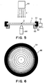
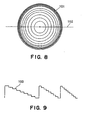
- Figure 8 shows an example of a binary optics, wherein denoted at 101 is a diffractive optical element.
- Figure 9 shows a sectional shape of the diffractive optical element 101, along a line 102 in Figure 8.
- a diffraction efficiency not less than 95% can be kept for first-order diffraction light.
- the pitch of a periodic structure of the diffractive optical element should be made small as much as possible.
- a lithographic procedure having been advanced and improved through the semiconductor manufacture is used for production of high performance diffractive optical elements. Since a diffractive optical element is produced through a lithographic process, a product element is a thin plate-like member.
- a ring-like holding member (hereinafter, cell) having a thickness larger than the diffractive optical element may be bonded to a peripheral edge portion of the diffractive optical element into an integral structure, to thereby assure a required strength, and the diffractive optical element may be held together with the cell by the barrel of the projection optical system.
- the positioning of the cell may be accomplished on the basis of the outside diameter of the cell.
- the center of the cell and the center of the diffractive optical element must be registered with each other at a high precision. If there is misalignment between the centers of the cell and of the diffractive optical element, there will occur an eccentricity error when they are incorporated into an optical system, and a resultant aberration produced thereby will deteriorate the performance of the optical system as a whole.
- a diffractive optical element having a design wavelength ⁇ comprising: a diffractive surface for diffracting predetermined light corresponding to the design wavelength; and an alignment mark, called a mark shaped so that, with regard to the predetermined light, a phase difference corresponding to a multiple, by an integer, of the design wavelength ⁇ is produced between (i) a light ray, of the predetermined light, as transmitted through or reflected by the mark and (ii) a light ray, of the predetermined light, as transmitted through or reflected by a portion adjacent to the mark, and that, with regard to second light of a second wavelength ⁇ ' different from the design wavelength ⁇ , a phase difference not equal to a multiple, by an integer, of the second wavelength ⁇ ' is produced between (a) a light ray, of the second light, as transmitted through or reflected by the mark and (b) a light ray, of the second light, as transmitted through or reflected by a portion adjacent to the mark
- the mark may be placed at or adjacent a center of the diffractive surface and may be defined by a recess formed on the diffractive surface, and the recess may be formed with a depth effective to assure that a phase difference corresponding to a multiple, by an integer, of the design wavelength ⁇ is produced between (i) a light ray, of the predetermined light, as transmitted through or reflected by the mark and (ii) a light ray, of the predetermined light, as transmitted through or reflected by a portion adjacent to the mark, and that a phase difference not equal to a multiple, by an integer, of the second wavelength ⁇ ' is produced between (a) a light ray, of the second light, as transmitted through or reflected by the mark and (b) a light ray, of the second light, as transmitted through or reflected by a portion adjacent to the mark.
- the mark may be placed at or adjacent a center of the diffractive surface and may be defined by a protrusion formed on the diffractive surface, and the protrusion may be formed with a height effective to assure that a phase difference corresponding to a multiple, by an integer, of the design wavelength ⁇ is produced between (i) a light ray, of the predetermined light, as transmitted through or reflected by the mark and (ii) a light ray, of the predetermined light, as transmitted through or reflected by a portion adjacent to the mark, and that a phase difference not equal to a multiple, by an integer, of the second wavelength ⁇ ' is produced between (a) a light ray, of the second light, as transmitted through or reflected by the mark and (b) a light ray, of the second light, as transmitted through or reflected by a portion adjacent to the mark.
- the diffractive surface and the mark may be adapted to transmit light rays of the wavelengths ⁇ and ⁇ ', or they may be adapted to reflect light rays of the wavelengths ⁇ and ⁇ '.
- the diffractive surface may comprise a binary optics, and the diffractive surface and the mark may be formed in accordance with a lithographic process.
- the diffractive optical element may further comprise a substrate on which the diffractive surface and the mark are formed, and a metal ring for holding the substrate.
- the diffractive optical element may further comprise a metal ring, wherein the mark may be placed at a center of the diffractive surface, and the mark may be disposed at a central position of an outside circumference of the metal ring.
- the mark and the central position of the metal ring may be registered with each other, on the basis of detection of the mark by use of the second light of the second wavelength ⁇ '.
- the outside periphery of the metal ring may be cut or scraped for the registration.
- a projection optical system including a diffractive optical element as described above.
- a projection exposure apparatus for projecting a pattern onto a substrate by use of a projection optical system as described above.
- a device manufacturing method comprising the steps of: exposing a substrate with a device pattern by use of an exposure apparatus as described above; and developing the exposed substrate.
- the diffractive optical element is provided with a diffraction grating, formed on a substrate and having a periodic structure for transforming an incident wavefront into a predetermined wavefront, wherein an alignment mark is formed at or adjacent a central portion of the diffractive optical element.
- the diffractive optical element is provided with a diffraction grating of step-like sectional structure, formed on a substrate through approximation of a blazed shape on the basis of quantization, wherein an alignment mark is formed at or adjacent a central portion of the diffractive optical element.
- the alignment mark may comprise a recess or a protrusion formed on the substrate.
- the alignment mark may have a phase difference, with regard to a region around the mark, of about m ⁇ /(n-1) where m is an integer, n is a refractive index of the material of the substrate, and ⁇ is a design wavelength or a wavelength to be used for the diffractive optical element.
- the alignment mark may be detected by use of light of a wavelength different from the design wavelength ⁇ .
- the alignment mark may be formed at a desired position on the diffraction grating structure of the diffractive optical element, during the manufacture of the diffractive optical element and in accordance with a process the same as the step-like structure forming process.
- the optical element serves to transform an incident wavefront to a predetermined wavefront, wherein there is an alignment mark formed at or adjacent a central portion of the optical element.
- the optical element has a mark which is transparent with respect to a wavelength ⁇ to be used with the optical element.
- the optical element has a mark formed in a region through which exposure light is to pass, wherein the mark is transparent with respect to the exposure light.
- the optical element has an alignment mark formed in a region through which light is to pass.
- the optical element has an alignment mark formed in a region through which exposure light is to pass.
- the mark may have a phase difference, with regard to a region around the mark, of about m ⁇ /(n-1) where m is an integer, n is a refractive index of the material of the substrate of the optical element, and ⁇ is a design wavelength or a wavelength to be used for the optical element.
- the mark may be detected by use of light of a wavelength different from the design wavelength ⁇ .
- a manufacturing system for manufacturing an optical device including an optical element may comprise: a light source for emitting a plane wave of a wavelength different from a design wavelength of the optical element; a ring-like holding member bonded to a circumferential portion of the optical element and having a thickness larger than the optical element; a rotary stage for rotating the holding member; a blade for cutting or scraping a portion of the holding member; and a detecting system for detecting positional information related to an alignment mark, wherein a portion of the holding member may be cut or scraped on the basis of the positional information of the alignment mark as produced by the detecting system, such that a center of the holding member and a center of the optical element can be brought into registration with each other.
- An optical system according to the present invention may include an optical element as recited above.
- An optical device may include an optical system having an optical element as recited above, wherein imagewise information can be produced upon a predetermined surface with use of light passing through the optical system.
- a projection exposure apparatus may include an optical system having an optical element as described above, for illuminating a pattern of a first object with light passing through the optical system, and a projection optical system for projecting the pattern onto a second object.
- a device manufacturing method may include a process for illuminating a device pattern on a mask by use of light passing through an optical system having an optical element as described above so that a surface of a wafer is exposed with the pattern, and a process for developing the exposed wafer.
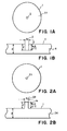
- Figures 1A and 1B are schematic illustrations of a diffractive optical element according to a first embodiment of the present invention, wherein Figure 1A is a plan view and Figure 1B is a sectional view of a main portion of the diffractive optical element.
- Figures 2A and 2B are schematic illustrations of a diffractive optical element according to a second embodiment of the present invention, wherein Figure 1A is a plan view and Figure 1B is a sectional view of a main portion of the diffractive optical element.
- Figure 3 is a plan view of a diffractive optical element according to a third embodiment of the present invention.
- Figure 4 is a schematic view for explaining an example wherein a cell is bonded to a diffractive optical element according to the present invention.
- Figure 5 is a schematic view for explaining a process for registering the center of a cell with a diffractive optical element according to the present invention.
- Figure 6 is a schematic view for explaining a process for removing any eccentric portion of a cell, mounted on a diffractive optical element.
- Figure 7 is a schematic view of an embodiment of an optical system having a diffractive optical element according to the present invention.
- Figures 8 and 9 show a conventional diffractive optical element, wherein Figure 8A is a plan view and Figure 9 is a sectional view.
- Figures 1A and 1B are schematic illustrations of a diffractive optical element (optical element) according to a first embodiment of the present invention, wherein Figure 1A is a plan view and Figure 1B is a sectional view of a main portion thereof.
- a diffractive optical element which has a diffraction grating portion 11 wherein a diffraction grating of a binary shape (step-like shape), a Kinoform shape or a Fresnel shape, for example, is formed. Also, an alignment mark (mark) 2 is formed in a central portion thereof.
- the diffractive optical element 1 is illustrated as being a transmission type.
- the present invention is applicable to a reflection type optical element.
- the diffractive optical element 1 in this embodiment has an alignment mark 2 which, as shown in Figure 1B, is formed with a small opening ⁇ and a height (depth) y adapted to provide a phase difference of about m ⁇ /(n-1) between a light ray (wavelength ⁇ ) passing through (or reflected by) the mark and a light ray (wavelength ⁇ ) passing through a portion around the mark, where ⁇ is the wavelength (design wavelength) to be used with the optical element, m is an integer, and n is the refractive index of the material of a substrate 4 of the optical element with respect to the wavelength ⁇ .
- the alignment mark 2 is disposed at a desired position on the structure of the diffractive optical element, particularly, in a region through which the light of the design wavelength ⁇ is to pass, such as, for example, at or about a center of the diffractive optical element 1.
- the alignment mark 2 produces a phase shift (phase difference) corresponding to a multiple of 2 ⁇ by an integer, relative to a region around the mark.
- the depth (height) approximately satisfying m ⁇ /(n-1) refers to a range of ⁇ 30% with respect to an idealistic value.
- a process for positioning the center of the diffractive optical element in this embodiment light of a wavelength ⁇ ' (alignment wavelength) different from the design wavelength ⁇ and satisfying about m ⁇ '/(n'-1) (where n' is the refractive index with respect to the wavelength ⁇ '), is used such that the alignment mark 2 can be practically present. While using such alignment light of the wavelength ⁇ ', a wavefront from the alignment mark 2 and from a portion around the mark is caused to interfere with a reference wavefront. On the basis of this interference, the position of the alignment mark is detected. Then, in accordance with the detection, the center of the diffractive optical element 1 can be positioned very precisely with respect to the cell.
- the cell may be machined by use of the alignment mark such that the central position of the cell with regard to a barrel may be adjusted.
- phase difference is a multiple of 2 ⁇ by an integer and, therefore, substantially it becomes equivalent to a condition where there is no phase difference.
- the system can be used substantially as one having no such alignment mark.
- the diameter of the small opening of the alignment mark may be about 1 micron and the depth thereof may be 3.45 microns.
- the alignment mark is not limited to a hole with a circular opening.
- it may comprise a protrusion 23 of a round column.
- the alignment mark 21 may comprise a round column with a diameter a and a height h that satisfies about m ⁇ /(n-1) where m is an integer.
- the phase difference to be produced between the wavefront passing through (or reflected by) a peripheral portion around the alignment mark 21 and the wavefront passing through (or reflected by) the center of the alignment mark corresponds to a multiple of 2 ⁇ by an integer. Therefore, substantially it becomes equivalent to a condition where there is no phase difference.
- the system can be used substantially as one having no such alignment mark, if used with the design wavelength ⁇ .
- the alignment mark may have a sectional shape other than a circular shape as described above.
- it may comprise a cross-shape mark 31 such as shown in Figure 3.
- the alignment mark 31 may comprise a recess or a protrusion which may be formed at or adjacent a center of the diffractive optical element 1 and formed with a depth or a height satisfying about m ⁇ /(n-1) where m is an integer.
- Figure 4 is an illustration for explaining registration between a center of an optical element having an alignment mark and a center of a cell therefor, in accordance with the present invention.
- Figure 4 is a schematic illustration of an example wherein a cell 51 is bonded to a diffractive optical element 1.
- the cell 51 comprises a holding member of ring-like shape, having a thickness larger than that of the diffractive optical element 1.
- Denoted at 52 is a fixing ring for bonding the cell 51 and the diffractive optical element 1 to each other.
- Denoted at 2 is an alignment mark which is provided at a center of the diffractive optical element 1.
- Figure 5 illustrates a centering process wherein the position of the alignment mark (mark) 2 of the diffractive optical element 1 is detected and wherein a portion (any eccentric portion) of the cell 51 is removed or scraped while rotating the cell about the central position of the mark 2.
- 61 is a light source for emitting a plane wave of a wavelength ⁇ ' different from the design wavelength ⁇ .
- Denoted at 62 is a rotary stage for holding and rotating the cell.
- Denoted at 63 is a blade for cutting or scraping the cell 51.
- Denoted at 64 is a detecting system for detecting the alignment mark 2.
- the alignment mark 2 is defined by a hole having a circular opening as shown in Figure 1 and a depth of m ⁇ /(n-1) where m is an integer.
- the cell 51 is bonded to the diffractive optical element 1, and then it is fixed by use of the fixing ring 52.
- the cell mounted in this manner is then fixedly mounted on the rotary stage 62.
- a plane wave of a wavelength ⁇ ' ( ⁇ ' ⁇ m ⁇ '(n-1) where m is an integer) is emitted from the light source 6 as illumination light, which is projected to a portion around the center of the diffractive optical element 1.
- the alignment mark 2 is so designed that the phase at a portion adjacent the mark and with respect to the design wavelength ⁇ becomes equal to a multiple of 2 ⁇ by an integer, and also there is a relation ⁇ ' ⁇ m ⁇ '(n'-1). Therefore, if a plane wave of the alignment wavelength ⁇ ' different from the design wavelength ⁇ is projected, a phase shift or deviation is produced between a light ray passing through the alignment mark 2 portion and a light ray passing through a region surrounding the mark 2 portion.
- phase difference microscope may be used in the detecting system, and the position of the alignment mark 2 can be detected precisely also in that occasion.
- the rotary stage 62 is driven by means of an X-Y stage, not shown, so that the center of the detecting system 64 (which corresponds to the rotational center of the rotary stage) and the center of the alignment mark 2 are brought into registration with each other. Then, the rotary stage 62 is rotated while holding the registration.
- the blade 63 While rotating the rotary stage 62, the blade 63 is gradually moved close to the cell 51, to remove any eccentric portion of the cell, such as depicted at 65 in Figure 6. As a result of this operation, the cell 51 is machined so that the center thereof is brought into alignment with the center of the alignment mark 2. To this end, preferably the cell 51 should have an original size larger than a desired size therefor.
- the cell 51 having its eccentric portion 65 ( Figure 6) removed in the manner described above, is in a state similar to that shown in Figure 4.
- high-precision optical axis alignment can be accomplished.
- Figure 7 is a schematic view of a main portion of an embodiment wherein an optical system having an optical element according to the present invention is incorporated into a projection exposure apparatus to be used in a lithographic process, in the device manufacturing procedure for production of microdevices such as a semiconductor device (e.g., IC or LSI), an image pickup device (e.g., CCD), or a display device (e.g., liquid crystal panel), for example.
- a semiconductor device e.g., IC or LSI
- an image pickup device e.g., CCD
- a display device e.g., liquid crystal panel
- Denoted in Figure 7 at 71 is a light source, and denoted at 72 is a reticle.
- Denoted at 73 is a lens barrel for a projection optical system 78.
- Denoted at 74 are lenses of the projection optical system, and denoted at 1 is a diffractive optical element according to the present invention.
- Denoted at 76 is a wafer, and denoted at 77 is a wafer stage.
- the diffractive optical element 1 comprises one according to the first embodiment of the present invention, for example, and here it is arranged to correct chromatic aberration of the lenses 4.
- the wafer 76 can be positioned at a desired position, by means of the wafer stage 77.
- the wafer height can be adjusted at a focus position, by means of a focus detecting system (not shown).
- the reticle may be brought into alignment with a mark of the wafer, having been printed on an underlying layer of the wafer.
- a shutter (not shown) is opened such that the reticle 72 is illuminated with illumination light from the light source 71.
- a circuit pattern formed on the reticle 72 is projected by the projection optical system 78 onto a resist applied to the wafer 76, whereby the wafer is exposed with the reticle pattern.
- the thus exposed wafer 76 is then processed by a development operation and an etching operation, for example, known in the art, whereby microdevices can be produced.
- An optical system with an optical element according to the present invention can be applied similarly to an optical instrument for image formation or to an illumination system, for example.
Landscapes
- Physics & Mathematics (AREA)
- General Physics & Mathematics (AREA)
- Optics & Photonics (AREA)
- Exposure And Positioning Against Photoresist Photosensitive Materials (AREA)
- Diffracting Gratings Or Hologram Optical Elements (AREA)
- Exposure Of Semiconductors, Excluding Electron Or Ion Beam Exposure (AREA)
- Length Measuring Devices By Optical Means (AREA)
Claims (12)
- Optisches Beugungselement mit einer Konzeptionswellenlänge λ, mit
einer beugenden Oberfläche zum Beugen von der Konzeptionswellenlänge entsprechendem, vorbestimmtem Licht, und
einer derart geformten Justiermarke, dass, im Hinblick auf das vorbestimmte Licht, zwischen (i) einem Lichtstrahl des vorbestimmten Lichts, wie er durch die Justiermarke hindurchgelassen wird oder von ihr reflektiert wird, und (ii) einem Lichtstrahl des vorbestimmten Lichts, wie er durch einen zu der Justiermarke benachbarten Bereich hindurchgelassen wird oder von ihm reflektiert wird, eine einem ganzzahligen Vielfachen der Konzeptionswellenlänge entsprechende Phasendifferenz erzeugt wird, und dass, im Hinblick auf zweites Licht mit einer von der Konzeptionswellenlänge λ verschiedenen zweiten Wellenlänge λ', zwischen (a) einem Lichtstrahl des zweiten Lichts, wie er durch die Justiermarke hindurchgelassen wird oder von ihr reflektiert wird, und (b) einem Lichtstrahl des zweiten Lichts, wie er durch einen zu der Justiermarke benachbarten Bereich hindurchgelassen wird oder von ihm reflektiert wird, eine Phasendifferenz erzeugt wird, die ungleich einem ganzzahligen Vielfachen der zweiten Wellenlänge λ' ist, wodurch eine Position der Justiermarke unter Verwendung des Lichts mit der zweiten Wellenlänge erfassbar ist. - Optisches Beugungselement nach Anspruch 1, wobei die Justiermarke bei oder benachbart zu einem Zentrum der beugenden Oberfläche platziert ist und durch eine an der beugenden Oberfläche ausgebildete Vertiefung definiert ist, und wobei die Vertiefung mit einer Tiefe ausgebildet ist, die zum Sicherstellen wirksam ist, dass zwischen (i) einem Lichtstrahl des vorbestimmten Lichts, wie er durch die Justiermarke hindurchgelassen wird oder von ihr reflektiert wird, und (ii) einem Lichtstrahl des vorbestimmten Lichts, wie er durch einen zu der Justiermarke benachbarten Bereich hindurchgelassen wird oder von ihm reflektiert wird, eine einem ganzzahligen Vielfachen der Konzeptionswellenlänge λ entsprechende Phasendifferenz erzeugt wird, und dass zwischen (a) einem Lichtstrahl des zweiten Lichts, wie er durch die Justiermarke hindurchgelassen wird oder von ihr reflektiert wird, und (b) einem Lichtstrahl des zweiten Lichts, wie er durch einen zu der Justiermarke benachbarten Bereich hindurchgelassen wird oder von ihm reflektiert wird, eine Phasendifferenz erzeugt wird, die ungleich einem ganzzahligen Vielfachen der zweiten Wellenlänge λ' ist.
- Optisches Beugungselement nach Anspruch 1, wobei die Justiermarke bei oder benachbart zu einem Zentrum der beugenden Oberfläche platziert ist und durch eine an der beugenden Oberfläche ausgebildete Auskragung definiert ist, und wobei die Auskragung mit einer Höhe ausgebildet ist, die zum Sicherstellen wirksam ist, dass zwischen (i) einem Lichtstrahl des vorbestimmten Lichts, wie er durch die Justiermarke hindurchgelassen wird oder von ihr reflektiert wird, und (ii) einem Lichtstrahl des vorbestimmten Lichts, wie er durch einen zu der Justiermarke benachbarten Bereich hindurchgelassen wird oder von ihm reflektiert wird, eine einem ganzzahligen Vielfachen der Konzeptionswellenlänge λ entsprechende Phasendifferenz erzeugt wird, und dass zwischen (a) einem Lichtstrahl des zweiten Lichts, wie er durch die Justiermarke hindurchgelassen wird oder von ihr reflektiert wird, und (b) einem Lichtstrahl des zweiten Lichts, wie er durch einen zu der Justiermarke benachbarten Bereich hindurchgelassen wird oder von ihm reflektiert wird, eine Phasendifferenz erzeugt wird, die ungleich einem ganzzahligen Vielfachen der zweiten Wellenlänge λ' ist.
- Optisches Beugungselement nach Anspruch 1, wobei die beugende Oberfläche und die Justiermarke dahingehend ausgestaltet sind, um Lichtstrahlen mit den Wellenlängen λ und λ' hindurchzulassen.
- Optisches Beugungselement nach Anspruch 1, wobei die beugende Oberfläche und die Justiermarke dahingehend ausgestaltet sind, um Lichtstrahlen mit den Wellenlängen λ und λ' zu reflektieren.
- Optisches Beugungselement nach Anspruch 1, wobei die beugende Oberfläche eine binäre Optik aufweist, und wobei die beugende Oberfläche und die Justiermarke gemäß einem lithographischen Vorgang ausgebildet sind.
- Optisches Beugungselement nach Anspruch 1, zudem mit einem Substrat, an welchem die beugende Oberfläche und die Justiermarke ausgebildet sind, und einem Metallring zum Halten des Substrats.
- Optisches Beugungselement nach Anspruch 1, zudem mit einem Metallring, wobei die Justiermarke bei einem Zentrum der beugenden Oberfläche platziert ist, und wobei die Justiermarke bei einer zentralen Position eines äußeren Umfangs des Metallrings angeordnet ist.
- Optisches Beugungselement nach Anspruch 1, wobei die Justiermarke und die zentrale Position des Metallrings auf der Grundlage der Erfassung der Justiermarke unter Verwendung des zweiten Lichts mit der zweiten Wellenlänge λ' zueinander ausgerichtet sind.
- Optisches Projektionssystem mit einem optischen Beugungselement nach einem der Ansprüche 1 bis 9.
- Projektionsbelichtungsgerät zur Projektion eines Musters auf ein Substrat unter Verwendung eines optischen Projektionssystems nach Anspruch 10.
- Vorrichtungsherstellungsverfahren, mit den Schritten des
Belichtens eines Substrats mit einem Vorrichtungsmuster unter Verwendung eines Belichtungsgeräts nach Anspruch 11,
Entwickeln des belichteten Substrats, und
Herstellen einer Vorrichtung aus dem belichteten und entwickelten Substrat.
Applications Claiming Priority (2)
| Application Number | Priority Date | Filing Date | Title |
|---|---|---|---|
| JP33342998 | 1998-11-09 | ||
| JP33342998 | 1998-11-09 |
Publications (4)
| Publication Number | Publication Date |
|---|---|
| EP1001301A2 EP1001301A2 (de) | 2000-05-17 |
| EP1001301A3 EP1001301A3 (de) | 2001-06-27 |
| EP1001301B1 EP1001301B1 (de) | 2004-06-09 |
| EP1001301B2 true EP1001301B2 (de) | 2007-10-24 |
Family
ID=18266019
Family Applications (1)
| Application Number | Title | Priority Date | Filing Date |
|---|---|---|---|
| EP99308877A Expired - Lifetime EP1001301B2 (de) | 1998-11-09 | 1999-11-08 | Optisches Element mit Justiermarke und optisches System mit einem solchen Element |
Country Status (3)
| Country | Link |
|---|---|
| US (1) | US6856392B1 (de) |
| EP (1) | EP1001301B2 (de) |
| DE (1) | DE69917865D1 (de) |
Families Citing this family (11)
| Publication number | Priority date | Publication date | Assignee | Title |
|---|---|---|---|---|
| JP3290631B2 (ja) * | 1998-10-02 | 2002-06-10 | キヤノン株式会社 | 光学ユニット、光学ユニットの製造方法、光学ユニットを用いた光学系、光学ユニットを用いた露光装置及びこの露光装置を用いたデバイスの製造方法 |
| JP2002062417A (ja) | 2000-06-07 | 2002-02-28 | Canon Inc | 回折光学素子、該回折光学素子を有する光学系及び光学機器、回折光学素子の製造方法、回折光学素子製造用の金型 |
| JP2002071923A (ja) * | 2000-08-29 | 2002-03-12 | Canon Inc | 回折光学素子の製造方法及び回折光学素子、並びに該回折光学素子を有する光学系、該光学系を有する撮影装置と観察装置 |
| DE10136387A1 (de) * | 2001-07-26 | 2003-02-13 | Zeiss Carl | Objektiv, insbesondere Objektiv für die Halbleiter-Lithographie |
| JP2006058850A (ja) * | 2004-07-22 | 2006-03-02 | Alps Electric Co Ltd | 光学レンズ及びその製造方法 |
| US7499220B2 (en) | 2003-08-08 | 2009-03-03 | Alps Electric Co., Ltd. | Optical lens and method of manufacturing the same |
| US7460460B2 (en) * | 2004-02-27 | 2008-12-02 | Konica Minolta Opto, Inc. | Objective optical system, optical pickup apparatus and optical information recording and reproducing apparatus |
| CN100349020C (zh) * | 2004-07-22 | 2007-11-14 | 阿尔卑斯电气株式会社 | 光学透镜及其制造方法 |
| WO2011053419A2 (en) * | 2009-09-29 | 2011-05-05 | 3M Innovative Properties Company | Optically transmissive substrate having a fiducial mark and methods of aligning optically transmissive substrates |
| EP3367165A1 (de) * | 2017-02-23 | 2018-08-29 | ASML Netherlands B.V. | Verfahren zum ausrichten eines beugenden optischen systems und diffraktives optisches element |
| CN111512192B (zh) * | 2018-01-03 | 2022-05-17 | 株式会社Lg化学 | 光学膜 |
Citations (2)
| Publication number | Priority date | Publication date | Assignee | Title |
|---|---|---|---|---|
| DE3852744T2 (de) † | 1987-10-25 | 1995-05-24 | Theodore Robert Woodland Hills Calif. Whitney | Hoch auflösendes abbildendes System. |
| DE69213127T2 (de) † | 1991-06-19 | 1997-01-16 | At & T Corp | Brechkraftlose Feldkorrektionslinse |
Family Cites Families (10)
| Publication number | Priority date | Publication date | Assignee | Title |
|---|---|---|---|---|
| US4636077A (en) * | 1983-04-15 | 1987-01-13 | Matsushita Electric Industrial Co., Ltd. | Aligning exposure method |
| US4614433A (en) * | 1984-07-09 | 1986-09-30 | At&T Bell Laboratories | Mask-to-wafer alignment utilizing zone plates |
| US5161059A (en) * | 1987-09-21 | 1992-11-03 | Massachusetts Institute Of Technology | High-efficiency, multilevel, diffractive optical elements |
| US5294980A (en) * | 1988-03-24 | 1994-03-15 | Canon Kabushiki Kaisha | Positioning detecting method and apparatus |
| EP0455443B1 (de) | 1990-05-01 | 1997-11-12 | Canon Kabushiki Kaisha | Verfahren und Apparat zur Detektion von Lageabweichungen |
| JP2913855B2 (ja) | 1991-01-18 | 1999-06-28 | 日本電気株式会社 | 半導体装置のアライメント誤差解析装置 |
| JPH07253528A (ja) | 1994-03-16 | 1995-10-03 | Olympus Optical Co Ltd | 光軸調整装置 |
| JPH0883747A (ja) * | 1994-09-09 | 1996-03-26 | Nikon Corp | アライメントマークを有する光学部材 |
| JP3287236B2 (ja) * | 1996-10-03 | 2002-06-04 | キヤノン株式会社 | 回折光学素子の製作方法 |
| JPH10135118A (ja) | 1996-10-28 | 1998-05-22 | Canon Inc | 投影露光装置 |
-
1999
- 1999-11-05 US US09/434,300 patent/US6856392B1/en not_active Expired - Fee Related
- 1999-11-08 EP EP99308877A patent/EP1001301B2/de not_active Expired - Lifetime
- 1999-11-08 DE DE69917865T patent/DE69917865D1/de not_active Expired - Lifetime
Patent Citations (2)
| Publication number | Priority date | Publication date | Assignee | Title |
|---|---|---|---|---|
| DE3852744T2 (de) † | 1987-10-25 | 1995-05-24 | Theodore Robert Woodland Hills Calif. Whitney | Hoch auflösendes abbildendes System. |
| DE69213127T2 (de) † | 1991-06-19 | 1997-01-16 | At & T Corp | Brechkraftlose Feldkorrektionslinse |
Non-Patent Citations (1)
| Title |
|---|
| J.R. Sheats et al. Microlithography: Science and Technology (Marcel Dekker Inc) 1998, S. 244-253 † |
Also Published As
| Publication number | Publication date |
|---|---|
| US6856392B1 (en) | 2005-02-15 |
| EP1001301B1 (de) | 2004-06-09 |
| EP1001301A3 (de) | 2001-06-27 |
| DE69917865D1 (de) | 2004-07-15 |
| EP1001301A2 (de) | 2000-05-17 |
Similar Documents
| Publication | Publication Date | Title |
|---|---|---|
| EP0834751B1 (de) | Verfahren zur Herstellung eines optischen Elements | |
| JP3463335B2 (ja) | 投影露光装置 | |
| TWI474132B (zh) | 照明光學裝置、投影曝光裝置、曝光方法以及元件製造方法 | |
| JP4497968B2 (ja) | 照明装置、露光装置及びデバイス製造方法 | |
| US6008942A (en) | Diffractive optical element and optical instrument having the same | |
| EP1001301B2 (de) | Optisches Element mit Justiermarke und optisches System mit einem solchen Element | |
| JP2004258670A (ja) | 高開口数システムの固定および動的ラジアル横方向電気偏光器 | |
| US20070287073A1 (en) | Lithography systems and methods | |
| US6222198B1 (en) | System and method for aligning pattern areas on opposing substrate surfaces | |
| US6462875B1 (en) | Diffractive optical element | |
| JP3290631B2 (ja) | 光学ユニット、光学ユニットの製造方法、光学ユニットを用いた光学系、光学ユニットを用いた露光装置及びこの露光装置を用いたデバイスの製造方法 | |
| JP3408112B2 (ja) | 回折光学素子を有した光学部材及びそれを用いた光学系 | |
| JP2001272764A (ja) | 投影露光用フォトマスク、およびそれを用いた投影露光方法 | |
| US5663785A (en) | Diffraction pupil filler modified illuminator for annular pupil fills | |
| JPH07122469A (ja) | 投影露光装置 | |
| JP4750525B2 (ja) | 露光方法及びデバイス製造方法 | |
| US5291319A (en) | Rotating disc optical synchronization system using binary diffractive optical elements | |
| JP3997199B2 (ja) | 露光方法及び装置 | |
| JP3429525B2 (ja) | 投影レンズ系 | |
| JP2006245270A (ja) | 露光装置及び露光方法 | |
| JP2007035709A (ja) | 露光装置及びそれを用いたデバイス製造方法 | |
| US6611376B1 (en) | Diffractive optical element and method of manufacturing the same | |
| JP3332896B2 (ja) | 回折光学素子及びそれを有した光学系 | |
| JP3313932B2 (ja) | 投影露光装置 | |
| JP2001272310A (ja) | 投影光学系の収差計測装置及び計測方法、それに用いられるマスク並びに露光装置 |
Legal Events
| Date | Code | Title | Description |
|---|---|---|---|
| PUAI | Public reference made under article 153(3) epc to a published international application that has entered the european phase |
Free format text: ORIGINAL CODE: 0009012 |
|
| AK | Designated contracting states |
Kind code of ref document: A2 Designated state(s): DE GB NL |
|
| AX | Request for extension of the european patent |
Free format text: AL;LT;LV;MK;RO;SI |
|
| PUAL | Search report despatched |
Free format text: ORIGINAL CODE: 0009013 |
|
| AK | Designated contracting states |
Kind code of ref document: A3 Designated state(s): AT BE CH CY DE DK ES FI FR GB GR IE IT LI LU MC NL PT SE |
|
| AX | Request for extension of the european patent |
Free format text: AL;LT;LV;MK;RO;SI |
|
| RIC1 | Information provided on ipc code assigned before grant |
Free format text: 7G 02B 27/32 A, 7G 02B 27/62 B, 7G 02B 5/18 B, 7G 02B 7/00 B |
|
| 17P | Request for examination filed |
Effective date: 20011109 |
|
| AKX | Designation fees paid |
Free format text: DE GB NL |
|
| 17Q | First examination report despatched |
Effective date: 20020606 |
|
| GRAP | Despatch of communication of intention to grant a patent |
Free format text: ORIGINAL CODE: EPIDOSNIGR1 |
|
| GRAS | Grant fee paid |
Free format text: ORIGINAL CODE: EPIDOSNIGR3 |
|
| GRAA | (expected) grant |
Free format text: ORIGINAL CODE: 0009210 |
|
| AK | Designated contracting states |
Kind code of ref document: B1 Designated state(s): DE GB NL |
|
| PG25 | Lapsed in a contracting state [announced via postgrant information from national office to epo] |
Ref country code: NL Free format text: LAPSE BECAUSE OF FAILURE TO SUBMIT A TRANSLATION OF THE DESCRIPTION OR TO PAY THE FEE WITHIN THE PRESCRIBED TIME-LIMIT Effective date: 20040609 |
|
| REG | Reference to a national code |
Ref country code: GB Ref legal event code: FG4D |
|
| REF | Corresponds to: |
Ref document number: 69917865 Country of ref document: DE Date of ref document: 20040715 Kind code of ref document: P |
|
| PG25 | Lapsed in a contracting state [announced via postgrant information from national office to epo] |
Ref country code: DE Free format text: LAPSE BECAUSE OF FAILURE TO SUBMIT A TRANSLATION OF THE DESCRIPTION OR TO PAY THE FEE WITHIN THE PRESCRIBED TIME-LIMIT Effective date: 20040910 |
|
| NLV1 | Nl: lapsed or annulled due to failure to fulfill the requirements of art. 29p and 29m of the patents act | ||
| PLAQ | Examination of admissibility of opposition: information related to despatch of communication + time limit deleted |
Free format text: ORIGINAL CODE: EPIDOSDOPE2 |
|
| PLBI | Opposition filed |
Free format text: ORIGINAL CODE: 0009260 |
|
| PLBQ | Unpublished change to opponent data |
Free format text: ORIGINAL CODE: EPIDOS OPPO |
|
| 26 | Opposition filed |
Opponent name: CARL ZEISS SMT AG Effective date: 20050308 |
|
| PLAQ | Examination of admissibility of opposition: information related to despatch of communication + time limit deleted |
Free format text: ORIGINAL CODE: EPIDOSDOPE2 |
|
| PLAR | Examination of admissibility of opposition: information related to receipt of reply deleted |
Free format text: ORIGINAL CODE: EPIDOSDOPE4 |
|
| PLAX | Notice of opposition and request to file observation + time limit sent |
Free format text: ORIGINAL CODE: EPIDOSNOBS2 |
|
| PLBQ | Unpublished change to opponent data |
Free format text: ORIGINAL CODE: EPIDOS OPPO |
|
| PLAB | Opposition data, opponent's data or that of the opponent's representative modified |
Free format text: ORIGINAL CODE: 0009299OPPO |
|
| R26 | Opposition filed (corrected) |
Opponent name: CARL ZEISS SMT AG Effective date: 20050308 |
|
| PLAF | Information modified related to communication of a notice of opposition and request to file observations + time limit |
Free format text: ORIGINAL CODE: EPIDOSCOBS2 |
|
| PLBB | Reply of patent proprietor to notice(s) of opposition received |
Free format text: ORIGINAL CODE: EPIDOSNOBS3 |
|
| PLAB | Opposition data, opponent's data or that of the opponent's representative modified |
Free format text: ORIGINAL CODE: 0009299OPPO |
|
| R26 | Opposition filed (corrected) |
Opponent name: CARL ZEISS SMT AG Effective date: 20050308 |
|
| PUAH | Patent maintained in amended form |
Free format text: ORIGINAL CODE: 0009272 |
|
| STAA | Information on the status of an ep patent application or granted ep patent |
Free format text: STATUS: PATENT MAINTAINED AS AMENDED |
|
| 27A | Patent maintained in amended form |
Effective date: 20071024 |
|
| AK | Designated contracting states |
Kind code of ref document: B2 Designated state(s): DE GB NL |
|
| PGFP | Annual fee paid to national office [announced via postgrant information from national office to epo] |
Ref country code: GB Payment date: 20151125 Year of fee payment: 17 |
|
| GBPC | Gb: european patent ceased through non-payment of renewal fee |
Effective date: 20161108 |
|
| PG25 | Lapsed in a contracting state [announced via postgrant information from national office to epo] |
Ref country code: GB Free format text: LAPSE BECAUSE OF NON-PAYMENT OF DUE FEES Effective date: 20161108 |