EP1001402A2 - Presentation system - Google Patents
Presentation system Download PDFInfo
- Publication number
- EP1001402A2 EP1001402A2 EP99122206A EP99122206A EP1001402A2 EP 1001402 A2 EP1001402 A2 EP 1001402A2 EP 99122206 A EP99122206 A EP 99122206A EP 99122206 A EP99122206 A EP 99122206A EP 1001402 A2 EP1001402 A2 EP 1001402A2
- Authority
- EP
- European Patent Office
- Prior art keywords
- section
- posts
- presentation system
- presentation
- post
- Prior art date
- Legal status (The legal status is an assumption and is not a legal conclusion. Google has not performed a legal analysis and makes no representation as to the accuracy of the status listed.)
- Withdrawn
Links
- 230000000694 effects Effects 0.000 claims description 3
- 239000007787 solid Substances 0.000 claims 1
- 230000007704 transition Effects 0.000 claims 1
- 238000005192 partition Methods 0.000 description 7
- 239000000843 powder Substances 0.000 description 7
- 229910000831 Steel Inorganic materials 0.000 description 6
- 239000010959 steel Substances 0.000 description 6
- 238000009434 installation Methods 0.000 description 4
- 238000004519 manufacturing process Methods 0.000 description 4
- 238000010276 construction Methods 0.000 description 3
- 239000000123 paper Substances 0.000 description 3
- 238000004904 shortening Methods 0.000 description 3
- 229910000838 Al alloy Inorganic materials 0.000 description 2
- 238000004026 adhesive bonding Methods 0.000 description 2
- XAGFODPZIPBFFR-UHFFFAOYSA-N aluminium Chemical compound [Al] XAGFODPZIPBFFR-UHFFFAOYSA-N 0.000 description 2
- 229910052782 aluminium Inorganic materials 0.000 description 2
- 230000008901 benefit Effects 0.000 description 2
- 230000015572 biosynthetic process Effects 0.000 description 2
- 239000004744 fabric Substances 0.000 description 2
- 239000000463 material Substances 0.000 description 2
- 239000004952 Polyamide Substances 0.000 description 1
- 239000011111 cardboard Substances 0.000 description 1
- 239000000969 carrier Substances 0.000 description 1
- 230000008859 change Effects 0.000 description 1
- 239000002131 composite material Substances 0.000 description 1
- 230000008878 coupling Effects 0.000 description 1
- 238000010168 coupling process Methods 0.000 description 1
- 238000005859 coupling reaction Methods 0.000 description 1
- 239000010408 film Substances 0.000 description 1
- 230000003993 interaction Effects 0.000 description 1
- 239000004033 plastic Substances 0.000 description 1
- 239000002985 plastic film Substances 0.000 description 1
- 229920006255 plastic film Polymers 0.000 description 1
- 229920002647 polyamide Polymers 0.000 description 1
- 230000036316 preload Effects 0.000 description 1
- 239000012858 resilient material Substances 0.000 description 1
- 230000000284 resting effect Effects 0.000 description 1
- 238000009958 sewing Methods 0.000 description 1
- 125000006850 spacer group Chemical group 0.000 description 1
- 229920002994 synthetic fiber Polymers 0.000 description 1
- 230000007306 turnover Effects 0.000 description 1
Images


Classifications
-
- G—PHYSICS
- G09—EDUCATION; CRYPTOGRAPHY; DISPLAY; ADVERTISING; SEALS
- G09F—DISPLAYING; ADVERTISING; SIGNS; LABELS OR NAME-PLATES; SEALS
- G09F15/00—Boards, hoardings, pillars, or like structures for notices, placards, posters, or the like
- G09F15/0068—Modular articulated structures, e.g. stands, and articulation means therefor
-
- A—HUMAN NECESSITIES
- A47—FURNITURE; DOMESTIC ARTICLES OR APPLIANCES; COFFEE MILLS; SPICE MILLS; SUCTION CLEANERS IN GENERAL
- A47F—SPECIAL FURNITURE, FITTINGS, OR ACCESSORIES FOR SHOPS, STOREHOUSES, BARS, RESTAURANTS OR THE LIKE; PAYING COUNTERS
- A47F5/00—Show stands, hangers, or shelves characterised by their constructional features
- A47F5/10—Adjustable or foldable or dismountable display stands
- A47F5/13—Adjustable or foldable or dismountable display stands made of tubes or wire
-
- E—FIXED CONSTRUCTIONS
- E04—BUILDING
- E04B—GENERAL BUILDING CONSTRUCTIONS; WALLS, e.g. PARTITIONS; ROOFS; FLOORS; CEILINGS; INSULATION OR OTHER PROTECTION OF BUILDINGS
- E04B2/00—Walls, e.g. partitions, for buildings; Wall construction with regard to insulation; Connections specially adapted to walls
- E04B2/74—Removable non-load-bearing partitions; Partitions with a free upper edge
- E04B2/7407—Removable non-load-bearing partitions; Partitions with a free upper edge assembled using frames with infill panels or coverings only; made-up of panels and a support structure incorporating posts
- E04B2/7416—Removable non-load-bearing partitions; Partitions with a free upper edge assembled using frames with infill panels or coverings only; made-up of panels and a support structure incorporating posts with free upper edge, e.g. for use as office space dividers
- E04B2/7422—Removable non-load-bearing partitions; Partitions with a free upper edge assembled using frames with infill panels or coverings only; made-up of panels and a support structure incorporating posts with free upper edge, e.g. for use as office space dividers with separate framed panels without intermediary support posts
- E04B2/7427—Removable non-load-bearing partitions; Partitions with a free upper edge assembled using frames with infill panels or coverings only; made-up of panels and a support structure incorporating posts with free upper edge, e.g. for use as office space dividers with separate framed panels without intermediary support posts with adjustable angular connection of panels
- E04B2/7431—Removable non-load-bearing partitions; Partitions with a free upper edge assembled using frames with infill panels or coverings only; made-up of panels and a support structure incorporating posts with free upper edge, e.g. for use as office space dividers with separate framed panels without intermediary support posts with adjustable angular connection of panels using hinges having two parallel rotation axes
Definitions
- the present invention relates to a presentation system according to the preamble of claim 1.
- Such presentation systems also called displays, can be found primarily at exhibitions or trade fairs for presentation from graphic information in particular to primarily flexible information carriers such as paper, cardboard, plastic films, Fabric or fabric panels etc. in large quantities Use. They often serve as room dividers at the same time.
- the one on the floor in the The foot resting on the right angle to the lower bar is at the end connected to one end of a telescopic rod, which itself extends vertically from the foot upwards and also at right angles runs to the bottom bar.
- the other end of the telescopic pole has a mounting section for each outer elastically curved element.
- Each frame consists of two parallel, vertically extending side sections, a foot section connecting the side sections and one upper connecting section provided between the side sections, the parallel to the foot section or below is arranged at an angle to the side sections.
- the frame frames are at the top and bottom using spacer elements connected and pivotable relative to each other.
- DE 90 01 742 U1 also discloses a display panel arrangement with at least two frames, both on their sides have parallel legs, which are connected above and below by a cross member. On Leg of one frame is on one leg of the adjacent one Frame by means of two height-spaced swivel connections connected, each having a gear pair.
- This display panel arrangement is also in terms of size the individual frame little flexible. Beyond that is special the formation of the swivel connections is proportionate complex.
- a partition is also known from DE 30 26 305 A1, composed of support posts and partition elements is.
- the partition elements have a rigid partition plate that is surrounded by a frame.
- the frame is made of four a U-profile having spar ends formed, their abutting Ends attached to each other by means of connecting pieces are. These connecting pieces are designed as elbows, whose legs protrude into the spar ends and with these are on the one hand tense and on the other hand jammed. Hooks are formed on the connecting pieces of the partition elements, by means of which the partition elements in on the support posts attached eyelets can be hung.
- the partition has one stable construction. However, it is suitable due to its weight and the given size of their elements as well as their relative complex assembly only conditionally for flexible use especially fairs. In terms of size and weight The same finally applies to those in DE 85 28 710 U1 disclosed wall, which consists of several by means of coupling elements there are detachably coupled wall elements.
- the invention is based on the prior art according to the EP 0 231 447 A1 is based on the object of a simple design To create a presentation system that is as flexible as possible is and can be easily and safely assembled and disassembled.
- the form-fitting prevents Fixing the ends of the tensioning elements to the posts Vertical post that the lower end of the presentation section due to e.g. Drafts oscillate back and forth and the presentation section may be damaged becomes.
- Great flexibility of the presentation system according to the invention does not follow solely from the fact that the presentation system due to the detachable connection between the posts and the cross members can be folded such that it has compact dimensions when dismantled and thus can be easily transported to different locations. Rather, the arrangement that can be moved along the posts permits of the tensioning element also meet the respective requirements corresponding extension or shortening of the presentation section, the moreover in the connected state the posts and cross members can be made, i.e. without that entire presentation system would have to be dismantled.
- each post consists of at least one tubular element with an annular cross section.
- the posts are not just attractive Exterior, but also have a low weight, which in the With regard to easy transportation of the presentation system is an advantage.
- the length of the posts and thus the level of the presentation system to the respective requirements can be easily changed accordingly, so that in particular in interaction with the sliding arrangement of the Clamping element gives a variety of design options.
- the claim 3 provides that the tensioning element on Presentation section attached, preferably massive Has basic body.
- the tensioning element on Presentation section attached preferably massive Has basic body.
- the Basic body can about the own weight of the Basic body depending on the material of the presentation section for a defined preload of the presentation section be taken care of in particular the danger counter the tearing of the presentation section.
- the base body of the clamping element each have a tubular segment with a circular segment Cross section attached, which the respective end of the clamping element forms what, among other things with regard to the production costs can be rated as cheap because standard parts, i.e. for example sections or segments of standardized pipes can be used that are readily available on the market.
- the inner diameter the pipe segments of the clamping element slightly larger than that Outside diameter of the tubular elements of the posts, with the central axes of the pipe segments parallel in a common plane run to each other, with the central axes facing each other Pipe elements essentially coincide and perpendicular to the central axis of the base body of the clamping element stand.
- the claim 7 provides that the pipe segments of the Clamping element on the inner circumference each with an elastic Lining, preferably a felt section, to effect the rubbing engagement with the posts. This is about it is not just a simple measure to the frictional engagement to effect. Rather, for example, felt sections advantageous on the pipe segments of the clamping element also provided retrospectively or in the event of repeated wear Easy assembly and disassembly of the presentation system be replaced.
- an elastic Lining preferably a felt section
- system connectors are provided to two adjacent posts To connect pairs of posts by friction, being at two system connectors one at the bottom of the adjacent one Posts and one placed at the top of the adjacent posts is.
- the provision of system connectors causes on a further increase in the flexibility of the presentation system because the width and arrangement of the presentation system by connecting independent, each from a pair of posts, a lower and an upper cross member as well a presentation section with an associated clamping element existing Units according to the respective requirements can be adjusted.
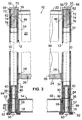
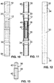
- Claim 9 provides that the tubular element with respect symmetrical about a plane perpendicular to its central axis is formed and each end has an internal thread section having. On the one hand, this has the advantage that the tubular element is easy to manufacture. On the other hand, there is one non-directional assembly of the tubular element possible, which is the structure of the presentation system.
- the contiguous Pipe elements of a post by means of a connecting element seamlessly connected the connecting element has an externally threaded portion which is in the adjacent Screwed internal thread sections of the corresponding pipe elements is. Due to the seamless connection of the pipe elements is a problem-free sliding along the tensioning element the entire length of the posts possible. Furthermore allows such a connecting element a simple and safe installation or extension according to requirements / Shortening the posts with little effort and especially without the need to use special Tools.
- connection element has a centering section, which connects to the external thread section and its Outside diameter is smaller than the outside diameter of the Male thread section, as specified in claim 11, assembly is further simplified because the connecting element not only angularly positioned with respect to the corresponding tubular element must be so that the external thread section of the Connecting element with the internal thread section of the tubular element can engage in screw engagement.
- the connecting element has one Internal thread section for fastening the foot element or of the system connector on the corresponding post.
- Claim 13 provides that the lower and the upper Cross element each have a hollow profile section whose ends each have a tubular section with an annular Cross section is fixed, the central axes of the pipe sections run parallel to each other in a common plane and perpendicular to the central axis of the hollow profile section stand.
- the cross elements thus have sufficient stability not just an advantageous light weight, but are also inexpensive and easy to manufacture because standard parts, i.e. standardized profiles or pipes are used that are easily available on the market. Furthermore is by the symmetrical design of the transverse elements is an undirected one Assembly possible (no left or right or upper or lower Side of the cross member) what the assembly of the presentation system simplified.
- Claims 14 and 15 give advantageous designs which, among other things the detachable frame-like connection of the Serve cross members with the posts. So is according to the claim 14 provided that the foot element or the system connector by means of a screw part with the respective pipe section of the corresponding cross element clamped non-positively is, the screw part with the internal thread portion the connecting element is in screw engagement, which in turn with its external thread section in the Internal thread section of the nearest pipe element of the corresponding post is screwed in and in the respective Pipe section of the corresponding cross member protrudes.
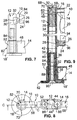
- the upper cross member at an upper, free corner of the presentation system with the nearest pipe element of the corresponding post using a plug connected to a shoulder portion rests on the respective pipe section of the upper cross element, engages tightly with one paragraph and with his End whose outer diameter is slightly smaller than that Inner diameter of the internally threaded section of the tubular element, is inserted into the nearest pipe element. So is it to connect the upper cross member to an outer one Post only necessary, a simple plug in the pipe section of the upper cross member and the corresponding Insert pipe element, no tools is needed.
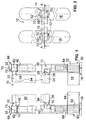
- the presentation system 10 has a pair of posts 12, a lower one Cross member 14 and an upper cross member 16, the pair Posts 12 are assigned two foot elements 18, each are connected to one of the posts 12, and one between the post 12 and the associated cross members 14, 16 extending, flexible presentation section 20 which with attached its upper end 22 to the upper cross member 16 is.
- the posts 12 and the transverse elements 14, 16 releasably like a frame connected with each other.
- a rod-shaped clamping element 26 is attached, whose ends 28 in the longitudinal direction of the posts 12 slidably disposed relative to the posts 12 and perpendicular to the posts 12 on the posts 12 are specified, which will be discussed in more detail below becomes.
- Each of the posts 12 has at least one tubular element 30 preferably aluminum or an aluminum alloy, which has an annular cross section.
- the tubular element 30 is shown in a plan view. That on has preferably deburred tubular element 30 deburred an anodized surface and is perpendicular to one its center axis 32 extending plane is symmetrical, so that it can be easily manufactured and an undirected Assembly is possible.
- the pipe element faces 30 one in relation to the total length of the tubular element 30 short internal thread section 34 (dashed in Fig. 12 shown), the connection of adjacent pipe elements 30 or the attachment of other parts.
- Exists Post 12 made of a plurality of tubular elements 30, i.e. at least two pipe elements 30, as shown in FIGS.
- connection element 36 which in Fig. 13 in A plan view is shown and preferably made of a plastic like polyamide, seamlessly connected.
- the connecting element 36 has an externally threaded section 38 which, 10 and 11 illustrate, in the neighboring Internally threaded sections 34 of the corresponding tubular elements 30 is screwed in. Closes on the external thread section 38 a cylindrical centering section 40 whose outer diameter is smaller than the outside diameter of the outside thread section 38.
- the connecting element 36 another one over the entire length of the connecting element 36 extending internal thread section 42 (dashed in Fig.
- FIG. 17 is a plan view Variant 36 'of the connecting element 36 with an external thread section 38 ', centering section 40' and internal thread section 42 '(shown in dashed lines) shows that primarily at the top End 46 such post 12 is used with a further posts 12 connected by the system connector 44 ' are (see in particular Fig.
- the lower cross member 14 is in one Front view or a plan view shown. That is preferable made of steel and powder-coated on its outer surface lower cross member 14 has a hollow profile section 48 with a rectangular outer cross-section, corresponding to it recessed ends 50 each have a tube section 52 fixed flush with an annular cross section, for example is soldered or welded, with the central axes 54 of the pipe sections 52 parallel in a common plane run to each other and perpendicular to the central axis 56 of the Stand hollow section 48, so that the lower cross member 14 with respect to the central axis 56 of the hollow profile section 48 vertical plane is symmetrical.
- the inner diameter of the pipe sections 52 is slightly larger than the outer diameter of the male threaded portion 38 of the Connecting element 36.
- the central axes 64 which is preferably on the hollow profile section 58 welded or soldered pipe sections 62 run in a common plane parallel to each other and are perpendicular to the central axis 66 of the hollow profile section 58, so that the upper cross member 16 with respect to the central axis 66 of the hollow section 58 vertical plane symmetrical is.
- the inside diameter of the pipe sections 62 is slightly larger than the external diameter of the external thread section 38 'of the connecting element 36'.
- FIGS. 1 to 3 the upper cross member 16 at an upper, free corner 68 of the presentation system 10, i.e. 1 to 3 on both sides, with the nearest pipe element 30 of the corresponding post 12 is connected by means of a plug 70 which in FIG. 16 is shown in more detail in a top view.
- a plug 70 which in FIG. 16 is shown in more detail in a top view.
- the preferred made of aluminum or an aluminum alloy, one Plug 70 having a powder-coated surface has a cylindrical shoulder portion 72 to which a cylindrical Paragraph 74 of smaller diameter, which in turn over a 45 ° bevel into a chamfered, cylindrical At the end of 76 even smaller diameter passes into the starting from its front, also for weight reasons Blind bore 78 (shown in dashed lines in Fig. 16) introduced can be.
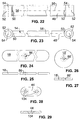
- the lower cross element 14 in the area of a lower, free corner 82 of the presentation system 10, i.e. 1 and 3 on both sides, on the respective lower ends 84 of the corresponding posts 12 below Using the foot element 18 attached. That has in 24 and 25 in a plan view and a front view shown, preferably made of sheet steel and a foot element 18 having a powder-coated surface in the middle an obliquely countersunk through hole 86 (in FIG. 25 shown in dashed lines) for receiving a screw part 88 (for example a countersunk screw), which one accordingly beveled head 90, preferably with a hexagon socket and an adjoining external thread section 92 for screw engagement with the internal thread section 42 of the connecting element 36.
- a screw part 88 for example a countersunk screw
- screw part 88 By means of the screw part 88 is the elongated one with rounded ends Foot element 18 with the respective tube section 52 of the lower one Cross member 14 clamped non-positively, which is Screw part 88 with the internal thread section 42 of the connecting element 36 is in screw engagement, which in turn with its external thread section 38 into the internal thread section 34 of the closest tubular element 30 of the corresponding one Post 12 is screwed and in the respective Pipe section 52 of the lower cross member 14 protrudes.
- the one diametrically opposite the upper end 22 lower end 24 of the presentation section 20 accordingly designed as a loop into which the tensioning element 26 is inserted.
- 1 and 3 are seams 94 for training the loops are shown in dashed lines.
- the loops can, however, also by gluing the respective end 22, 24 of the presentation section 20 or by another connection be formed, which also after assembly of the above Framework can be done.
- the preferably made of steel and having a powder coated surface Clamping element 26 has one at the lower end 24 of the presentation section 20 attached as described above, preferably massive base body 96 with a round cross section.
- On the correspondingly recessed ends 98 of the base body 96 each have a tubular segment with a circular segment Cross-section and a segment angle less than 180 °, which is slightly on each side in the direction of its central axis 100 protrudes over the base body 96 and the respective Forms end 28 of the clamping element 26.
- the clamping element 26 is thus related one perpendicular to the central axis 102 of the base body 96 Level symmetrical.
- the inside diameter of the pipe segments 28 of the clamping element 26 is slightly larger than the outer diameter of the tubular elements 30 of the posts 12, wherein in the assembled state of the clamping element 26, the central axes 100 of the pipe segments 28 with the central axes 32 opposite one another Pipe elements 30 of the pair of posts 12 in essentially coincide, so that the clamping element 26 perpendicular fixed to the posts 12 in a form-fitting manner on the posts 12, arranged in the direction of the posts 12 but slidably is. As a result, the presentation section becomes 20th by the weight of the tensioning element guided on the post 12 26 excited.
- the clamping element 26 in the longitudinal direction the post 12 with the post 12 additionally in frictional engagement stand so that the clamping element 26 only with application a predetermined force relative to the post 12 is.
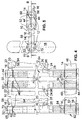
- 4 to 6 is a second embodiment of the Presentation system 10 shown in the assembled state, with reference to in particular FIGS. 1 to 3 described first embodiment corresponding parts are provided with the same reference numerals and in the following not be described again.
- the second embodiment differs from the first embodiment in that several pairs of posts 12 are associated with each Cross elements 14, 16, presentation section 20 and clamping element 26 to enlarge the presentation area with each other are connected.
- 4 to 6 are for clarity only one end of the presentation system 10 for the sake of it and the first connection of two pairs of posts 12 is shown; further pairs of posts 12 can be connected accordingly become.
- FIG Embodiment two system connectors 44, 44 ' is provided, one of which 44 at the lower end 84 of the adjacent Posts 12 and a 44 'at the top 46 of the adjacent one Post 12 is arranged.
- 28 and 29 as well 18 and 19 show the system connectors 44, 44 'in a top view or a front view.
- connection of the system connector 44, 44 'to the corresponding posts 12 is carried out analogously to that above described connection of the foot elements 18, i.e. under a Screw engagement through the through holes 104, 104 'extending screw parts 88 with in the nearest pipe elements 30 screwed connecting elements 36, 36 ', the pipe sections 52, 62 of the corresponding Cross elements 14, 16 on their end faces between the respective system connector 44, 44 'and the respective Pipe element 30 clamped.
- This allows adjacent posts 12 reliably connected to each other in an exactly parallel alignment be, it is also possible to neighboring lower cross elements 14 or upper cross elements 16 in a predetermined Fix the angular position to each other. It should be noted in this connection still that the lower system connector 44 like the foot elements 18 on the base of the presentation system 10 or lie on the floor.
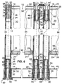
- FIG. 7 to 9 is a third embodiment of the Presentation system 10 shown in the assembled state, with reference to in particular FIGS. 1 to 6 corresponding embodiments with corresponding parts are provided with the same reference symbols and not subsequently be described again.
- the third embodiment differs from the second embodiment in that that at the free, lower corners 82 of the presentation system 10 another foot element 18 'is provided, which in the 26 and 27 in a plan view and a front view is shown. That preferably from a steel sheet has powder-coated surface existing foot element 18 ' a circular shape in plan view and is corresponding the foot element 18 in the center with a through hole 86 '(in Fig. 27 shown in dashed lines) for receiving the screw part 88 provided.
- the attachment of the foot element 18 'on outer post 12 is carried out analogously to the attachment described above of the foot element 18 and therefore will not be repeated explained.
- This foot element that offers less torque support 18 ' is used in particular when several Pairs of posts 12, each with associated cross members 14, 16, presentation section 20 and clamping element 26 with each other be connected and the stability of the presentation system 10 is achieved by the adjacent transverse elements 14, 16 of at least two pairs of posts 12 in include an angle of significantly less than 180 ° from the top view.
- FIGS. 30 to 35 show a basic illustration finally arrangement or structure variants of the presentation system 10, each of which is at least one of a Pair of posts 12, a lower cross member 14, an upper Cross member 16, a presentation section 20 and one Has clamping element 26 existing unit E.
- the size of the presentation area additionally by lengthening / shortening the presentation sections 20 (change the height of the posts 12 by adding / removing of tubular elements 30 or slidable connection of the Clamping elements 26 on the posts 12) the respective requirements can be easily adjusted accordingly.
- a presentation system with at least one pair of posts, a lower and an upper cross member that the pair Posts are assigned at least one foot element that with one of the posts is connected, and one is between the Post and the associated cross members extending, flexible Presentation section reveals that with its upper End is attached to the upper cross member.
- the posts and the cross members frame-like detachable with each other connected, being at the bottom of the presentation section a rod-shaped clamping element is attached, the Ends in the longitudinal direction of the posts relative to the Posts slidably arranged and perpendicular to the posts are positively attached to the posts.
Landscapes
- Engineering & Computer Science (AREA)
- Architecture (AREA)
- Physics & Mathematics (AREA)
- Civil Engineering (AREA)
- Theoretical Computer Science (AREA)
- Electromagnetism (AREA)
- General Physics & Mathematics (AREA)
- Structural Engineering (AREA)
- Mutual Connection Of Rods And Tubes (AREA)
- Invalid Beds And Related Equipment (AREA)
- Road Signs Or Road Markings (AREA)
- Liquid Crystal Substances (AREA)
- Separation By Low-Temperature Treatments (AREA)
- Eye Examination Apparatus (AREA)
Abstract
Description
Die vorliegende Erfindung bezieht sich auf ein Präsentationssystem
gemäß dem Oberbegriff des Patentanspruchs 1.The present invention relates to a presentation system
according to the preamble of
Derartige Präsentationssysteme, auch Displays genannt, finden in erster Linie auf Ausstellungen oder Messen zur Präsentation von insbesondere graphischen Informationen auf vornehmlich flexiblen Informationsträgern wie Papier, Pappe, Kunststofffolien, Gewebe- bzw. Stoffbahnen etc. in großen Stückzahlen Verwendung. Dabei dienen sie oftmals gleichzeitig als Raumteiler.Such presentation systems, also called displays, can be found primarily at exhibitions or trade fairs for presentation from graphic information in particular to primarily flexible information carriers such as paper, cardboard, plastic films, Fabric or fabric panels etc. in large quantities Use. They often serve as room dividers at the same time.
Im Stand der Technik fehlt es nicht an Vorschlägen, wie derartige Präsentationssysteme auszubilden sind. So offenbart die gattungsbildende EP 0 231 447 A1 ein Präsentationssystem mit einem flexiblen Präsentationsabschnitt, der zwischen einer oberen und einer unteren rohrförmigen Stange befestigt ist, die jeweils aus einer Mehrzahl von unterschiedlich ausgebildeten, mittels eines Kabels verbundenen Abschnitten besteht. Die Stangen sind im aufgebauten Zustand des Präsentationssystems durch mehrere rechtwinklig an den Stangen angreifende, elastisch gebogene Elemente gegeneinander verspannt, wodurch eine Vorspannung auf den Präsentationsabschnitt aufbracht wird und dieser eine ebene Form annimmt. Die untere Stange ist im aufgebauten Zustand des Präsentationssystems zu beiden Seiten jeweils an einem Fuß mittig befestigt. Der auf dem Boden im rechten Winkel zur unteren Stange aufliegende Fuß ist endseitig mit einem Ende einer Teleskopstange verbunden, die sich vom Fuß senkrecht nach oben erstreckt und ebenfalls rechtwinklig zur unteren Stange verläuft. Das andere Ende der Teleskopstange hat einen Befestigungsabschnitt für das jeweilige äußere elastisch gebogene Element. In the prior art there are no shortages of proposals such as such Presentation systems are to be trained. So the reveals generic EP 0 231 447 A1 with a presentation system a flexible presentation section between one upper and a lower tubular rod is attached, each consisting of a plurality of differently trained sections connected by a cable. The Poles are in the assembled state of the presentation system through several elastic at right angles to the bars curved elements braced against each other, creating a Bias is applied to the presentation section and it takes on a flat shape. The lower rod is in the assembled Condition of the presentation system on both sides attached to one foot in the middle. The one on the floor in the The foot resting on the right angle to the lower bar is at the end connected to one end of a telescopic rod, which itself extends vertically from the foot upwards and also at right angles runs to the bottom bar. The other end of the telescopic pole has a mounting section for each outer elastically curved element.
Obgleich es bei diesem Stand der Technik möglich ist, den jeweiligen Lichtverhältnissen entsprechend den Präsentationsabschnitt durch Verstellen der Länge der Teleskopstangen zu kippen, bedingt u.a. diese Verstellmöglichkeit einen relativ komplizierten Aufbau des Präsentationssystems. Darüber hinaus besteht die Gefahr, daß der Präsentationsabschnitt bei Ausbildung aus einem empfindlichen Material wie Papier unter zu starker Vorspannung reißt.Although it is possible with this prior art, the respective Lighting conditions according to the presentation section tilt by adjusting the length of the telescopic rods, inter alia this adjustment option is a relatively complicated one Structure of the presentation system. There is also the risk that the presentation section during training made of a delicate material such as paper strong bias tears.
Aus der DE 89 07 326 U1 ist eine Vorrichtung zur Präsentation von Gardinen, Stores, Vertikaljalousetten, Rollos oder dergleichen bekannt, die mindestens zwei Rahmengestelle aufweist. Jedes Rahmengestell besteht aus zwei parallel zueinander verlaufenden, sich senkrecht erstreckenden Seitenabschnitten, einem die Seitenabschnitte verbindenden Fußabschnitt und einem zwischen den Seitenabschnitten vorgesehenen oberen Verbindungsabschnitt, der parallel zu dem Fußabschnitt oder unter einem Winkel geneigt zu den Seitenabschnitten angeordnet ist. Die Rahmengestelle sind oben und unten mittels Distanzelementen verbunden und relativ zueinander verschwenkbar.DE 89 07 326 U1 describes a device for presentation of curtains, stores, vertical blinds, roller blinds or the like known that has at least two frame frames. Each frame consists of two parallel, vertically extending side sections, a foot section connecting the side sections and one upper connecting section provided between the side sections, the parallel to the foot section or below is arranged at an angle to the side sections. The frame frames are at the top and bottom using spacer elements connected and pivotable relative to each other.
Zwar kann diese Vorrichtung infolge der schwenkbaren Verbindung zwischen den Rahmengestellen in unterschiedlicher Anordnung der Rahmengestelle zueinander aufgestellt werden. Ein Nachteil dieses Stands der Technik ist jedoch darin zu sehen, daß diese Vorrichtung hinsichtlich der Größe der an den Rahmengestellen präsentierten Gegenstände nicht ausreichend flexibel ist.Although this device can due to the pivotable connection between the frames in a different arrangement the frames are set up to each other. On However, the disadvantage of this prior art is that that this device in terms of the size of the frames presented objects not sufficiently flexible is.
Ferner offenbart die DE 90 01 742 U1 eine Displaytafel-Anordnung mit mindestens zwei Rahmen, die beide an ihren Seiten parallel zueinander verlaufende Schenkel aufweisen, welche oben und unten durch jeweils ein Querglied verbunden sind. Ein Schenkel eines Rahmens ist an einem Schenkel des benachbarten Rahmens mittels zweier höhenbeabstandeter Schwenkverbindungen angeschlossen, die jeweils eine Zahnradpaarung aufweisen.DE 90 01 742 U1 also discloses a display panel arrangement with at least two frames, both on their sides have parallel legs, which are connected above and below by a cross member. On Leg of one frame is on one leg of the adjacent one Frame by means of two height-spaced swivel connections connected, each having a gear pair.
Auch diese Displaytafel-Anordnung ist hinsichtlich der Größe der einzelnen Rahmen wenig flexibel. Darüber hinaus ist insbesondere die Ausbildung der Schwenkverbindungen verhältnismäßig aufwendig.This display panel arrangement is also in terms of size the individual frame little flexible. Beyond that is special the formation of the swivel connections is proportionate complex.
Aus der DE 30 26 305 A1 ist weiterhin eine Trennwand bekannt,
die aus Tragpfosten und Trennwandelementen zusammengesetzt
ist. Die Trennwandelemente haben eine starre Trennplatte, die
von einem Rahmen umgeben ist. Der Rahmen ist aus vier ein U-Profil
aufweisenden Holmenden gebildet, deren aufeinanderstoßende
Enden mittels Verbindungsstücken aneinander befestigt
sind. Diese Verbindungsstücke sind dabei als Winkelstücke ausgebildet,
deren Schenkel in die Holmenden hineinragen und mit
diesen einerseits verspannt und andererseits verklemmt sind.
An den Verbindungsstücken der Trennwandelemente sind Haken angeformt,
mittels deren die Trennwandelemente in an den Tragpfosten
angebrachten Ösen eingehängt werden können.A partition is also known from
Zwar hat die Trennwand gemäß diesem Stand der Technik einen stabilen Aufbau. Jedoch eignet sie sich aufgrund des Gewichts und der vorgegebenen Größe ihrer Elemente sowie ihrer relativ aufwendigen Montage nur bedingt für den flexiblen Einsatz auf insbesondere Messen. Hinsichtlich der Größe und des Gewichts Entsprechendes gilt schließlich für die in der DE 85 28 710 U1 offenbarte Wand, die aus mehreren mittels Kupplungselementen lösbar miteinander gekuppelten Wandelementen besteht.According to this prior art, the partition has one stable construction. However, it is suitable due to its weight and the given size of their elements as well as their relative complex assembly only conditionally for flexible use especially fairs. In terms of size and weight The same finally applies to those in DE 85 28 710 U1 disclosed wall, which consists of several by means of coupling elements there are detachably coupled wall elements.
Weitere ähnliche Vorrichtungen sind aus den Druckschriften FR 2 587 606 A2, US 5 791 391, DE 38 01 772 C2, DE 88 15 358 U1, DE 91 03 993 U1 und DE 31 20 656 C1 bekannt. Other similar devices are from the publications FR 2 587 606 A2, US 5 791 391, DE 38 01 772 C2, DE 88 15 358 U1, DE 91 03 993 U1 and DE 31 20 656 C1 are known.
Der Erfindung liegt ausgehend vom Stand der Technik gemäß der EP 0 231 447 A1 die Aufgabe zugrunde, ein einfach ausgebildetes Präsentationssystem zu schaffen, das möglichst flexibel ist und sich leicht und sicher auf- und abbauen läßt.The invention is based on the prior art according to the EP 0 231 447 A1 is based on the object of a simple design To create a presentation system that is as flexible as possible is and can be easily and safely assembled and disassembled.
Diese Aufgabe wird durch die im Patentanspruch 1 angegebenen
Merkmale gelöst. Vorteilhafte bzw. zweckmäßige Weiterbildungen
der Erfindung sind Gegenstand der Patentansprüche 2 bis 16.This object is achieved by the specified in
Erfindungsgemäß sind bei einem Präsentationssystem mit
die Pfosten und die Querelemente rahmenartig lösbar miteinander verbunden, wobei am unteren Ende des Präsentationsabschnitts ein stabförmiges Spannelement befestigt ist, dessen Enden in Längserstreckungsrichtung der Pfosten relativ zu den Pfosten verschiebbar angeordnet und senkrecht zu den Pfosten formschlüssig an den Pfosten festgelegt sind.
the posts and the transverse elements are releasably connected to one another in a frame-like manner, a rod-shaped tensioning element being fastened to the lower end of the presentation section, the ends of which are slidably arranged in the longitudinal direction of extension of the posts relative to the posts and are positively fixed to the posts perpendicular to the posts.
Im Ergebnis wird ein optisch ansprechendes, einfach ausgebildetes Präsentationssystem geschaffen, daß aufgrund der lösbaren Verbindung zwischen den Pfosten und den Querelementen leicht und sicher auf- und abgebaut werden kann, wobei kaum die Gefahr besteht, daß der Präsentationsabschnitt beim Auf- bzw. Abbau des Präsentationssystems beschädigt wird, weil sich der Präsentationsabschnitt infolge der entlang der Pfosten verschiebbaren Anordnung der Spannelementenden nicht unter Vorspannung befinden muß, wenn der unabhängig vom Präsentationsabschnitt tragende Rahmen aus Pfosten und Querelementen montiert bzw. demontiert wird. Im aufgebauten Zustand des Präsentationssystems spannt das entlang der Pfosten verschiebbare Spannelement schon infolge seines Eigengewichts den Präsentationsabschnitt, so daß sich eine glatte, optisch ansprechende Präsentationsfläche ergibt. Dabei verhindert die formschlüssige Festlegung der Spannelementenden an den Pfosten in zu den Pfosten senkrechter Richtung, daß das untere Ende des Präsentationsabschnitts infolge von z.B. Zugluft hin- und herpendelt und der Präsentationsabschnitt dabei möglicherweise beschädigt wird. Eine große Flexibilität des erfindungsgemäßen Präsentationssystems folgt nicht allein daraus, daß das Präsentationssystem aufgrund der lösbaren Verbindung zwischen den Pfosten und den Querelementen derart zusammengelegt werden kann, daß es im abgebauten Zustand kompakte Abmaße aufweist und somit leicht an verschiedene Aufbauorte transportiert werden kann. Vielmehr gestattet die entlang der Pfosten verschiebbare Anordnung des Spannelements auch eine den jeweiligen Erfordernissen entsprechende Verlängerung bzw. Verkürzung des Präsentationsabschnitts, die darüber hinaus im verbundenen Zustand der Pfosten und Querelemente erfolgen kann, d.h. ohne daß das gesamte Präsentationssystem dazu abgebaut werden müßte.The result is an optically appealing, simple design Presentation system created that due to the detachable Connection between the posts and the cross elements can be assembled and disassembled easily and safely, hardly there is a risk that the presentation section when opening or Dismantling the presentation system is damaged because of the presentation section as a result of along the post sliding arrangement of the clamping element ends not under Prestress must be independent of the presentation section load-bearing frame made of posts and cross elements is assembled or disassembled. In the assembled state of the presentation system clamps the slidable along the posts Clamping element due to its own weight the presentation section, so that there is a smooth, visually appealing Presentation space results. The form-fitting prevents Fixing the ends of the tensioning elements to the posts Vertical post that the lower end of the presentation section due to e.g. Drafts oscillate back and forth and the presentation section may be damaged becomes. Great flexibility of the presentation system according to the invention does not follow solely from the fact that the presentation system due to the detachable connection between the posts and the cross members can be folded such that it has compact dimensions when dismantled and thus can be easily transported to different locations. Rather, the arrangement that can be moved along the posts permits of the tensioning element also meet the respective requirements corresponding extension or shortening of the presentation section, the moreover in the connected state the posts and cross members can be made, i.e. without that entire presentation system would have to be dismantled.
Nach der Lehre des Patentanspruchs 2 besteht jeder Pfosten aus mindestens einem Rohrelement mit kreisringförmigem Querschnitt. Somit haben die Pfosten nicht nur ein ansprechendes Äußeres, sondern weisen auch ein geringes Gewicht auf, was im Hinblick auf einen einfachen Transport des Präsentationssystems von Vorteil ist. Darüber hinaus kann durch Variieren der Anzahl der Rohrelemente die Länge der Pfosten und somit die Höhe des Präsentationssystems den jeweiligen Erfordernissen entsprechend leicht geändert werden, so daß sich insbesondere im Zusammenspiel mit der verschiebbaren Anordnung des Spannelements eine Vielzahl von Gestaltungsmöglichkeiten ergibt. According to the teaching of claim 2, each post consists of at least one tubular element with an annular cross section. This means that the posts are not just attractive Exterior, but also have a low weight, which in the With regard to easy transportation of the presentation system is an advantage. In addition, by varying the number of pipe elements, the length of the posts and thus the level of the presentation system to the respective requirements can be easily changed accordingly, so that in particular in interaction with the sliding arrangement of the Clamping element gives a variety of design options.
Der Patentanspruch 3 sieht vor, daß das Spannelement einen am Präsentationsabschnitt befestigten, vorzugsweise massiven Grundkörper aufweist. Hier kann über das Eigengewicht des Grundkörpers in Abhängigkeit vom jeweiligen Material des Präsentationsabschnitts für eine definierte Vorspannung des Präsentationsabschnitts gesorgt werden, um insbesondere der Gefahr des Reißens des Präsentationsabschnitts zu begegnen.The claim 3 provides that the tensioning element on Presentation section attached, preferably massive Has basic body. Here can about the own weight of the Basic body depending on the material of the presentation section for a defined preload of the presentation section be taken care of in particular the danger counter the tearing of the presentation section.
Gemäß dem Patentanspruch 4 ist an den Enden des Grundkörpers des Spannelements jeweils ein Rohrsegment mit kreisringsegmentförmigem Querschnitt befestigt, welches das jeweilige Ende des Spannelements ausbildet, was u.a. hinsichtlich der Gestehungskosten als günstig zu bewerten ist, weil Standardteile, d.h. beispielsweise Abschnitte bzw. Segmente genormter Rohre verwendet werden können, die leicht am Markt erhältlich sind.According to claim 4 is at the ends of the base body of the clamping element each have a tubular segment with a circular segment Cross section attached, which the respective end of the clamping element forms what, among other things with regard to the production costs can be rated as cheap because standard parts, i.e. for example sections or segments of standardized pipes can be used that are readily available on the market.
Nach der Lehre des Patentanspruchs 5 ist der Innendurchmesser der Rohrsegmente des Spannelements geringfügig größer als der Außendurchmesser der Rohrelemente der Pfosten, wobei die Mittelachsen der Rohrsegmente in einer gemeinsamen Ebene parallel zueinander verlaufen, mit den Mittelachsen einander gegenüberliegender Rohrelemente im wesentlichen zusammenfallen und senkrecht zur Mittelachse des Grundkörpers des Spannelements stehen. Somit wird die in vertikaler Richtung des Präsentationssystems verschiebbare Anordnung und die in horizontaler Richtung formschlüssige Festlegung des Spannelements an den Pfosten auf konstruktiv einfache Weise gewährleistet.According to the teaching of claim 5, the inner diameter the pipe segments of the clamping element slightly larger than that Outside diameter of the tubular elements of the posts, with the central axes of the pipe segments parallel in a common plane run to each other, with the central axes facing each other Pipe elements essentially coincide and perpendicular to the central axis of the base body of the clamping element stand. Thus, the vertical direction of the presentation system sliding arrangement and the horizontal Directional fixing of the clamping element to the Post guaranteed in a structurally simple manner.
Wenn das Spannelement in Längserstreckungsrichtung der Pfosten mit den Pfosten in Reibeingriff steht, so daß das Spannelement nur unter Aufbringung einer vorbestimmten Kraft relativ zu den Pfosten verschiebbar ist, wie im Patentanspruch 6 angegeben, kann vorteilhaft über das Eigengewicht des Spannelements hinaus eine Vorspannung auf den Präsentationsabschnitt aufgebracht werden, so daß auch an windigen Aufbauorten für eine im wesentlichen glatte, nicht ausbeulende Präsentationsfläche gesorgt ist.If the clamping element in the longitudinal direction of the post is in frictional engagement with the post, so that the clamping element only with the application of a predetermined force relative to the Post is slidable, as specified in claim 6, can be advantageous beyond the weight of the clamping element a bias is applied to the presentation section be, so that even in windy construction sites for a essential smooth, not bulging presentation area is.
Der Patentanspruch 7 sieht vor, daß die Rohrsegmente des Spannelements innenumfangsseitig jeweils mit einer elastischen Auskleidung, vorzugsweise einem Filzabschnitt versehen sind, um den Reibeingriff mit den Pfosten zu bewirken. Hierbei handelt es sich nicht nur um eine einfache Maßnahme, um den Reibeingriff zu bewirken. Vielmehr können beispielsweise Filzabschnitte an den Rohrsegmenten des Spannelements vorteilhaft auch nachträglich vorgesehen bzw. bei Verschleiß infolge wiederholten Auf- und Abbaus des Präsentationssystems einfach ausgetauscht werden.The claim 7 provides that the pipe segments of the Clamping element on the inner circumference each with an elastic Lining, preferably a felt section, to effect the rubbing engagement with the posts. This is about it is not just a simple measure to the frictional engagement to effect. Rather, for example, felt sections advantageous on the pipe segments of the clamping element also provided retrospectively or in the event of repeated wear Easy assembly and disassembly of the presentation system be replaced.
Gemäß dem Patentanspruch 8 sind mindestens ein, vorzugsweise zwei Systemverbinder vorgesehen, um benachbarte Pfosten zweier Paare von Pfosten unter Kraftschluß zu verbinden, wobei bei zwei Systemverbindern einer am unteren Ende der benachbarten Pfosten und einer am oberen Ende der benachbarten Pfosten angeordnet ist. Das Vorsehen von Systemverbindern bewirkt an sich schon eine weitere Erhöhung der Flexibilität des Präsentationssystems, weil Breite und Anordnung des Präsentationssystems durch Verbinden unabhängiger, jeweils aus einem Pfostenpaar, einem unteren und einem oberen Querelement sowie aus einem Präsentationsabschnitt mit zugeordnetem Spannelement bestehender Einheiten den jeweiligen Erfordernissen entsprechend angepaßt werden können. Dabei ist eine Erhöhung der Stabilität des Präsentationssystems möglich, indem die Einheiten so angeordnet werden, daß sie einen Winkel kleiner 180° einschließen. Wenn benachbarte Pfosten unabhängiger Einheiten oben und unten mittels Systemverbindern unter Kraftschluß verbunden werden, können die benachbarten Pfosten zudem leicht in eine optisch ansprechende und stabile parallele Ausrichtung gebracht werden. According to claim 8 are at least one, preferably Two system connectors are provided to two adjacent posts To connect pairs of posts by friction, being at two system connectors one at the bottom of the adjacent one Posts and one placed at the top of the adjacent posts is. The provision of system connectors causes on a further increase in the flexibility of the presentation system because the width and arrangement of the presentation system by connecting independent, each from a pair of posts, a lower and an upper cross member as well a presentation section with an associated clamping element existing Units according to the respective requirements can be adjusted. There is an increase in stability of the presentation system possible by arranging the units so be that they enclose an angle less than 180 °. If neighboring posts of independent units above and below be connected by means of system connectors with frictional connection, the neighboring posts can also be easily visually attractive and stable parallel alignment.
Der Patentanspruch 9 sieht vor, daß das Rohrelement bezüglich einer senkrecht zu seiner Mittelachse verlaufenden Ebene symmetrisch ausgebildet ist und endseitig jeweils einen Innengewindeabschnitt aufweist. Dies hat zum einen den Vorteil, daß das Rohrelement einfach herstellbar ist. Zum anderen ist eine ungerichtete Montage des Rohrelements möglich, was den Aufbau des Präsentationssystems erleichtert.Claim 9 provides that the tubular element with respect symmetrical about a plane perpendicular to its central axis is formed and each end has an internal thread section having. On the one hand, this has the advantage that the tubular element is easy to manufacture. On the other hand, there is one non-directional assembly of the tubular element possible, which is the structure of the presentation system.
Nach der Lehre des Patentanspruchs 10 sind die aneinandergrenzenden
Rohrelemente eines Pfostens mittels eines Verbindungselements
übergangslos verbunden, wobei das Verbindungselement
einen Außengewindeabschnitt aufweist, der in die benachbarten
Innengewindeabschnitte der entsprechenden Rohrelemente eingeschraubt
ist. Durch die übergangslose Verbindung der Rohrelemente
ist ein problemloses Verschieben des Spannelements entlang
der gesamten Länge der Pfosten möglich. Darüber hinaus
gestattet ein derartiges Verbindungselement eine einfache und
sichere Montage bzw. den Erfordernissen entsprechende Verlängerung
/ Verkürzung der Pfosten mit geringem Arbeitsaufwand
und insbesondere ohne die Notwendigkeit der Verwendung spezieller
Werkzeuge.According to the teaching of
Wenn das Verbindungselement einen Zentrierabschnitt aufweist, der sich an den Außengewindeabschnitt anschließt und dessen Außendurchmesser kleiner ist als der Außendurchmesser des Außengewindeabschnitts, wie im Patentanspruch 11 angegeben, wird die Montage weiter vereinfacht, da das Verbindungselement nicht erst bezüglich des entsprechenden Rohrelements winkelpositioniert werden muß, damit der Außengewindeabschnitt des Verbindungselements mit dem Innengewindeabschnitt des Rohrelements in Schraubeingriff treten kann.If the connecting element has a centering section, which connects to the external thread section and its Outside diameter is smaller than the outside diameter of the Male thread section, as specified in claim 11, assembly is further simplified because the connecting element not only angularly positioned with respect to the corresponding tubular element must be so that the external thread section of the Connecting element with the internal thread section of the tubular element can engage in screw engagement.
Gemäß dem Patentanspruch 12 hat das Verbindungselement einen
Innengewindeabschnitt für die Befestigung des Fußelements oder
des Systemverbinders am entsprechenden Pfosten. Dies verringert
deshalb die Gesamtgestehungskosten des Präsentationssystems,
weil nur wenige verschiedene Teile benötigt werden,
d.h. hier das gleiche Verbindungselement nicht nur zum Verbinden
der Rohrelemente, sondern auch zum Anschluß weiterer
Teile, nämlich des Fußelements bzw. des Systemverbinders verwendet
werden kann. Darüber hinaus verringert dies die Gefahr,
daß Fehler durch Verwendung falscher Teile beim Aufbau des
Präsentationssystem gemacht werden.According to
Der Patentanspruch 13 sieht vor, daß das untere und das obere Querelement jeweils einen Hohlprofilabschnitt aufweisen, an dessen Enden jeweils ein Rohrabschnitt mit kreisringförmigem Querschnitt befestigt ist, wobei die Mittelachsen der Rohrabschnitte in einer gemeinsamen Ebene parallel zueinander verlaufen und senkrecht zur Mittelachse des Hohlprofilabschnitts stehen. Die Querelemente weisen somit bei ausreichender Stabilität nicht nur ein vorteilhaft geringes Gewicht auf, sondern sind auch kostengünstig und einfach herstellbar, weil Standardteile, d.h. genormte Profile bzw. Rohre verwendet werden können, die leicht am Markt erhältlich sind. Ferner ist durch die symmetrische Ausbildung der Querelemente eine ungerichtete Montage möglich (keine linke oder rechte bzw. obere oder untere Seite des Querelements), was die Montage des Präsentationssystems vereinfacht.Claim 13 provides that the lower and the upper Cross element each have a hollow profile section whose ends each have a tubular section with an annular Cross section is fixed, the central axes of the pipe sections run parallel to each other in a common plane and perpendicular to the central axis of the hollow profile section stand. The cross elements thus have sufficient stability not just an advantageous light weight, but are also inexpensive and easy to manufacture because standard parts, i.e. standardized profiles or pipes are used that are easily available on the market. Furthermore is by the symmetrical design of the transverse elements is an undirected one Assembly possible (no left or right or upper or lower Side of the cross member) what the assembly of the presentation system simplified.
Die Patentansprüche 14 und 15 geben vorteilhafte Gestaltungen
an, welche u.a. der lösbaren rahmenartigen Verbindung der
Querelemente mit den Pfosten dienen. So ist gemäß dem Patentanspruch
14 vorgesehen, daß das Fußelement oder der Systemverbinder
mittels eines Schraubenteils mit dem jeweiligen Rohrabschnitt
des entsprechenden Querelements kraftschlüssig verspannt
ist, wobei sich das Schraubenteil mit dem Innengewindeabschnitt
des Verbindungselements in Schraubeingriff befindet,
welches seinerseits mit seinem Außengewindeabschnitt in den
Innengewindeabschnitt des nächstgelegenen Rohrelements des
entsprechenden Pfostens eingeschraubt ist und in den jeweiligen
Rohrabschnitt des entsprechenden Querelements vorsteht.
Auf im Vergleich zum Stand der Technik gemäß beispielsweise
der DE 90 01 742 U1 konstruktiv einfache Weise wird durch
diese Merkmale auch gewährleistet, daß keine unbeabsichtigte
Relativdrehung zwischen Fußelement bzw. Systemverbinder einerseits
und dem entsprechenden Pfosten andererseits auftreten
kann, was zur Standsicherheit des Präsentationssystems beiträgt.
Gemäß dem Patentanspruch 15 ist das obere Querelement
an einer oberen, freien Ecke des Präsentationssystems mit dem
nächstgelegenen Rohrelement des entsprechenden Pfostens mittels
eines Stopfens verbunden, der mit einem Schulterabschnitt
auf dem jeweiligen Rohrabschnitt des oberen Querelements aufliegt,
diesen mit einem Absatz eng durchgreift und mit seinem
Ende, dessen Außendurchmesser geringfügig kleiner ist als der
Innendurchmesser des Innengewindeabschnitts des Rohrelements,
in das nächstgelegene Rohrelement eingesteckt ist. Somit ist
es zum Verbinden des oberen Querelements mit einem äußeren
Pfosten lediglich notwendig, einen einfach ausgebildeten Stopfen
in den Rohrabschnitt des oberen Querelements und das entsprechende
Rohrelement einzustecken, wozu keinerlei Werkzeug
benötigt wird.
Schließlich ist gemäß dem Patentanspruch 16 der vorzugsweise
rechteckige Präsentationsabschnitt an diametralen Enden mit
jeweils einer Schlaufe versehen, wobei die eine Schlaufe der
Aufnahme des oberen Querelements und die andere Schlaufe der
Aufnahme des Spannelements dient. Die Ausbildung der Schlaufen
ist auf einfache Weise durch beispielsweise Nähen oder Kleben
des umgeschlagenen Präsentationsabschnitts möglich. Zudem tragen
Schlaufen auch zur Vereinfachung der Montage des Präsentationssystems
bei, da das obere Querelement bzw. das Spannelement
lediglich in die zugeordnete Schlaufe eingesteckt werden
muß. Finally, according to
Im folgenden wird die Erfindung anhand bevorzugter Ausführungsbeispiele
unter Bezugnahme auf die beigefügte Zeichnung
näher erläutert. Darin zeigen:
In den Fig. 1 bis 3 ist ein Präsentationssystem 10 gemäß einem
ersten Ausführungsbeispiel im aufgebauten Zustand dargestellt.
Das Präsentationssystem 10 hat ein Paar Pfosten 12, ein unteres
Querelement 14 und ein oberes Querelement 16, die dem Paar
Pfosten 12 zugeordnet sind, zwei Fußelemente 18, die jeweils
mit einem der Pfosten 12 verbunden sind, und einen sich zwischen
den Pfosten 12 und den zugeordneten Querelementen 14, 16
erstreckenden, flexiblen Präsentationsabschnitt 20, der mit
seinem oberen Ende 22 an dem oberen Querelement 16 befestigt
ist. Wie im folgenden noch näher beschrieben werden wird, sind
die Pfosten 12 und die Querelemente 14, 16 rahmenartig lösbar
miteinander verbunden. Ferner ist am unteren Ende 24 des Präsentationsabschnitts
20 ein stabförmiges Spannelement 26 befestigt,
dessen Enden 28 in Längserstreckungsrichtung der Pfosten
12 relativ zu den Pfosten 12 verschiebbar angeordnet und
senkrecht zu den Pfosten 12 formschlüssig an den Pfosten 12
festgelegt sind, worauf unten noch näher eingegangen werden
wird. 1 to 3 is a
Jeder der Pfosten 12 weist mindestens ein Rohrelement 30 aus
vorzugsweise Aluminium oder einer Aluminiumlegierung auf, welches
einen kreisringförmigen Querschnitt hat. In Fig. 12 ist
das Rohrelement 30 in einer Draufsicht dargestellt. Das an
seinen Kanten entgratete Rohrelement 30 besitzt vorzugsweise
eine eloxierte Oberfläche und ist bezüglich einer senkrecht zu
seiner Mittelachse 32 verlaufenden Ebene symmetrisch ausgebildet,
so daß es einfach hergestellt werden kann und eine ungerichtete
Montage möglich ist. An jedem Ende weist das Rohrelement
30 einen im Verhältnis zur Gesamtlänge des Rohrelements
30 kurzen Innengewindeabschnitt 34 auf (in Fig. 12 gestrichelt
dargestellt), der der Verbindung aneinandergrenzender Rohrelemente
30 bzw. der Anbringung weiterer Teile dient. Besteht ein
Pfosten 12 aus einer Mehrzahl von Rohrelementen 30, d.h. mindestens
zwei Rohrelementen 30, wie dies in den Fig. 10 und 11
dargestellt ist, befinden sich die aneinandergrenzenden Rohrelemente
30 mit ihren Stirnflächen in flächiger Anlage und
sind mittels eines Verbindungselements 36, das in Fig. 13 in
einer Draufsicht gezeigt ist und vorzugsweise aus einem Kunststoff
wie Polyamid besteht, übergangslos verbunden. Dazu hat
das Verbindungselement 36 einen Außengewindeabschnitt 38, der,
wie die Fig. 10 und 11 veranschaulichen, in die benachbarten
Innengewindeabschnitte 34 der entsprechenden Rohrelemente 30
eingeschraubt ist. An den Außengewindeabschnitt 38 schließt
sich ein zylindrischer Zentrierabschnitt 40 an, dessen Außendurchmesser
kleiner ist als der Außendurchmesser des Außengewindeabschnitts
38. Schließlich hat das Verbindungselement 36
noch einen sich über die gesamte Länge des Verbindungselements
36 erstreckenden Innengewindeabschnitt 42 (in Fig. 13 gestrichelt
dargestellt), der der Befestigung des Fußelements 18
oder eines Systemverbinders 44 am entsprechenden Pfosten 12
dient, wie noch beschrieben werden wird. In diesem Zusammenhang
ist anzumerken, daß die Fig. 17 in einer Draufsicht eine
Variante 36' des Verbindungselements 36 mit Außengewindeabschnitt
38', Zentrierabschnitt 40' und Innengewindeabschnitt
42' (gestrichelt dargestellt) zeigt, die vornehmlich am oberen
Ende 46 solcher Pfosten 12 Verwendung findet, die mit einem
weiteren Pfosten 12 mittels des Systemverbinders 44' verbunden
sind (vergl. insbesondere Fig. 6 oben rechts), und welche sich
von dem Verbindungselement 36 lediglich dahingehend unterscheidet,
daß der Außengewindeabschnitt 38' kürzer ist, so daß
das Verbindungselement 36' bei Zusammenbau des Präsentationssystems
10 schneller in den Innengewindeabschnitt 34 des entsprechenden
Rohrelements 30 des Pfostens 12 eingeschraubt werden
kann, d.h. nicht so tief eingeschraubt werden muß.Each of the
In den Fig. 22 und 23 ist das untere Querelement 14 in einer
Vorderansicht bzw. einer Draufsicht dargestellt. Das vorzugsweise
aus Stahl bestehende und auf seiner Außenfläche pulverbeschichtete
untere Querelement 14 hat einen Hohlprofilabschnitt
48 mit rechteckigem Außenquerschnitt, an dessen entsprechend
ausgesparten Enden 50 jeweils ein Rohrabschnitt 52
mit kreisringförmigem Querschnitt bündig befestigt, beispielsweise
angelötet oder angeschweißt ist, wobei die Mittelachsen
54 der Rohrabschnitte 52 in einer gemeinsamen Ebene parallel
zueinander verlaufen und senkrecht zur Mittelachse 56 des
Hohlprofilabschnitts 48 stehen, so daß das untere Querelement
14 bezüglich einer zu der Mittelachse 56 des Hohlprofilabschnitts
48 senkrechten Ebene symmetrisch ausgebildet ist. Der
Innendurchmesser der Rohrabschnitte 52 ist geringfügig größer
als der Außendurchmesser des Außengewindeabschnitts 38 des
Verbindungselements 36.22 and 23, the
Auch das in den Fig. 14 und 15 in einer Draufsicht bzw. einer
Vorderansicht gezeigte, vorzugsweise aus Stahl bestehende und
eine pulverbeschichtete Außenfläche aufweisende obere Querelement
16 hat einen Hohlprofilabschnitt 58, der allerdings einen
kreisringförmigen Querschnitt besitzt. An den entsprechend
ausgesparten Enden 60 des Hohlprofilabschnitts 58 ist jeweils
ein Rohrabschnitt 62 mit kreisringförmigem Querschnitt befestigt,
der auf jeder Seite in Richtung seiner Mittelachse 64
geringfügig über den Hohlprofilabschnitt 58 vorsteht. Die Mittelachsen
64 der vorzugsweise an dem Hohlprofilabschnitt 58
angeschweißten oder angelöteten Rohrabschnitte 62 verlaufen in
einer gemeinsamen Ebene parallel zueinander und stehen senkrecht
zur Mittelachse 66 des Hohlprofilabschnitts 58, so daß
das obere Querelement 16 bezüglich einer zur Mittelachse 66
des Hohlprofilabschnitts 58 senkrechten Ebene symmetrisch ausgebildet
ist. Der Innendurchmesser der Rohrabschnitte 62 ist
geringfügig größer als der Außendurchmesser des Außengewindeabschnitts
38' des Verbindungselements 36'.14 and 15 in a plan view and one
Front view shown, preferably made of steel and
an upper cross member having a powder-coated
Im folgenden wird die lösbare, rahmenartige Verbindung der
Pfosten 12 mit dem unteren Querelement 14 und dem oberen Querelement
16 näher beschrieben.In the following the releasable, frame-like connection of the
Wie insbesondere die Fig. 1 bis 3 zeigen, ist das obere Querelement
16 an einer oberen, freien Ecke 68 des Präsentationssystems
10, d.h. in den Fig. 1 bis 3 zu beiden Seiten, mit dem
jeweils nächstgelegenen Rohrelement 30 des entsprechenden Pfostens
12 mittels eines Stopfens 70 verbunden, der in Fig. 16
in einer Draufsicht näher dargestellt ist. Der vorzugsweise
aus Aluminium oder einer Aluminiumlegierung bestehende, eine
pulverbeschichtete Oberfläche aufweisende Stopfen 70 hat einen
zylindrischen Schulterabschnitt 72, an den sich ein zylindrischer
Absatz 74 kleineren Durchmessers anschließt, welcher
seinerseits über eine 45°-Schräge in ein angefastes, zylindrisches
Ende 76 noch kleineren Durchmessers übergeht, in das
ausgehend von seiner Stirnseite auch aus Gewichtsgründen eine
Sackbohrung 78 (in Fig. 16 gestrichelt dargestellt) eingebracht
sein kann. Wie insbesondere die Fig. 3 zeigt, entspricht
der Außendurchmesser des in Richtung der Mittelachse
80 des Stopfens 70 relativ kurzen Schulterabschnitts 72 im wesentlichen
dem Außendurchmesser des Rohrabschnitts 62 des oberen
Querelements 16, während der Außendurchmesser des Absatzes
74 geringfügig kleiner als der Innendurchmesser des Rohrabschnitts
62 ist. Der Absatz 74 ist in Richtung der Mittelachse
80 des Stopfens 70 etwas kürzer als der Rohrabschnitt 62. Der
Außendurchmesser des Endes 76 des Stopfens 70, das länger als
dessen Absatz 74 ist, ist schließlich geringfügig kleiner als
der Innendurchmesser des Innengewindeabschnitts 34 des Rohrelements
30. Im Ergebnis liegt im montierten Zustand des Präsentationssystems
10 der Schulterabschnitt 72 des Stopfens 70
flächig auf dem jeweiligen Rohrabschnitt 62 des oberen Querelements
16 auf, während der Stopfen 70 mit seinem Absatz 74
den seinerseits flächig auf dem nächstgelegenen Rohrelement 30
aufliegenden Rohrabschnitt 62 eng durchgreift und mit seinem
Ende 76 in das nächstgelegene Rohrelement 30 eingesteckt ist,
so daß die Mittelachse 80 des Stopfens 70 mit der Mittelachse
32 des nächstgelegenen Rohrelements 30 zusammenfällt. In den
Figuren 1 und 3 sind das nächstgelegene Rohrelement 30, der
Rohrabschnitt 62 des oberen Querelements 16 und der Stopfen 70
lediglich der besseren Übersichtlichkeit halber in Richtung
der Mittelachse 32 des Rohrelements 30 leicht beabstandet dargestellt.As shown in FIGS. 1 to 3 in particular, the
Gemäß insbesondere den Fig. 1 und 3 ist das untere Querelement
14 im Bereich einer unteren, freien Ecke 82 des Präsentationssystems
10, d.h. in den Fig. 1 und 3 zu beiden Seiten, an den
jeweiligen unteren Enden 84 der entsprechenden Pfosten 12 unter
Zuhilfenahme des Fußelements 18 befestigt. Dazu hat das in
den Fig. 24 und 25 in einer Draufsicht bzw. einer Vorderansicht
dargestellte, vorzugsweise aus Stahlblech bestehende und
eine pulverbeschichtete Oberfläche aufweisende Fußelement 18
mittig eine schräg angesenkte Durchgangsbohrung 86 (in Fig. 25
gestrichelt dargestellt) zur Aufnahme eines Schraubenteils 88
(beispielsweise einer Senkschraube), welches einen entsprechend
abgeschrägten Kopf 90 mit vorzugsweise einem Innensechskant
und einen sich daran anschließenden Außengewindeabschnitt
92 für den Schraubeingriff mit dem Innengewindeabschnitt 42
des Verbindungselements 36 aufweist. Mittels des Schraubenteils
88 ist das langgestreckte, mit verrundeten Enden versehene
Fußelement 18 mit dem jeweiligen Rohrabschnitt 52 des unteren
Querelements 14 kraftschlüssig verspannt, wobei sich das
Schraubenteil 88 mit dem Innengewindeabschnitt 42 des Verbindungselements
36 in Schraubeingriff befindet, welches seinerseits
mit seinem Außengewindeabschnitt 38 in den Innengewindeabschnitt
34 des nächstgelegenen Rohrelements 30 des entsprechenden
Pfostens 12 eingeschraubt ist und in den jeweiligen
Rohrabschnitt 52 des unteren Querelements 14 vorsteht. Mit anderen
Worten gesagt wird durch den beschriebenen Schraubeingriff
der Rohrabschnitt 52 des unteren Querelements 14 an seinen
Stirnflächen zwischen dem Fußelement 18 und dem Rohrelement
30 eingeklemmt, wobei die Mittelachsen 32, 54 des Rohrelements
30 bzw. des Rohrabschnitts 52 zusammenfallen, weil
der Rohrabschnitt 52 über den Außengewindeabschnitt 38 des
Verbindungselements 36 zentriert wird. Es ist ersichtlich, daß
auf diese Weise das Fußelement 18 in einer bestimmten Winkellage
bezüglich des unteren Querelements 14 festgelegt werden
kann. In den Figuren 1 und 3 sind das nächstgelegene Rohrelement
30, der Rohrabschnitt 52 des unteren Querelements 14 und
das Fußelement 18 lediglich der besseren Übersichtlichkeit
halber in Richtung der Mittelachse 32 des Rohrelements 30
leicht beabstandet dargestellt, tatsächlich liegen diese Teile
jedoch aneinander an.According to FIGS. 1 and 3 in particular, the
An dem so aus den Pfosten 12 und dem unteren Querelement 14
sowie dem oberen Querelement 16 zusammengesetzten Rahmen ist
der vorzugsweise rechteckige, aus einem nachgiebigen Material,
wie einem natürlichen oder synthetischen Gewebe, einer Folie,
Papier etc., bestehende Präsentationsabschnitt 20 derart befestigt,
daß das obere Ende 22 des Präsentationsabschnitts 20
den Hohlprofilabschnitt 58 des oberen Querelements 16 umschlingt
bzw. das obere Ende 22 des Präsentationsabschnitts 20
als Schlaufe ausgebildet ist, in die das obere Querelement 16
eingesteckt ist. Das dem oberen Ende 22 diametral gegenüberliegende
untere Ende 24 des Präsentationsabschnitts 20 ist
entsprechend als Schlaufe ausgebildet, in die das Spannelement
26 eingesteckt ist. In den Fig. 1 und 3 sind Nähte 94 zur Ausbildung
der Schlaufen gestrichelt dargestellt. Die Schlaufen
können jedoch auch durch Verkleben des jeweiligen Endes 22, 24
des Präsentationsabschnitts 20 bzw. durch anderweitiges Verbinden
ausgebildet werden, was auch nach Montage des oben beschriebenen
Rahmens erfolgen kann.On the so from the
Die Fig. 20 und 21 zeigen das Spannelement 26 in einer Draufsicht
bzw. einer Vorderansicht. Das vorzugsweise aus Stahl bestehende
und eine pulverbeschichtete Oberfläche aufweisende
Spannelement 26 hat einen am unteren Ende 24 des Präsentationsabschnitts
20 wie oben beschrieben befestigten, vorzugsweise
massiven Grundkörper 96 mit einem runden Querschnitt. An
den entsprechend ausgesparten Enden 98 des Grundkörpers 96 ist
jeweils ein Rohrsegment mit einem kreisringsegmentförmigen
Querschnitt und einem Segmentwinkel kleiner 180° befestigt,
welches auf jeder Seite in Richtung seiner Mittelachse 100 geringfügig
über den Grundkörper 96 vorsteht und das jeweilige
Ende 28 des Spannelements 26 ausbildet. Die Mittelachsen 100
der vorzugsweise an dem Grundkörper 96 angeschweißten oder angelöteten
Rohrsegmente 28 verlaufen in einer gemeinsamen Ebene
parallel zueinander und stehen senkrecht zur Mittelachse 102
des Grundkörpers 96. Das Spannelement 26 ist somit bezüglich
einer zur Mittelachse 102 des Grundkörpers 96 senkrechten
Ebene symmetrisch ausgebildet. Der Innendurchmesser der Rohrsegmente
28 des Spannelements 26 ist geringfügig größer als
der Außendurchmesser der Rohrelemente 30 der Pfosten 12, wobei
im montierten Zustand des Spannelements 26 die Mittelachsen
100 der Rohrsegmente 28 mit den Mittelachsen 32 einander gegenüberliegender
Rohrelemente 30 des Paars von Pfosten 12 im
wesentlichen zusammenfallen, so daß das Spannelement 26 senkrecht
zu den Pfosten 12 formschlüssig an den Pfosten 12 festgelegt,
in Richtung der Pfosten 12 jedoch verschiebbar angeordnet
ist. Im Ergebnis wird der Präsentationsabschnitt 20
durch das Eigengewicht des an den Pfosten 12 geführten Spannelements
26 gespannt.20 and 21 show the clamping
Darüber hinaus kann das Spannelement 26 in Längserstreckungsrichtung
der Pfosten 12 mit den Pfosten 12 zusätzlich in Reibeingriff
stehen, so daß das Spannelement 26 nur unter Aufbringung
einer vorbestimmten Kraft relativ zu den Pfosten 12 verschiebbar
ist. Dazu können die Rohrsegmente 28 des Spannelements
26 innenumfangsseitig jeweils mit einer elastischen Auskleidung
(nicht dargestellt), vorzugsweise einem Filzabschnitt,
versehen sein, die den Reibeingriff mit den Pfosten
12 bewirkt.In addition, the clamping
In den Fig. 4 bis 6 ist ein zweites Ausführungsbeispiel des
Präsentationssystems 10 im aufgebauten Zustand dargestellt,
wobei dem unter Bezugnahme auf insbesondere die Fig. 1 bis 3
beschriebenen ersten Ausführungsbeispiel entsprechende Teile
mit den gleichen Bezugszeichen versehen sind und im folgenden
nicht nochmals beschrieben werden. Das zweite Ausführungsbeispiel
unterscheidet sich von dem ersten Ausführungsbeispiel
darin, daß mehrere Paare von Pfosten 12 mit jeweils zugeordneten
Querelementen 14, 16, Präsentationsabschnitt 20 und Spannelement
26 zur Vergrößerung der Präsentationsfläche miteinander
verbunden sind. In den Fig. 4 bis 6 sind der Übersichtlichkeit
halber lediglich ein Ende des Präsentationssystems 10
und die erste Verbindung von zwei Paaren von Pfosten 12 dargestellt;
weitere Paare von Pfosten 12 können entsprechend angeschlossen
werden. Zur kraftschlüssigen Verbindung von benachbarten
Pfosten 12 zweier Paare von Pfosten 12 sind im dargestellten
Ausführungsbeispiel jeweils zwei Systemverbinder 44,
44' vorgesehen, von denen einer 44 am unteren Ende 84 der benachbarten
Pfosten 12 und einer 44' am oberen Ende 46 der benachbarten
Pfosten 12 angeordnet ist. Die Fig. 28 und 29 sowie
18 und 19 zeigen die Systemverbinder 44, 44' in einer Draufsicht
bzw. einer Vorderansicht. Die sich lediglich in ihren
Außenabmessungen unterscheidenden Systemverbinder 44, 44' bestehen
vorzugsweise aus einem Stahlblech mit pulverbeschichteter
Oberfläche und weisen in symmetrischer Anordnung jeweils
zwei schräg angesenkte Durchgangsbohrungen 104, 104' (in den
Fig. 29 und 19 gestrichelt dargestellt) zur Aufnahme von
Schraubenteilen 88 auf. Die Anbindung der Systemverbinder 44,
44' an die entsprechenden Pfosten 12 erfolgt analog der oben
beschriebenen Anbindung der Fußelemente 18, d.h. unter einem
Schraubeingriff der sich durch die Durchgangsbohrungen 104,
104' hindurch erstreckenden Schraubenteile 88 mit in den
nächstgelegenen Rohrelementen 30 eingeschraubten Verbindungselementen
36, 36' werden die Rohrabschnitte 52, 62 der entsprechenden
Querelemente 14, 16 an ihren Stirnflächen zwischen
dem jeweiligen Systemverbinder 44, 44' und dem jeweiligen
Rohrelement 30 eingeklemmt. Dadurch können benachbarte Pfosten
12 in exakt paralleler Ausrichtung zueinander zuverlässig verbunden
werden, wobei es ebenfalls möglich ist, benachbarte
untere Querelemente 14 bzw. obere Querelemente 16 in vorbestimmter
Winkellage zueinander zu fixieren. Anzumerken ist in
diesem Zusammenhang noch, daß die unteren Systemverbinder 44
wie die Fußelemente 18 auf der Standfläche des Präsentationssystems
10 bzw. dem Boden aufliegen.4 to 6 is a second embodiment of the
In den Fig. 7 bis 9 ist ein drittes Ausführungsbeispiel des
Präsentationssystems 10 im aufgebauten Zustand dargestellt,
wobei den unter Bezugnahme auf insbesondere die Fig. 1 bis 6
beschriebenen Ausführungsbeispielen entsprechende Teile mit
den gleichen Bezugszeichen versehen sind und nachfolgend nicht
nochmals beschrieben werden. Das dritte Ausführungsbeispiel
unterscheidet sich von dem zweiten Ausführungsbeispiel darin,
daß an den freien, unteren Ecken 82 des Präsentationssystems
10 ein anderes Fußelement 18' vorgesehen ist, welches in den
Fig. 26 und 27 in einer Draufsicht bzw. einer Vorderansicht
dargestellt ist. Das vorzugsweise aus einem Stahlblech mit
pulverbeschichteter Oberfläche bestehende Fußelement 18' hat
eine in der Draufsicht kreisrunde Form und ist entsprechend
dem Fußelement 18 mittig mit einer Durchgangsbohrung 86' (in
Fig. 27 gestrichelt dargestellt) zur Aufnahme des Schraubenteils
88 versehen. Die Befestigung des Fußelements 18' am
äußeren Pfosten 12 erfolgt analog der oben beschriebenen Befestigung
des Fußelements 18 und wird deshalb nicht nochmals
erläutert. Dieses eine geringere Momentenstütze bietende Fußelement
18' wird insbesondere dann eingesetzt, wenn mehrere
Paare von Pfosten 12 mit jeweils zugeordneten Querelementen
14, 16, Präsentationsabschnitt 20 und Spannelement 26 miteinander
verbunden werden und die Standstabilität des Präsentationssystems
10 dadurch erzielt wird, das benachbarte Querelemente
14, 16 von mindestens zwei Paaren von Pfosten 12 in
der Draufsicht einen Winkel von deutlich kleiner 180° einschließen.7 to 9 is a third embodiment of the
Die Fig. 30 bis 35 zeigen in einer prinzipiellen Darstellung
schließlich Anordnungs- bzw. Aufbauvarianten des Präsentationssystems
10, welches jeweils mindestens eine aus einem
Paar von Pfosten 12, einem unteren Querelement 14, einem oberen
Querelement 16, einem Präsentationsabschnitt 20 und einem
Spannelement 26 bestehende Einheit E aufweist. Dabei sind mehrere
Einheiten E wie oben beschrieben mittels Systemverbindern
44 bzw. 44' verbunden, wobei das Präsentationssystem 10 je
nach Aufstellungsvariante endseitig Fußelemente 18 bzw. 18'
aufweist (offene Aufstellungsvarianten gemäß den Fig. 32, 34
und 35) bzw. die Systemverbinder 44 als Fußelemente dienen
(geschlossene Aufstellungsvarianten gemäß den Fig. 30, 31 und
33). Die große Flexibilität des Präsentationssystems 10 ist
ersichtlich, wobei die Größe der Präsentationsfläche zusätzlich
durch Verlängerung / -kürzung der Präsentationsabschnitte
20 (Änderung der Höhe der Pfosten 12 durch Hinzufügen / Wegnehmen
von Rohrelementen 30 bzw. verschiebbare Anbindung der
Spannelemente 26 an den Pfosten 12) den jeweiligen Erfordernissen
entsprechend leicht angepaßt werden kann.30 to 35 show a basic illustration
finally arrangement or structure variants of the
Es wird ein Präsentationssystem mit mindestens einem Paar Pfosten, einem unteren und einem oberen Querelement, die dem Paar Pfosten zugeordnet sind, mindestens einem Fußelement, das mit einem der Pfosten verbunden ist, und einem sich zwischen den Pfosten und den zugeordneten Querelementen erstreckenden, flexiblen Präsentationsabschnitt offenbart, der mit seinem oberen Ende an dem oberen Querelement befestigt ist. Erfindungsgemäß sind die Pfosten und die Querelemente rahmenartig lösbar miteinander verbunden, wobei am unteren Ende des Präsentationsabschnitts ein stabförmiges Spannelement befestigt ist, dessen Enden in Längserstreckungsrichtung der Pfosten relativ zu den Pfosten verschiebbar angeordnet und senkrecht zu den Pfosten formschlüssig an den Pfosten festgelegt sind. Im Ergebnis wird ein einfach ausgebildetes Präsentationssystem geschaffen, welches sehr flexibel ist und sich leicht und sicher auf- und abbauen läßt. There will be a presentation system with at least one pair of posts, a lower and an upper cross member that the pair Posts are assigned at least one foot element that with one of the posts is connected, and one is between the Post and the associated cross members extending, flexible Presentation section reveals that with its upper End is attached to the upper cross member. According to the invention are the posts and the cross members frame-like detachable with each other connected, being at the bottom of the presentation section a rod-shaped clamping element is attached, the Ends in the longitudinal direction of the posts relative to the Posts slidably arranged and perpendicular to the posts are positively attached to the posts. As a result created a simply trained presentation system which is very flexible and can be assembled and disassembled easily and safely leaves.
- 1010th
- PräsentationssystemPresentation system
- 1212th
- Pfostenpost
- 1414
- unteres Querelementlower cross element
- 1616
- oberes Querelementupper cross element
- 18, 18'18, 18 '
- FußelementFoot element
- 2020th
- PräsentationsabschnittPresentation section
- 2222
- oberes Endetop end
- 2424th
- unteres Endelower end
- 2626
- SpannelementClamping element
- 2828
- EndeThe End
- 3030th
- RohrelementPipe element
- 3232
- MittelachseCentral axis
- 3434
- InnengewindeabschnittInternal thread section
- 36, 36'36, 36 '
- VerbindungselementFastener
- 38, 38'38, 38 '
- AußengewindeabschnittMale thread section
- 40, 40'40, 40 '
- ZentrierabschnittCentering section
- 42, 42'42, 42 '
- InnengewindeabschnittInternal thread section
- 44, 44'44, 44 '
- SystemverbinderSystem connector
- 4646
- oberes Endetop end
- 4848
- HohlprofilabschnittHollow section
- 5050
- EndeThe End
- 5252
- RohrabschnittPipe section
- 5454
- MittelachseCentral axis
- 5656
- MittelachseCentral axis
- 5858
- HohlprofilabschnittHollow section
- 6060
- EndeThe End
- 6262
- RohrabschnittPipe section
- 6464
- MittelachseCentral axis
- 6666
- MittelachseCentral axis
- 6868
- Eckecorner
- 7070
- StopfenPlug
- 7272
- Schulterabschnitt Shoulder section
- 7474
- Absatzparagraph
- 7676
- EndeThe End
- 7878
- SackbohrungBlind hole
- 8080
- MittelachseCentral axis
- 8282
- Eckecorner
- 8484
- unteres Endelower end
- 8686
- DurchgangsbohrungThrough hole
- 8888
- SchraubenteilScrew part
- 9090
- Kopfhead
- 9292
- AußengewindeabschnittMale thread section
- 9494
- Nahtseam
- 9696
- GrundkörperBasic body
- 9898
- EndeThe End
- 100100
- MittelachseCentral axis
- 102102
- MittelachseCentral axis
- 104, 104'104, 104 '
- DurchgangsbohrungThrough hole
- EE
- Einheitunit
Claims (16)
Applications Claiming Priority (2)
| Application Number | Priority Date | Filing Date | Title |
|---|---|---|---|
| DE29820223U | 1998-11-12 | ||
| DE29820223U DE29820223U1 (en) | 1998-11-12 | 1998-11-12 | Presentation system |
Publications (2)
| Publication Number | Publication Date |
|---|---|
| EP1001402A2 true EP1001402A2 (en) | 2000-05-17 |
| EP1001402A3 EP1001402A3 (en) | 2000-11-29 |
Family
ID=8065234
Family Applications (1)
| Application Number | Title | Priority Date | Filing Date |
|---|---|---|---|
| EP99122206A Withdrawn EP1001402A3 (en) | 1998-11-12 | 1999-11-06 | Presentation system |
Country Status (2)
| Country | Link |
|---|---|
| EP (1) | EP1001402A3 (en) |
| DE (1) | DE29820223U1 (en) |
Cited By (3)
| Publication number | Priority date | Publication date | Assignee | Title |
|---|---|---|---|---|
| WO2001091091A1 (en) * | 2000-05-18 | 2001-11-29 | Bieri Blachen Ag | Device for stretching foil material and poster holder built with said device |
| FR2821254A1 (en) * | 2001-02-26 | 2002-08-30 | Alain Collard | Lightweight modular assembly for decorative screens or display panels has frame of tubular components joined by quick-fit clips |
| DE102005054154A1 (en) * | 2005-11-09 | 2007-05-24 | Bernd Apel | Positioner for e.g. boards in museums, has two horizontal press beams arranged parallel to one another and connected to two horizontal threaded rods that are arranged parallel to each other and in transverse direction to press beams |
Families Citing this family (17)
| Publication number | Priority date | Publication date | Assignee | Title |
|---|---|---|---|---|
| FR2793268B1 (en) * | 1999-05-07 | 2001-07-13 | Reyem Sarl | PARTITION PARTITIONING PARTICULARLY OF OFFICES |
| DE10304943B3 (en) | 2003-02-06 | 2004-08-19 | Autoliv Development Ab | Endbeschlagstraffer |
| US9254051B2 (en) | 2013-01-11 | 2016-02-09 | Atomic Design, Inc. | Display system |
| WO2015058050A1 (en) * | 2013-10-17 | 2015-04-23 | Atomic Design | Display connector |
| US9506636B2 (en) | 2014-05-20 | 2016-11-29 | Atomic Design Inc. | Lighted display connector |
| USD802054S1 (en) | 2015-06-18 | 2017-11-07 | Atomic Design Inc. | Support connector |
| USD801433S1 (en) | 2015-06-18 | 2017-10-31 | Atomic Design Inc. | Base panel connector |
| USD800838S1 (en) | 2015-06-19 | 2017-10-24 | Atomic Design Inc. | Base panel connector |
| USD797857S1 (en) | 2015-06-19 | 2017-09-19 | Atomic Design Inc. | Panel connector |
| US9788668B2 (en) | 2015-06-19 | 2017-10-17 | Atomic Design Inc. | Display system |
| USD800839S1 (en) | 2015-06-19 | 2017-10-24 | Atomic Design Inc. | Base panel connector |
| USD800840S1 (en) | 2015-06-19 | 2017-10-24 | Atomic Design Inc. | Panel connector |
| US10226715B2 (en) | 2015-10-14 | 2019-03-12 | Atomic Design Inc. | Display panel system |
| USD815689S1 (en) | 2015-10-14 | 2018-04-17 | Atomic Design Inc. | Display panel assembly |
| US10431130B2 (en) | 2015-12-10 | 2019-10-01 | Atomic Design Inc. | Display system |
| US10327545B2 (en) | 2016-08-26 | 2019-06-25 | Atomic Design Inc. | Display support system |
| US10473260B2 (en) | 2016-08-26 | 2019-11-12 | Atomic Design Inc. | Display support system |
Citations (11)
| Publication number | Priority date | Publication date | Assignee | Title |
|---|---|---|---|---|
| DE3026305A1 (en) | 1980-07-11 | 1982-02-04 | Eduard Rosenkranz u. Cie., 6290 Weilburg | Barrier with panel supported between posts - uses hooked panel corner connectors locked inside channel section panel frame members |
| DE3120656C1 (en) | 1981-05-23 | 1982-12-16 | Messerschmitt-Bölkow-Blohm GmbH, 8000 München | Stenter frame |
| DE8528710U1 (en) | 1985-10-09 | 1986-01-30 | Fugmann, Stephan | Wall that consists of several detachably coupled wall elements |
| FR2587606A2 (en) | 1985-04-03 | 1987-03-27 | Cre Rossi | Assembly of complementary elements for producing separating partitions, exhibition panels and the like |
| EP0231447A1 (en) | 1985-11-12 | 1987-08-12 | Nimlok Company | Portable display apparatus |
| DE8815358U1 (en) | 1988-12-10 | 1989-01-26 | Mez Ag, 7800 Freiburg | Shelf, especially wall or central shelf |
| DE8907326U1 (en) | 1989-06-15 | 1989-08-10 | D-TEC Industriedesign GmbH, 4000 Düsseldorf | Device for presenting curtains, blinds, vertical blinds, roller blinds or the like. |
| DE9001742U1 (en) | 1989-02-14 | 1990-04-19 | Dimension & Design mpd Ltd., Basildon, Essex | Display panel layout |
| DE3801772C2 (en) | 1988-01-22 | 1991-08-08 | Duscholux Gmbh, 6905 Schriesheim, De | |
| DE9103993U1 (en) | 1991-04-03 | 1991-10-31 | Papst, Hans Dieter, Dipl.-Ing., 7742 St Georgen | Protective grille with fixed frame |
| US5791391A (en) | 1996-06-17 | 1998-08-11 | Carter; Wallace Thomas | Display system |
Family Cites Families (3)
| Publication number | Priority date | Publication date | Assignee | Title |
|---|---|---|---|---|
| US4368586A (en) * | 1980-07-03 | 1983-01-18 | Forzelias Tage N | Tensioning and attachment means for display stands and similar devices |
| US4866866A (en) * | 1987-11-09 | 1989-09-19 | Rotter Bernard J | Collapsible sign |
| WO1992002919A1 (en) * | 1990-08-02 | 1992-02-20 | Locke, Christina, Joyce | Display apparatus |
-
1998
- 1998-11-12 DE DE29820223U patent/DE29820223U1/en not_active Expired - Lifetime
-
1999
- 1999-11-06 EP EP99122206A patent/EP1001402A3/en not_active Withdrawn
Patent Citations (11)
| Publication number | Priority date | Publication date | Assignee | Title |
|---|---|---|---|---|
| DE3026305A1 (en) | 1980-07-11 | 1982-02-04 | Eduard Rosenkranz u. Cie., 6290 Weilburg | Barrier with panel supported between posts - uses hooked panel corner connectors locked inside channel section panel frame members |
| DE3120656C1 (en) | 1981-05-23 | 1982-12-16 | Messerschmitt-Bölkow-Blohm GmbH, 8000 München | Stenter frame |
| FR2587606A2 (en) | 1985-04-03 | 1987-03-27 | Cre Rossi | Assembly of complementary elements for producing separating partitions, exhibition panels and the like |
| DE8528710U1 (en) | 1985-10-09 | 1986-01-30 | Fugmann, Stephan | Wall that consists of several detachably coupled wall elements |
| EP0231447A1 (en) | 1985-11-12 | 1987-08-12 | Nimlok Company | Portable display apparatus |
| DE3801772C2 (en) | 1988-01-22 | 1991-08-08 | Duscholux Gmbh, 6905 Schriesheim, De | |
| DE8815358U1 (en) | 1988-12-10 | 1989-01-26 | Mez Ag, 7800 Freiburg | Shelf, especially wall or central shelf |
| DE9001742U1 (en) | 1989-02-14 | 1990-04-19 | Dimension & Design mpd Ltd., Basildon, Essex | Display panel layout |
| DE8907326U1 (en) | 1989-06-15 | 1989-08-10 | D-TEC Industriedesign GmbH, 4000 Düsseldorf | Device for presenting curtains, blinds, vertical blinds, roller blinds or the like. |
| DE9103993U1 (en) | 1991-04-03 | 1991-10-31 | Papst, Hans Dieter, Dipl.-Ing., 7742 St Georgen | Protective grille with fixed frame |
| US5791391A (en) | 1996-06-17 | 1998-08-11 | Carter; Wallace Thomas | Display system |
Cited By (4)
| Publication number | Priority date | Publication date | Assignee | Title |
|---|---|---|---|---|
| WO2001091091A1 (en) * | 2000-05-18 | 2001-11-29 | Bieri Blachen Ag | Device for stretching foil material and poster holder built with said device |
| FR2821254A1 (en) * | 2001-02-26 | 2002-08-30 | Alain Collard | Lightweight modular assembly for decorative screens or display panels has frame of tubular components joined by quick-fit clips |
| DE102005054154A1 (en) * | 2005-11-09 | 2007-05-24 | Bernd Apel | Positioner for e.g. boards in museums, has two horizontal press beams arranged parallel to one another and connected to two horizontal threaded rods that are arranged parallel to each other and in transverse direction to press beams |
| DE102005054154B4 (en) * | 2005-11-09 | 2009-04-30 | Bernd Apel | Stands |
Also Published As
| Publication number | Publication date |
|---|---|
| DE29820223U1 (en) | 1999-02-18 |
| EP1001402A3 (en) | 2000-11-29 |
Similar Documents
| Publication | Publication Date | Title |
|---|---|---|
| EP1001402A2 (en) | Presentation system | |
| DE19529897A1 (en) | Holding element made of plastic | |
| EP0297033A2 (en) | Fixing element for a rod | |
| EP0966585A1 (en) | Self-contained small cubicle | |
| EP4093242A1 (en) | Structural system and shelf | |
| DE8906283U1 (en) | Connecting fitting for rod elements | |
| DE4126991A1 (en) | Rod with connector for making up display stands - has abutment and spring holding screen secure but movable | |
| EP0629253A1 (en) | Construction system | |
| DE2912815C2 (en) | ||
| DE29603402U1 (en) | Framework with angle or corner connections of metal profiles, in particular made of light metal | |
| DE3914420A1 (en) | Gusset for detachably fixing pipes - consists of hollow spherical part, with holes in sides, and fixture bolt and tension screw | |
| DE4219852A1 (en) | Shelving system with shelves containing holes into which fit bars - has rings threaded over bars, securing pins, and pipe clamps with inner rubber rings and threaded sleeves. | |
| DE3805232C2 (en) | ||
| DE2915276C3 (en) | Connection for surface construction elements | |
| DE202017107484U1 (en) | Carrying device with a support arm for carrying an object | |
| DE3342133C2 (en) | ||
| DE7617050U1 (en) | DISMOUNTABLE CABINET | |
| DE9204208U1 (en) | Connection nodes for trusses | |
| AT519924B1 (en) | System for making a gabion or a fence | |
| DE1905829A1 (en) | Bracket for attachment to hollow, tubular carriers with a slot on one of their outer surfaces | |
| DE9101423U1 (en) | Kit | |
| DE10225955A1 (en) | Grille for fence, window or door has clamping element with means of clamping connected to holding element at least in installed state of grille via plug-in connection and preferably form locking plug-in connection | |
| CH679174A5 (en) | Bar connector for lattice work structure | |
| DE9301561U1 (en) | Barrier | |
| DE20218098U1 (en) | Connection for tubular style bracing has compression sleeve fitted in end of tubular strut for compressed retention of spigot extending from centrally disposed junction piece |
Legal Events
| Date | Code | Title | Description |
|---|---|---|---|
| PUAI | Public reference made under article 153(3) epc to a published international application that has entered the european phase |
Free format text: ORIGINAL CODE: 0009012 |
|
| AK | Designated contracting states |
Kind code of ref document: A2 Designated state(s): AT BE CH CY DE DK ES FI FR GB GR IE IT LI LU MC NL PT SE |
|
| AX | Request for extension of the european patent |
Free format text: AL;LT;LV;MK;RO;SI |
|
| PUAL | Search report despatched |
Free format text: ORIGINAL CODE: 0009013 |
|
| AK | Designated contracting states |
Kind code of ref document: A3 Designated state(s): AT BE CH CY DE DK ES FI FR GB GR IE IT LI LU MC NL PT SE |
|
| AX | Request for extension of the european patent |
Free format text: AL;LT;LV;MK;RO;SI |
|
| RIC1 | Information provided on ipc code assigned before grant |
Free format text: 7G 09F 15/00 A, 7A 47F 5/13 B, 7E 04B 2/74 B |
|
| STAA | Information on the status of an ep patent application or granted ep patent |
Free format text: STATUS: THE APPLICATION HAS BEEN WITHDRAWN |
|
| 18W | Application withdrawn |
Withdrawal date: 20010411 |