EP1001502A2 - Système d'allumage - Google Patents
Système d'allumage Download PDFInfo
- Publication number
- EP1001502A2 EP1001502A2 EP99308929A EP99308929A EP1001502A2 EP 1001502 A2 EP1001502 A2 EP 1001502A2 EP 99308929 A EP99308929 A EP 99308929A EP 99308929 A EP99308929 A EP 99308929A EP 1001502 A2 EP1001502 A2 EP 1001502A2
- Authority
- EP
- European Patent Office
- Prior art keywords
- electrode
- spark
- ground electrode
- spark plug
- central electrode
- Prior art date
- Legal status (The legal status is an assumption and is not a legal conclusion. Google has not performed a legal analysis and makes no representation as to the accuracy of the status listed.)
- Granted
Links
Images


Classifications
-
- H—ELECTRICITY
- H01—ELECTRIC ELEMENTS
- H01T—SPARK GAPS; OVERVOLTAGE ARRESTERS USING SPARK GAPS; SPARKING PLUGS; CORONA DEVICES; GENERATING IONS TO BE INTRODUCED INTO NON-ENCLOSED GASES
- H01T13/00—Sparking plugs
- H01T13/20—Sparking plugs characterised by features of the electrodes or insulation
- H01T13/39—Selection of materials for electrodes
-
- H—ELECTRICITY
- H01—ELECTRIC ELEMENTS
- H01T—SPARK GAPS; OVERVOLTAGE ARRESTERS USING SPARK GAPS; SPARKING PLUGS; CORONA DEVICES; GENERATING IONS TO BE INTRODUCED INTO NON-ENCLOSED GASES
- H01T13/00—Sparking plugs
- H01T13/46—Sparking plugs having two or more spark gaps
- H01T13/467—Sparking plugs having two or more spark gaps in parallel connection
Definitions
- the present invention relates to an ignition system used for ignition in an internal combustion engine, and particularly relates to an ignition system using a spark plug that can be effectively spark cleaned to have high resistance to fouling.
- the internal combustion engine having high power and high performance particularly the internal combustion engine for a motor cycle, has problems of breakage of the ground electrode due to mechanical vibration and excess heat of the ground electrode. It is difficult to apply the parallel electrode type spark plug to such an internal combustion engine.
- the spark plug generally used has the main metallic shell having a small screw diameter such as M10S or M8S (JIS B8031) that is smaller than M14S. In this case, due to the size restriction of the main metallic shell, the cross sectional area of the ground electrode should be small. Consequently, the large amount of projection of the ground electrode like the parallel electrode type spark plug is difficult.
- a multi-electrode type spark plug in which a plurality of ground electrodes are provided so that they oppose to the peripheral side of the central electrode.
- the multi-electrode type spark plug if the ignition system in the negative polarity, it becomes a serious problem that the wearing of the central electrode which is collided with positive ions having heavy mass.
- a semi-creep discharge type or an intermittent semi-creep discharge type of spark plugs have been used, in which a plurality of ground electrodes are provided to oppose to the peripheral side of the central electrode, and spark runs on the surface of the porcelain insulator between the central electrode and the ground electrode.
- so-called "creepage spark discharge” occurs, in which spark runs on the surface of the porcelain insulator. Accordingly, the channeling problem on the surface of the porcelain insulator easily occur. If the channeling proceeds, the heat resistance and the reliability of the spark plug are lowered to thereby shorten the life of the spark plug.
- the discharge voltage is lowered to thereby improve the ignitability.
- the electrode is rapidly worn and the ground electrode is partially worn. Accordingly, the life of the spark plug is shortened and it can not be used for practical use.
- the present inventors found that if a specific spark plug is used, the channeling resistance of the ignition system in positive polarity in which positive voltage is applied to the central electrode is superior in comparison with the general ignition system in negative polarity.
- an ignition system comprises: a spark plug comprising a central electrode, an porcelain insulator for holding the central electrode, a main metallic shell for holding the porcelain insulator, and a ground electrode electrically connected to the main metallic shell; and a positive voltage applying unit for applying a positive voltage to the central electrode of the spark plug in comparison with the ground electrode, so that an ignition high voltage is applied between the central electrode and the ground electrode; wherein a spark discharge gap is formed between the ground electrode and a distal end portion of the central electrode; and the ground electrode is positioned so that a rear edge of a mating face opposed to a peripheral side of the central electrode is positioned in the side of the distal end of the central electrode in comparison with an end face of the porcelain insulator.
- the positive voltage applying unit may comprise an ignition coil having a primary coil and asecondary coil, and a primary current flowing in the primary coil of the ignition coil is stopped at a predetermined ignition period so as to apply the ignition high voltage is applied between the central electrode and the ground electrode of the spark plug.
- the positive voltage applying unit may further comprise a electric power source connected to the primary coil of the ignition coil and a control unit for controlling the ignition period of the primary current.
- Figs. 24 and 25 are section views of the distal end portion of a spark plug, showing how individual parts of the spark plug are electrified.
- Fig. 24 refers to the case of the present invention in which positive high voltage is applied to central electrode 2
- Fig. 25 refers to the conventional case where negative high voltage is applied to central electrode 2.
- the third factor to be considered is the difference in the mode of corona discharge that is a precursor to spark discharge. Spark discharge is usually preceded by corona discharge. It is generally held that the mode of corona discharge governs the behavior of the subsequently occurring spark discharge. Corona discharge behaves differently at positive and negative terminals. Take, for example, the case where a needle electrode opposed to a planer electrode is supplied with an increasing positive voltage. At low-voltage stage, only glow discharge occurs. As the applied voltage increases, the glowing tree stretches from the pointed tip of the needle electrode and moves briskly with hissing sound to make a shift to brush discharge. The first stage of brush discharge is brush corona, which develops into streamer corona more like spark discharge. If the needle electrode is supplied with negative voltage, the mode of discharge does not change as sharply as described above; with increasing voltage, a mode of discharge like glow corona is sustained near the pointed tip of the needle electrode and a glowing tree is not likely to appear.
- This theory may be applied to describe the discharge that occurs between electrodes in a spark plug.
- Fig. 25 With negative voltage applied to the central electrode 2.
- the edges 11A and 11B of the ground electrode 11 may each be regarded as a positive pointed tip corresponding to the needle electrode. Brush discharge first occurs and the corona stretching from these edges reaches the central electrode 2 to cause "breakdown" in spark discharge. Since the highest field intensity occurs near the rear edge 11B, the discharge path completed by the corona extending from that edge 11B is most likely to run along the surface of the porcelain insulator 1.
- the front edge 2A of the central electrode 2 may be regarded as a positive pointed tip that corresponds to the needle electrode and the corona stretching from that edge reaches the ground electrode 11 to cause "breakdown". Since the ground electrode 11 is separated from the porcelain insulator 1 by the air, the concentration of the applied field is less subject to the influences of the surface charges on the porcelain insulator 1. Therefore, the discharge path completed by the corona somewhat "floats" above the porcelain 1 to reduce the likelihood of channeling due to spark attack.
- the fourth difference between Figs. 24 and 25 is that the porcelain insulator 1 is damaged by different degrees depending on the direction of corona stretching.
- corona stretches from the ground electrode 11 and the porcelain insulator 1 is directly subjected to the stress of intense field, increasing the chance of perforation (cavitation) of the porcelain insulator 1 by ion collision.
- corona stretches from the central electrode 2 in contact with the porcelain insulator 1 and, in addition, the field on the porcelain insulator 1 is attenuated; this would reduce the likelihood of perforation of the porcelain insulator, thereby making it more resistant to channeling.
- the distal end portion of the central electrode, where the peripheral side of the central electrode is opposed to the ground electrode preferably has a diameter of 2.0mm or less.
- the spark clean efficiency for cleaning carbon fouling is improved, thereby improving the anti-fouling property.
- the electrode wear is remarkably decreased in comparison with the ignition system with negative polarity. The reason may be considered as follows. During discharge, positive ion existing between the discharge gap moves to the negative electrode and collides with it, and negative ion or electron moves to the positive electrode and collides with it. Positive ion is extremely heavier than negative ion or electron.
- the amount of the wear generated by the collision at the negative electrode with which positive ion collides is much larger than that at the positive electrode, as well as the temperature of the negative electrode is apt to be increased.
- the central electrode is used with the negative polarity, the durability of the electrode, the diameter of which is less than 2mm, is suddenly decreased.
- the central electrode is used with the positive polarity, there is no such a trend. Consequently, the central electrode with the positive polarity can obtain the durability which is equal to or more than that of the central electrode having the diameter of 2mm or more in the negative polarity. If the diameter of the central electrode is 1.9mm or less, the effect of the positive polarity largely appears.
- the diameter of the central electrode is desirably 0.4mm or more, and more preferably, in the range of 0.6mm to 1.8mm.
- the multi-electrode spark plug in which the required voltage necessary for spark discharge does not change much, it is possible to maintain low discharge voltage corresponding to the thin central electrode. Since the central electrode is thin, the ignitability is improved and the ground electrode is worn uniformly not unevenly. Further, the ground electrode is opposed to the peripheral side face of the central electrode, the projection amount of the ground electrode from the main metallic shell can be small, thereby preventing the breakage and excessive heating of the ground electrode.
- the diameter of the distal end portion of the central electrode is preferably in the range of 0.6 mm to 1.8 mm.
- the shortest distance (G) from the mating face of the ground electrode to the central electrode is preferably at least 1.5 times as long as the shortest distance (L) from the ground electrode to the porcelain insulator (1.5L ⁇ G).
- the distal end face of the central electrode is preferably located between the front and rear edges of the mating face of the ground electrode.
- the probability that spark jumps at the tip of the central electrode upon application of high voltage is so much increased that the firing efficiency of the spark plug is further improved. Further, the ground electrode is uniformly worn but is not worn unevenly much.
- the shortest distance (L) from the ground electrode to the porcelain insulator is preferably between 0.3 mm and 0.6 mm (0.3 ⁇ L ⁇ 0.6), and the shortest distance (G) from the mating surface of the ground electrode to the peripheral side of the central electrode is G ⁇ (2/3)L + 1.0 (in millimeters).
- the reason for the attenuation of channeling may be explained as follows. If a spark plug is installed on the actual engine and operated in a racing mode (engines runs at full speed under no load), the pressure in cylinders may sometimes become as high as 5 atmospheres when the spark plug fires a spark.
- the effect of pressure on discharge voltage is smaller in creep discharge along the surface of the porcelain insulator than in aerial discharge; therefore, under the contemplated high-pressure condition, spark jumps are likely to occur along the end face of the porcelain insulator even if its surface is not fouled by carbon. It should particularly be noted that under the contemplated high-pressure condition, more of the spark discharge that occurs is capacity-related to thereby provide high spark energy density.
- the spark of high energy density produces a greater amount of channeling and, hence, deeper channeling than the spark created under a low-pressure condition. Therefore, the occurrence of spark jumps along the surface of the porcelain insulator which in no way contribute to clean carbon fouling by spark is not preferred from an anti-channeling viewpoint. It has been found by experiment that if the shortest distance (L) from the mating surface of the ground electrode to the porcelain insulator and the shortest distance (G) from the mating surface of the ground electrode to the peripheral side of the central electrode are set to satisfy the relationship G ⁇ (2/3)L + 1.0 (in millimeters), the occurrence of spark jumps along the surface of the porcelain insulator at high pressure can be effectively reduced.
- the central electrode preferably has a spark wear resistant member in at least a part of its distal end portion.
- the spark wear resistant member may be made of any noble metal materials having higher melting points than Inconel which is a highly corrosion-resistant nickel alloy commonly used as an electrode material. Stated specifically, the spark wear resistant member may be made of noble metals, noble metal alloys, sintered noble metals and so forth that are exemplified by platinum (Pt), platinum-iridium (Pt-Ir), platinum-nickel (Pt-Ni), platinum-iridium-nickel (Pt-Ir-Ni), platinum-rhodium (Pt-Rh), iridium-rhodium (Ir-Rh), iridium-yttria (Ir-Y 2 O 3 ), etc.
- platinum platinum-iridium
- Pt-Ir platinum-nickel
- Pt-Ir-Ni platinum-iridium-nickel
- Pt-Ir-Ni platinum-rhodium
- Ir-Rh iridium-rhodium
- Ir-Y 2 O 3 iridium
- the distal end portion of the central electrode where most of the spark jumps occur wears less and the life of the spark plug is accordingly prolonged.
- the tip of the central electrode is prevented from wearing to such an extent that it becomes less angular to have round edges and the concentration of spark jumps at the tip of the central electrode is accordingly maintained.
- the spark wear resistant member on the central electrode preferably extends to a position more rearward of the rear edge of the mating face of the ground electrode.
- the ground electrode preferably has a spark wear resistant member in at least a part of its mating face.
- the mating face of the ground electrode positioned opposite the side of the central electrode to serve as a jump sparking face will wear less and the life of the spark plug is accordingly prolonged.
- Fig. 1 is a circuit diagram of a firing system operating with positive polarity according to the present invention.
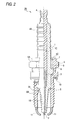
- Fig. 2 is a partial cross section view of a spark plug 20 used in the present invention.
- a battery 31 is connected to the primary of an ignition coil 34 at one end, with the other end of the primary being grounded via an igniter 33.
- the igniter 33 is connected to and controlled by an engine control computer unit (ECU) 32.
- the secondary of the ignition coil 34 is grounded at the negative terminal, not at the usual positive terminal.
- the positive terminal of the secondary is connected to a spark plug 20 via a high-voltage withstanding cable 35.
- the spark plug 20 may be according to any one of the first to fourteenth embodiments described below.
- the engine control computer unit (ECU) 32 sends appropriately timed pulse signals to the igniter 33 so that a current flows through the primary of the ignition coil 34 for a few milliseconds and then stops flowing. As a result, a high positive voltage develops at the positive terminal of the secondary of the ignition coil 34.
- the generated high positive voltage passes through the cable 35 to be impressed on the central electrode 2 of the spark plug 20, whereupon the air insulation between the central electrode 2 and the ground 11 is disrupted to produce a spark discharge which, in turn, causes a discharge current to flow in the direction indicated by arrow 101.
- the spark discharge described above is of positive polarity, the spark plug allows the central electrode 2 to wear very slowly and it has high durability.
- a porcelain insulator 1 typically made of alumina or other ceramics has a corrugation 1A in the upper part for ensuring an adequate creep distance and a leg portion 1B in the lower part that is to be exposed in the combustion chamber of an internal combustion engine.
- a center through-hole 1C extends through the center of the shaft.
- a central electrode 2 made of a nickel alloy such as Inconel is retained at the bottom end (distal end) of the center through-hole 1C such that it projects downward from the bottom end face of the porcelain insulator 1.
- the central electrode 2 is not solely composed of Inconel but has a core of copper (cu) fitted into the center with a view to providing better heat conductivity.
- the copper core is not shown in Fig. 2 to avoid complexity.
- the central electrode 2 is electrically connected to an upper terminal 4 via a glass resistor 3 provided within the center through-hole 1C.
- a high-voltage withstanding cable (not shown) is connected to the terminal 4 and high voltage is applied through the cable.
- the porcelain insulator 1 is supported within the main metallic shell 5.
- the main metallic shell 5 is made of a low-carbon steel material and has a hexagonal portion 5A that engages a spark plug wrench and a thread portion 5B which can be threaded into a cylinder head.
- the main metallic shell 5 also has a clamp portion 5C on which the main metallic shell 5 is clamped to become integral with the porcelain insulator 1.
- a sheet of packing member 6 is provided between a recessed step 5E in the main metallic shell 5 and the porcelain insulator 1, whereby the leg portion 1B to be exposed in the combustion chamber is completely isolated from the upper part of the porcelain insulator 1.
- Wires of seal member 7 and 8 are provided between the clamp portion 5C and the porcelain insulator 1 and the powder of talc 9 is packed between the two seal members 7 and 8 so that it works as an elastic sealant to ensure that the porcelain insulator 1 is completely secured to the main metallic shell 5. Needless to say, the talc 9 may be omitted to produce a talc-free spark plug.
- a gasket 10 is squeezed at the top end of the thread portion 5B.
- Two ground electrodes 11 made of a nickel alloy are welded to the bottom end of the main metallic shell 5. Each of the ground electrodes 11 is so formed that its mating end face is opposed to the peripheral side of the central electrode 2.
- Fig. 3 is a sectional view showing enlarged the distal end portion of a spark plug used in the ignition system according to the first embodiment of the invention.
- the tip of the spark plug shown at the bottom of Fig. 2 is inverted in Fig. 3 and shown at the top. That part of the central electrode 2 which is just above the porcelain insulator 1 is tapered so that its distal end portion has a smaller diameter.
- the entire part of the central electrode 2 that lies above the porcelain insulator 1 is not reduced in diameter but instead the base is thicker than the distal end portion; this is in order to ensure that the heat generated on the central electrode 2 is effectively dissipated to prevent its distal end portion from becoming overheated.
- a spark wear resistant member 21 in platinum (Pt) is laser welded to the peripheral side of the smaller-diameter, distal end portion of the central electrode 2.
- the two ground electrodes 11 are positioned diametrically to each other and project from the end face of the main metallic shell 5 toward their distal end.
- the distal end portion of each ground electrode 11 is bent by 90 degrees such that its mating end face 11A is opposed to the peripheral side of the central electrode 2.
- the spark wear resistant member 21 provided on the smaller-diameter portion of the central electrode 2 covers a comparatively wide area such that the edge of its lower end is positioned at the rear side (downward in Fig. 3) in comparison with the position corresponding to the edge on the rear side (down in Fig. 3) of the end face 11A of each ground electrode 11.
- the smaller-diameter portion at the distal end of the central electrode 2 has diameter A which takes either one of these five values: 0.6 (in millimeters, which applies in the following description of dimensions), 1.2, 1.8, 2.0 and 2.5. Thus, five samples of spark plug are provided.
- the smaller-diameter portion of the central electrode 2 has length B which is 2.5; the tapered portion has length C which is 1.0; the porcelain insulator 1 projects from the main metallic shell 5 by length D which is 2.5.
- each ground electrode 11 has a rectangular cross section with a thickness E of 1.6 and a width W (not shown) of 2.7; each ground electrode 11 projects from the main metallic shell 5 by length F which is 6.0. Hence, the most distal end of the central electrode 2 coincides in position with the edge on the front side of each ground electrode 11.
- the air gap G between the peripheral side of the central electrode 2 and the end face 11A of each ground electrode 11 is adjusted to have a setting of 1.1.
- the thread portion 5B of the main metallic shell 5 has a standard diameter M14S.
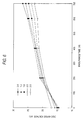
- Fig. 4 is a graph showing the gap wear that occurred in the five spark plug samples when high negative voltage was applied to the central electrode in the usual manner.
- the horizontal axis of the graph plots the endurance test time (in hours) and the vertical axis plots the amount of gap wear (in millimeters, representing the increase in the air gap G).
- the spark plug samples of the invention referred to by the solid symbols ⁇ , ⁇ and ⁇ experienced a markedly accelerated gap wear after the passage of 400 h and at the end of the test (700 h later), the gap wear was very different from the values for the samples using thick central electrodes that are referred to by the open symbols. It is therefore concluded that the spark plugs using thin central electrodes with diameter A being 1.8 mm or smaller are not suitable for commercial operation at negative polarity on account of the excessive gap wear.
- Fig. 5 is a graph showing the gap wear that occurred in the five spark plug samples when high positive voltage was applied to the central electrode.
- the designations of the horizontal and vertical axes are the same as defined for Fig. 4.
- the values of gap wear did not vary greatly with the diameter A of the central electrode and as the endurance test time increased, the gap wear increased at generally the same rate in the five spark plug samples.
- the general tendency remained the same and the gap wear increased with the decreasing diameter of the central electrode; however, the difference was small and the gap wear was no more than 0.2 mm in the five test samples. It is therefore concluded that even the spark plugs using thin central electrodes with diameter A being 1.8 mm or smaller experience less gap wear to be capable of operating with greater durability if positive, not negative, voltage is applied to the central electrode.
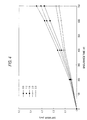
- Fig. 6 is a graph showing the change in discharge voltage that occurred in the five spark plug samples when they were operated with negative polarity in the usual manner.
- the discharge voltage was measured in terms of the instantaneous value that occurred during "idle racing" with the engine run under no load.
- the unit of discharge voltage measurement was kV (kilovolts).
- the discharge voltage decreased with the decreasing diameter A of the central electrode.
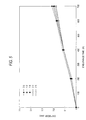
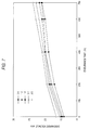
- Fig. 7 is a graph showing the change in discharge voltage that occurred when the five spark plug samples were operated with positive polarity.
- the designations of the horizontal and vertical axes were the same as defined for Fig. 6.
- the characteristics of the virgin state (the discharge voltage decreases with the decreasing diameter A of the central electrode) were maintained after the passage of 700 h of driving and the reversal of the tendency (see Fig. 6) was absent.
- the discharge voltage increased with the increasing time of endurance test but at a relatively slow rate. Even at the end of the test (after the passage of 700 h), the spark plugs using thin central electrodes with small values of diameter A required lower discharge voltages than the samples using large values of diameter A.
- the spark plugs of the invention that were operated with positive polarity, rather than the normal negative polarity, using thin central electrodes with diameter A being 1.8 mm or less could maintain relatively low discharge voltages. This demonstrates the improved durability of the spark plugs.
- the spark plug was operated with the positive polarity, so that the temperature of the central electrode can be lowered in comparison with that of the conventional spark plug operated with the negative polarity. This is one of factors for surprising to consume the central electrode and increase the discharge voltage.
- Table 2 shows the air fuel ratio (A/F) of the ignition limitation before and after the 700h endurance tests as described above.
- the air fuel ratio (A/F) which becomes the ignition limitation, is an air fuel ratio (A/F) where misfire ratio becomes 1%.
- An in-line, 6-cylinder, 2-L engine was used, and the measurement was performed at idling operation of 700ppm. Simultaneously, the spark jump positions of the central electrode 2 and the ground electrode 11 were confirmed.
- the spark jump ratio is a ratio of a case where the spark jump was generated between the central electrode and the distal end side of the ground electrode. Ignition limitation Positive polarity Negative polarity Air fuel ratio Spark jump ratio (%) Air fuel ratio Spark jump ratio (%) Before endurance test 17.2 100 16.8 90 After test endurance test 17.3 100 16.5 60
- the air fuel ratio (A/F) which becomes the ignition limitation, is an air fuel ratio (A/F) where a misfire ratio becomes 1%.
- An in-line, 6-cylinder, 2-L, lean burn engine was used, and the measurement was performed at an engine operation condition corresponding to 60km/h. Ignition limitation air fuel ratio Direction A 22.6 Direction B 21.6
- the direction A in which the ground electrode is positioned in vertical to the swirl, further improves the ignitability. This is because the following reasons.
- An air fuel mixture forms the swirl in a combustion chamber.
- the spark jumping between the electrodes of the spark plug contacts with the air fuel mixture moved by the swirl, so that the air fuel mixture is ignited and burned.
- the ground electrode if the ground electrode is positioned to be parallel to the swirl, the ground electrodes shields against the flow direction of the swirl, so that the air fuel mixture is hard to contact with the spark. Further, flame kernel generated between a gap abuts the electrode. Thus, the heat drawing by the electrode occurs to thereby obstruct the growth of the flame kernel.
- the ground electrode is vertical to the swirl, the ground electrode does not shield the flow of the swirl, thereby improving the ignitability.
- the swirl direction in the spark plug position is almost the same direction from low speed to high speed. Accordingly, if the direction of the ground electrode is set to be vertical to the swirl in one condition, good ignitability can be exhibited from low speed to high speed.
- Fig. 8 is a sectional view showing enlarged the distal end portion of a spark plug used in the ignition system according to the second embodiment of the invention.
- the two ground electrodes 11 made of 95% of Ni are positioned diametrically to each other and the mating surface 11A of each ground electrode 11 is opposed to the peripheral side of the central electrode 2.
- Each ground electrode 11 is disposed such that the rear edge of the end face 11A (downward in Fig. 8) is disposed in the side of the distal end (upward in Fig. 8) in comparison with the end face of the porcelain insulator 1.
- the shortest distance L from the end face 11A of the ground electrode 11 to the porcelain insulator 1 is adjusted to be smaller than the shortest distance G from the end face 11A of the ground electrode 11 to the peripheral side of the central electrode 2.
- the central electrode 2 has diameter A which takes the value 2.0 (in millimeters, which applies in the following description of dimensions) and it projects from the porcelain insulator 1 by length H which is either 1.8 or 2.2. Thus, two samples of spark plug are provided.
- the end face of the porcelain insulator 1 has a diameter K of 4.6. The distance J from the end face of the porcelain insulator 1 to the foremost edge (upward in Fig.
- the distal end 11A of the ground electrode 11 (J is hereunder referred to as the amount of projection J of the ground electrode) is set at 2.1; the thickness E of the ground electrode 11 (or the distance from the upper edge of the end face 11A to its lower edge) is set at 1.6; the distance L from the lower edge of the end face 11A of the ground electrode 11 to the end face of the porcelain insulator 1 (L is hereunder referred to as the semi-creep discharge air gap L) is set at 0.5; the distance G from the end face 11A of the ground electrode 11 to the peripheral side of the central electrode 2 (is hereunder referred to as the side electrode air gap G) is set at 1.3.
- the spark plug of the embodiment under consideration has a plurality of ground electrodes 11, with the end face 11A of each ground electrode 11 being opposed to the peripheral side of the central electrode 2.
- Table 4 Polarity of central central electrode Amount of central electrode electrode projection (H) Amount of ground electrode electrode projection (J) Spark jump at the tip of central electrode Spark jump in semi-creep surface discharge during smothering - 2.2 mm 2.1 mm 30% 100% + 2.2 mm 2.1 mm 70% 100% + 1.8 mm 2.1 mm 100% 100% 100%
- the efficiency of spark plug firing is correspondingly improved; at the same time, the occurrence of semi-creep discharge (spark runs along the end face of the porcelain insulator 1) is sufficiently suppressed to reduce the probability that the surface of the porcelain insulator is grooved by channeling. In other words, the spark plug has high resistance to channeling.
- the anti-fouling performance of the spark plug was evaluated by a so-called "pre-delivery fouling test". During its delivery from the assembly plant to a dealer, a car is driven many times for a very short distance each and the temperature of the spark plug remains at low level; therefore, the spark plug "smothers" and its insulation resistance decreases. This phenomenon is commonly called “pre-delivery fouling”.
- Diameter A of central electrode Rating 0.6 mm o ⁇ 1.0 mm o ⁇ 1.2 mm o ⁇ 1.6 mm ⁇ 1.8 mm ⁇ 2.0 mm ⁇ 2.2 mm ⁇ 2.4 mm X
- the respective criteria for rating shown in Table 5 have the following definitions: o ⁇ , more than 20 cycles were required for the insulation resistance to drop to 10 M ⁇ ; ⁇ , 10 - 20 cycles were required; ⁇ , 5 - 10 cycles were required; X, the insulation resistance dropped below 10 M ⁇ in less than 5 cycles.
- the fouling resistance of the spark plug increases with decreasing diameter A of the central electrode 2.
- the diameter A of the central electrode 2 is preferably 2 mm or less, more preferably, 1.2 mm or less.
- Fig. 9 is a graph showing the result of an experiment conducted to investigate the anti-channeling performance of the contemplated spark plug of the invention in terms of the relationship between the semi-creep discharge air gap L and the side electrode air gap G.
- the horizontal axis of the graph plots the semi-creep discharge air gap F and the vertical axis plots the side electrode air gap G.
- the symbols ( o ⁇ , ⁇ , ⁇ ) in the graph represent the degree of channeling.
- the semi-creep discharge air gap L was adjusted to have one of the following three values, 0.3 mm, 0.45 mm and 0.6 mm, whereas the side electrode air gap G was adjusted to have one of five values between 1.0 mm and 1.4 mm; thus, a total of eleven spark plug samples were prepared.
- each ground electrode 11 Since the thickness E of each ground electrode 11 was 1.6 mm, the amount of its projection J took the value 1.9 mm, 2.05 mm or 2.2 mm depending on the size of the semi-creep discharge air gap L. The foremost end of the central electrode 2 was adjusted to coincide in position with the front edge of the end face 11A of each ground electrode 11.
- the central electrode 2 was connected to a positive terminal and high voltage with a peak of about 20 kV was applied intermittently for 500 h at a frequency of 60 Hz.
- the depth of the channeling groove in the surface of the porcelain insulator 1 was examined and measured with a scanning electron microscope. This experiment measured the degree of channeling due to the spark jumps along the end face of the porcelain insulator 1 that made no contribution to the spark cleaning of carbon fouling.
- Fig. 9 The results of the experiment are shown in Fig. 9 by rating according to the following criteria: o ⁇ , slight with the channeling groove depth being less than 0.2 mm; ⁇ , moderate with groove depth of 0.2 - 0.4 mm; ⁇ , extensive with groove depth in excess of 0.4 mm.
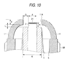
- Fig. 10 shows in section the distal end portion of a spark plug of the third embodiment used in the ignition system according to the present invention.
- a spark wear resistant member 21 in the form of a Pt disk is resistance welded to the tip of the central electrode 2 made of Inconel (trademark).
- the diameter A of the central electrode 2 is 2.0; the diameter K of the end face of the porcelain insulator 1 is 4.6; the thickness E of each ground electrode 11 made of 95wt% of Ni is 1.6; the semi-creep discharge air gap L is 0.5; the side electrode air gap G is 1.3.
- the amount of projection H of the central electrode 2 is smaller than the value adopted in the second embodiment and takes 0.3, 0.5 or 1.0. Hence, three samples of spark plug were prepared for testing.
- Fig. 11 is a graph showing the results of an on-board endurance test on the three spark plug samples.
- the horizontal axis of the graph plots time and the vertical axis plots the gap wear or the increase in the side electrode air gap G.
- WOT full throttle
- Fig. 12 shows in section the distal end portion of a spark plug of the fourth embodiment used in the ignition system according to the present invention.
- a chip of spark wear resistant member 22 in the form of a Pt disk is laser welded to two areas of the small-diameter portion that are opposed to the end faces 11A of the ground electrodes 11 where most of the spark jumps are likely to occur.
- This fourth embodiment has the advantage of using a smaller amount of the expensive spark wear resistant member.
- Fig. 13 shows in section the distal end portion of a spark plug of the fifth embodiment used in the ignition system according to the present invention.
- a chip of spark wear resistant member 23 in the form of a Pt cylinder is laser welded to the distal end of the smaller-diameter portion of a central electrode body 2 made of Inconel, thereby making the central electrode.
- the most distal end of the chip 23 is located between the front and rear edges of the end face 11A of each ground electrode 11.
- This fifth embodiment of the invention has the advantage of not only retarding the wear of the central electrode but also making the smaller-diameter portion 23 of the central electrode even thinner to achieve a further decrease in the discharge voltage. As an additional advantage, the efficiency of spark jumping at the tip of the central electrode is enhanced to provide more efficient firing.
- Fig. 14 shows in section the distal end portion of a spark plug of the sixth embodiment used in the ignition system according to the present invention.
- a chip of spark wear resistant member 24 in platinum that consists of an upper, smaller-diameter cylinder and a lower, larger-diameter cylinder is resistance welded to the tip of a central electrode body 2 made of Inconel having an even larger diameter, thereby making the central electrode.
- the smaller-diameter portion of the chip 24 provides a jump sparking tip.
- the most distal end of the chip 24 is located between the front and rear edges of the end face 11A of each ground electrode 11.
- This sixth embodiment of the present invention has the advantage of ease in manufacture since there is no need to reduce the diameter of a selected area of the central electrode body 2.
- Fig. 15 shows in section the distal end portion of a spark plug used for the ignition system according to the seventh embodiment of the present invention.
- a chip of spark wear resistant member 25 in the form of a Pt cylinder is laser welded to the distal end of the smaller-diameter portion of a central electrode body 2 made of Inconel, thereby making the central electrode.
- the most distal end of the chip 25 is located between the front and rear edges of the end face 11A of each ground electrode 11.
- a rectangular sheet of spark wear resistant member 26 is resistance welded to the mating end faces of the ground electrodes 11.
- Fig. 16 shows in section the distal end portion of a spark plug used for the ignition system according to the eighth embodiment of the present invention, in which the concept of the invention is applied to spark plugs of small diameters such as M10S and M8S.
- a chip of spark wear resistant member 27 in the form of a Pt cylinder is laser welded to the distal end of the smaller-diameter portion of a central electrode body 2 made of Inconel, thereby making the central electrode.
- the diameter A of chip 27 is 0.8 mm; the thickness E of the end face 11A of each ground electrode 11 is 1.1 mm and its width W (not shown) is 2.2 mm. With such small-diameter spark plugs, the outside ground electrodes 11 cannot have an adequate cross-sectional area.
- the diameter of the distal end portion of the central electrode 2 and, hence, its projection from the porcelain insulator 1 can be reduced; as a result, the projection of the ground electrodes 11 from the main metallic shell 5 is sufficiently reduced to ensure that they have an adequate strength for practical purposes.
- Fig. 17 shows in section the distal end portion of a spark plug used for an ignition system according to the ninth embodiment of the present invention, in which the concept of the present invention is applied to spark plugs of an intermittent, semi-creep discharge type.
- a chip of spark wear resistant member 28 in the form of a Pt cylinder is laser welded to the distal end of the smaller-diameter portion of a central electrode body 2 made of Inconel, thereby making the central electrode.
- Two outside ground electrodes 11 made of 95wt% of Ni are provided in such a way that their end faces 11A are opposed to the peripheral side of the chip 28, with the edge of the rear end (downward in Fig. 17) of each end face 11A is reasonably close to the end face of the porcelain insulator 1.
- the spark plug according to the ninth embodiment of the present invention has an effective anti-fouling property. It also retains the essential features of the invention, i.e., the small diameter of the distal end 28 of the central electrode, efficient firing, and high durability.
- Fig. 18 shows in section the distal end portion of a spark plug used for the ignition system according to the tenth embodiment of the present invention.
- a spark wear resistant member 29 in the form of a Pt disk is laser welded not to the tip surface but the peripheral side of the central electrode 2 made of 95wt% of Ni.
- the spark wear resistant member 29 extends to the foremost end of the central electrode 2.
- the dimensions of the respective parts shown in Fig. 18 are generally the same as in the first embodiment.
- the spark plug used at positive polarity has an improved ratio of spark jumps in the distal end portion of the central electrode 2, making it practically suitable for use as an intermittent semi-creep discharge spark plug having high resistance to channeling.
- the spark wear resistant member 29 fitted in the distal end portion of the central electrode 2 increases the durability of the spark plug.
- Fig. 19 shows in section the distal end portion of a spark plug used for the ignition system according to the eleventh embodiment of the present invention.
- the central electrode body 2 made of Inconel is reduced in diameter in the portion that projects from the porcelain insulator 1.
- a chip of spark wear resistant member 201 in the form of a Pt cylinder is resistance welded to the distal end of the reduced-diameter portion of the central electrode body 2, whereby the central electrode is made up of the chip 201 and the central electrode body 2.
- the foremost end of the central electrode (the distal end of the chip 201) is located between the front and rear edges of the end face 11A of each ground electrode 11.
- the distal end portion of the central electrode can be reduced in diameter without sacrificing the overall strength of the central electrode and the reduced diameter contributes to enhance the anti-fouling property of the spark plug by increasing the efficiency of spark cleaning during creep discharge.
- the Pt chip 201 fitted in the distal end portion of the central electrode contributes to reduce spark wear.
- Fig. 20 shows in section the distal end portion of a spark plug used for the ignition system according to the twelfth embodiment of the present invention.
- the end face 11A of the ground electrode 11 obliquely opposes to the peripheral side face of the central electrode 2 having no spark wear resistant member.
- the shortest distance G from the end edge 11B at the bottom side of the drawing of the end face 11A of the ground electrode 11 to the peripheral side face of the central electrode 2 is formed to be 1.5 times or more than the shortest distance L from the ground electrode 11 to the porcelain insulator 1.
- the diameter K of the end face of the porcelain insulator 1 is 4.6; the thickness E of the ground electrode 11 made of 95wt% of Ni is 1.6; the semi-creep discharge air gap L is 0.5; and the side electrode air discharge gap G is 1.5.
- the central electrode 2 is formed of 95wt% of Ni. Other elements are similar to those of the third embodiment.
- Fig. 21 shows in section the distal end portion of a spark plug used for the ignition system according to the thirteenth embodiment of the present invention.
- a central electrode body 2 made of Inconel (trademark) is recessed into a porcelain insulator 1.
- a spark wear resistant member 202 in the form of a Pt cylinder is resistance welded to the tip surface of the recessed central electrode body 2.
- the cylindrical member 202 consists of an upper small-diameter portion and a lower large-diameter portion.
- the tip surface of the small-diameter portion of the cylindrical member 202 is located between the front and rear edges of the end face 11A of each ground electrode 11 made of 95wt% of nickel.
- the central electrode body 2 and the spark wear resistant member 202 combine to form the central electrode. This design provides relative ease in fabricating a central electrode that has a thin, spark jumping portion and which yet has high spark resistance.
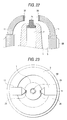
- Fig. 22 shows in section the distal end portion of a spark plug used for the ignition system according to the fourteenth embodiment of the present invention.
- a central electrode body 2 made of Inconel (trademark) is recessed in a porcelain insulator 1.
- a spark wear resistant member 203 in the form of a Pt cylinder is resistance welded to the tip surface of the recessed central electrode body 2.
- the cylindrical member 203 consists of an upper small-diameter portion and a lower large-diameter portion.
- the end face portion of the porcelain insulator 1 is so formed as to conceal the central electrode body 2 and the lower large-diameter portion of the cylindrical spark wear resistant member 203.
- the small-diameter distal end portion of the spark wear resistant member 203 projects from the end face of the porcelain insulator 1 such that its tip surface is located between the front and rear edges of the end face of each ground electrode 11 made of Inconel (trademark).
- the central electrode body 2 combines with the spark wear resistant member 203 to form the central electrode.
- Fig. 23 is a plan view of the distal end portion of the spark plug used for the ignition system according to the fourteenth embodiment of the present invention which is shown in Fig. 22.
- the distal end of each ground electrode 11 is tapered like a wedge and a prismatic spark wear resistant member 204 made of Pt is secured to the tip.
- the spark wear resistant member 204 on each ground electrode is opposed to the peripheral side of the spark wear resistant member 203 serving as part of the central electrode.
- the central electrode and each ground electrode have the spark wear resistant members 203 and 204, respectively, in the spark jumping portion; thus, both the spark jumping portion 203 of the central electrode and the spark jumping portion 204 of each ground electrode have sufficient spark wear resistance to increase the durability of the spark plug.
- the end face of the porcelain insulator 1 has a larger area than the spark plug according to the thirteenth embodiment shown in Fig. 21 and, hence, the spark plug of the fourteenth embodiment has higher resistance to fouling.
Landscapes
- Spark Plugs (AREA)
Applications Claiming Priority (4)
| Application Number | Priority Date | Filing Date | Title |
|---|---|---|---|
| JP31766398 | 1998-11-09 | ||
| JP31766398 | 1998-11-09 | ||
| JP33275098 | 1998-11-24 | ||
| JP33275098 | 1998-11-24 |
Publications (3)
| Publication Number | Publication Date |
|---|---|
| EP1001502A2 true EP1001502A2 (fr) | 2000-05-17 |
| EP1001502A3 EP1001502A3 (fr) | 2001-12-12 |
| EP1001502B1 EP1001502B1 (fr) | 2005-10-26 |
Family
ID=26569095
Family Applications (1)
| Application Number | Title | Priority Date | Filing Date |
|---|---|---|---|
| EP99308929A Expired - Lifetime EP1001502B1 (fr) | 1998-11-09 | 1999-11-09 | Système d'allumage |
Country Status (3)
| Country | Link |
|---|---|
| US (1) | US6617706B2 (fr) |
| EP (1) | EP1001502B1 (fr) |
| DE (1) | DE69927906T2 (fr) |
Cited By (5)
| Publication number | Priority date | Publication date | Assignee | Title |
|---|---|---|---|---|
| EP1231687A2 (fr) | 2001-02-13 | 2002-08-14 | Denso Corporation | Bougie d'allumage et allumage muni de celle-ci |
| GB2373294A (en) * | 2001-02-13 | 2002-09-18 | Denso Corp | A spark plug with provision for self cleaning and a wear resisting member on the centre electrode |
| EP1895121A3 (fr) * | 2006-06-29 | 2008-05-28 | Byoung Pyo Jun | Dispositif de promotion de combustion pour moteur à combustion interne |
| EP2073328A3 (fr) * | 2007-12-19 | 2013-01-02 | Ngk Spark Plug Co., Ltd | Bougie d'allumage |
| CN104061107B (zh) * | 2013-03-14 | 2017-07-18 | 博格华纳贝鲁系统有限公司 | 电晕点火装置 |
Families Citing this family (7)
| Publication number | Priority date | Publication date | Assignee | Title |
|---|---|---|---|---|
| JP4322458B2 (ja) * | 2001-02-13 | 2009-09-02 | 株式会社日本自動車部品総合研究所 | 点火装置 |
| US7288879B2 (en) * | 2004-09-01 | 2007-10-30 | Ngk Spark Plug Co., Ltd. | Spark plug having ground electrode including precious metal alloy portion containing first, second and third components |
| DE102005006354A1 (de) * | 2005-02-11 | 2006-08-24 | Robert Bosch Gmbh | Zündanlage für eine Brennkraftmaschine |
| US7588021B2 (en) * | 2006-04-14 | 2009-09-15 | Federal-Mogul Worldwide, Inc | Spark plug circuit |
| EP2278671B1 (fr) * | 2008-04-23 | 2019-02-27 | NGK Spark Plug Co., Ltd. | Procédé de fabrication d'une bougie d'allumage |
| CN103828149B (zh) | 2011-08-19 | 2016-05-04 | 费德罗-莫格尔点火公司 | 包括温度控制结构的电晕点火器 |
| US10054100B2 (en) * | 2016-02-09 | 2018-08-21 | Miyama, Inc. | Multipoint spark plug and multipoint ignition engine |
Family Cites Families (25)
| Publication number | Priority date | Publication date | Assignee | Title |
|---|---|---|---|---|
| JPS5432620A (en) | 1977-08-16 | 1979-03-10 | Katsuraya Fine Goods | Insecticidal agent |
| JPS5972689A (ja) | 1982-10-19 | 1984-04-24 | Pioneer Electronic Corp | プログラムローディング方法 |
| JPS60220586A (ja) | 1984-04-16 | 1985-11-05 | 日本特殊陶業株式会社 | 小型スパ−クプラグ |
| JPS60232679A (ja) | 1984-04-28 | 1985-11-19 | 日本特殊陶業株式会社 | スパ−クプラグ |
| JP3010234B2 (ja) * | 1990-08-08 | 2000-02-21 | 日本特殊陶業株式会社 | 外側電極を多極化したスパークプラグ |
| JP2566702B2 (ja) | 1991-09-02 | 1996-12-25 | 日本特殊陶業株式会社 | ガソリン機関の失火検出装置 |
| JPH05335066A (ja) * | 1992-06-01 | 1993-12-17 | Nippondenso Co Ltd | 内燃機関用スパークプラグ |
| JP3254760B2 (ja) | 1992-10-26 | 2002-02-12 | 株式会社デンソー | 内燃機関用スパークプラグ |
| JPH06176849A (ja) | 1992-12-10 | 1994-06-24 | Ngk Spark Plug Co Ltd | セミ沿面放電型内燃機関用スパークプラグ |
| JP3315462B2 (ja) * | 1993-04-26 | 2002-08-19 | 日本特殊陶業株式会社 | スパークプラグ |
| JP3473044B2 (ja) * | 1993-04-28 | 2003-12-02 | 株式会社デンソー | スパークプラグ |
| JP3368635B2 (ja) * | 1993-11-05 | 2003-01-20 | 株式会社デンソー | スパ−クプラグ |
| JP3503075B2 (ja) | 1994-04-19 | 2004-03-02 | 日本特殊陶業株式会社 | 内燃機関用スパークプラグ |
| JP3675873B2 (ja) | 1995-02-09 | 2005-07-27 | 株式会社デンソー | 内燃機関用スパークプラグ |
| EP0758152B1 (fr) | 1995-08-09 | 2002-11-27 | Ngk Spark Plug Co., Ltd | Bougie d'allumage |
| JPH09106881A (ja) | 1995-08-09 | 1997-04-22 | Ngk Spark Plug Co Ltd | スパークプラグ |
| US5793151A (en) | 1995-09-20 | 1998-08-11 | Ngk Spark Plug Co., Ltd. | Creeping discharge spark plug |
| JP3272615B2 (ja) | 1995-11-16 | 2002-04-08 | 日本特殊陶業株式会社 | 内燃機関のスパークプラグ |
| JP3265210B2 (ja) | 1996-01-19 | 2002-03-11 | 日本特殊陶業株式会社 | スパークプラグ |
| JP3924041B2 (ja) | 1996-04-05 | 2007-06-06 | 日本特殊陶業株式会社 | 両極性電源イグニッションシステム |
| JPH09330782A (ja) * | 1996-06-07 | 1997-12-22 | Ngk Spark Plug Co Ltd | スパークプラグ |
| JP3874840B2 (ja) | 1996-06-10 | 2007-01-31 | 日本特殊陶業株式会社 | 多極スパークプラグ |
| JP3297636B2 (ja) * | 1997-03-07 | 2002-07-02 | 日本特殊陶業株式会社 | セミ沿面放電形のスパークプラグ |
| GB2327459A (en) | 1997-07-17 | 1999-01-27 | Dawson Royalties Ltd | Spark plug for i.c. engines |
| JP3269032B2 (ja) * | 1997-09-01 | 2002-03-25 | 日本特殊陶業株式会社 | スパークプラグ及びそれを用いた内燃機関用点火システム |
-
1999
- 1999-11-08 US US09/435,368 patent/US6617706B2/en not_active Expired - Fee Related
- 1999-11-09 EP EP99308929A patent/EP1001502B1/fr not_active Expired - Lifetime
- 1999-11-09 DE DE69927906T patent/DE69927906T2/de not_active Expired - Lifetime
Cited By (7)
| Publication number | Priority date | Publication date | Assignee | Title |
|---|---|---|---|---|
| EP1231687A2 (fr) | 2001-02-13 | 2002-08-14 | Denso Corporation | Bougie d'allumage et allumage muni de celle-ci |
| GB2373294A (en) * | 2001-02-13 | 2002-09-18 | Denso Corp | A spark plug with provision for self cleaning and a wear resisting member on the centre electrode |
| GB2373294B (en) * | 2001-02-13 | 2005-02-02 | Denso Corp | A self-cleaning spark plug with a wear resisting member on the centre electrode |
| US6956319B2 (en) | 2001-02-13 | 2005-10-18 | Denso Corporation | Structure of spark plug designed to provide higher wear resistance to center electrode and production method thereof |
| EP1895121A3 (fr) * | 2006-06-29 | 2008-05-28 | Byoung Pyo Jun | Dispositif de promotion de combustion pour moteur à combustion interne |
| EP2073328A3 (fr) * | 2007-12-19 | 2013-01-02 | Ngk Spark Plug Co., Ltd | Bougie d'allumage |
| CN104061107B (zh) * | 2013-03-14 | 2017-07-18 | 博格华纳贝鲁系统有限公司 | 电晕点火装置 |
Also Published As
| Publication number | Publication date |
|---|---|
| US20020167225A1 (en) | 2002-11-14 |
| DE69927906D1 (de) | 2005-12-01 |
| DE69927906T2 (de) | 2006-07-20 |
| EP1001502B1 (fr) | 2005-10-26 |
| EP1001502A3 (fr) | 2001-12-12 |
| US6617706B2 (en) | 2003-09-09 |
Similar Documents
| Publication | Publication Date | Title |
|---|---|---|
| CA2246172C (fr) | Bougie d'allumage et moteur a combustion interne utilisant celle-ci | |
| EP1001502B1 (fr) | Système d'allumage | |
| US6229253B1 (en) | Spark plug with specific gap between insulator and electrodes | |
| CN110867729B (zh) | 火花塞 | |
| US8853926B2 (en) | Spark plug with firing end having downward extending tines | |
| US6225752B1 (en) | Spark plug for internal combustion engine | |
| US6611084B2 (en) | Spark plug | |
| GB2225385A (en) | Spark plug electrodes | |
| JP4270784B2 (ja) | スパークプラグ | |
| US7122948B2 (en) | Spark plug having enhanced capability to ignite air-fuel mixture | |
| EP0989645B1 (fr) | Bougie d'allumage | |
| JP2001093645A (ja) | 内燃機関用スパークプラグ | |
| EP0376147B1 (fr) | Bougies d'allumage pour moteurs à combustion interne | |
| US1989670A (en) | Spark plug | |
| JP2000223239A (ja) | スパ―クプラグ及びそのスパ―クプラグを用いた点火システム | |
| CN206506154U (zh) | 一种火花塞 | |
| JP2000208234A (ja) | スパ―クプラグ及びそのスパ―クプラグを用いた点火システム | |
| JP2002270332A (ja) | スパークプラグ | |
| JP4398483B2 (ja) | スパークプラグ | |
| JP4532009B2 (ja) | スパークプラグ | |
| US6078130A (en) | Spark plug with specific construction to avoid unwanted surface discharge | |
| JP3589693B2 (ja) | スパークプラグ | |
| US5847492A (en) | Spark Plug | |
| KR101749685B1 (ko) | 점화 플러그 | |
| JPH0737675A (ja) | 内燃機関用スパークプラグ |
Legal Events
| Date | Code | Title | Description |
|---|---|---|---|
| PUAI | Public reference made under article 153(3) epc to a published international application that has entered the european phase |
Free format text: ORIGINAL CODE: 0009012 |
|
| AK | Designated contracting states |
Kind code of ref document: A2 Designated state(s): AT BE CH CY DE DK ES FI FR GB GR IE IT LI LU MC NL PT SE Kind code of ref document: A2 Designated state(s): DE FR GB IT |
|
| AX | Request for extension of the european patent |
Free format text: AL;LT;LV;MK;RO;SI |
|
| PUAL | Search report despatched |
Free format text: ORIGINAL CODE: 0009013 |
|
| AK | Designated contracting states |
Kind code of ref document: A3 Designated state(s): AT BE CH CY DE DK ES FI FR GB GR IE IT LI LU MC NL PT SE |
|
| AX | Request for extension of the european patent |
Free format text: AL;LT;LV;MK;RO;SI |
|
| RIC1 | Information provided on ipc code assigned before grant |
Free format text: 7H 01T 13/39 A, 7H 01T 13/46 B |
|
| 17P | Request for examination filed |
Effective date: 20020611 |
|
| AKX | Designation fees paid |
Free format text: DE FR GB IT |
|
| 17Q | First examination report despatched |
Effective date: 20030909 |
|
| GRAP | Despatch of communication of intention to grant a patent |
Free format text: ORIGINAL CODE: EPIDOSNIGR1 |
|
| GRAS | Grant fee paid |
Free format text: ORIGINAL CODE: EPIDOSNIGR3 |
|
| GRAA | (expected) grant |
Free format text: ORIGINAL CODE: 0009210 |
|
| AK | Designated contracting states |
Kind code of ref document: B1 Designated state(s): DE FR GB IT |
|
| REG | Reference to a national code |
Ref country code: GB Ref legal event code: FG4D |
|
| REF | Corresponds to: |
Ref document number: 69927906 Country of ref document: DE Date of ref document: 20051201 Kind code of ref document: P |
|
| PG25 | Lapsed in a contracting state [announced via postgrant information from national office to epo] |
Ref country code: GB Free format text: LAPSE BECAUSE OF NON-PAYMENT OF DUE FEES Effective date: 20060126 |
|
| ET | Fr: translation filed | ||
| PLBE | No opposition filed within time limit |
Free format text: ORIGINAL CODE: 0009261 |
|
| STAA | Information on the status of an ep patent application or granted ep patent |
Free format text: STATUS: NO OPPOSITION FILED WITHIN TIME LIMIT |
|
| GBPC | Gb: european patent ceased through non-payment of renewal fee |
Effective date: 20060126 |
|
| 26N | No opposition filed |
Effective date: 20060727 |
|
| PGFP | Annual fee paid to national office [announced via postgrant information from national office to epo] |
Ref country code: IT Payment date: 20081126 Year of fee payment: 10 |
|
| PG25 | Lapsed in a contracting state [announced via postgrant information from national office to epo] |
Ref country code: IT Free format text: LAPSE BECAUSE OF NON-PAYMENT OF DUE FEES Effective date: 20091109 |
|
| REG | Reference to a national code |
Ref country code: FR Ref legal event code: PLFP Year of fee payment: 17 |
|
| PGFP | Annual fee paid to national office [announced via postgrant information from national office to epo] |
Ref country code: DE Payment date: 20151103 Year of fee payment: 17 |
|
| PGFP | Annual fee paid to national office [announced via postgrant information from national office to epo] |
Ref country code: FR Payment date: 20151008 Year of fee payment: 17 |
|
| REG | Reference to a national code |
Ref country code: DE Ref legal event code: R119 Ref document number: 69927906 Country of ref document: DE |
|
| REG | Reference to a national code |
Ref country code: FR Ref legal event code: ST Effective date: 20170731 |
|
| PG25 | Lapsed in a contracting state [announced via postgrant information from national office to epo] |
Ref country code: FR Free format text: LAPSE BECAUSE OF NON-PAYMENT OF DUE FEES Effective date: 20161130 |
|
| PG25 | Lapsed in a contracting state [announced via postgrant information from national office to epo] |
Ref country code: DE Free format text: LAPSE BECAUSE OF NON-PAYMENT OF DUE FEES Effective date: 20170601 |