EP1002497B1 - Blutgefäss Bilddarstellungssystem - Google Patents
Blutgefäss Bilddarstellungssystem Download PDFInfo
- Publication number
- EP1002497B1 EP1002497B1 EP99123025A EP99123025A EP1002497B1 EP 1002497 B1 EP1002497 B1 EP 1002497B1 EP 99123025 A EP99123025 A EP 99123025A EP 99123025 A EP99123025 A EP 99123025A EP 1002497 B1 EP1002497 B1 EP 1002497B1
- Authority
- EP
- European Patent Office
- Prior art keywords
- components
- organism
- intensity
- beat
- image signal
- Prior art date
- Legal status (The legal status is an assumption and is not a legal conclusion. Google has not performed a legal analysis and makes no representation as to the accuracy of the status listed.)
- Expired - Lifetime
Links
- 210000004204 blood vessel Anatomy 0.000 title claims description 37
- 238000003384 imaging method Methods 0.000 title description 15
- 238000001514 detection method Methods 0.000 claims description 56
- 238000001228 spectrum Methods 0.000 claims description 55
- 210000003462 vein Anatomy 0.000 claims description 40
- 230000003287 optical effect Effects 0.000 claims description 33
- 230000003595 spectral effect Effects 0.000 claims description 12
- 230000003993 interaction Effects 0.000 claims description 3
- 238000010183 spectrum analysis Methods 0.000 claims description 3
- 238000011144 upstream manufacturing Methods 0.000 claims description 2
- 230000008320 venous blood flow Effects 0.000 claims 5
- 230000008321 arterial blood flow Effects 0.000 claims 2
- 238000001914 filtration Methods 0.000 claims 2
- 210000001367 artery Anatomy 0.000 description 38
- 239000012530 fluid Substances 0.000 description 36
- 239000008280 blood Substances 0.000 description 28
- 210000004369 blood Anatomy 0.000 description 28
- 238000004458 analytical method Methods 0.000 description 12
- 230000005540 biological transmission Effects 0.000 description 7
- 238000000149 argon plasma sintering Methods 0.000 description 5
- 230000010349 pulsation Effects 0.000 description 5
- 238000000034 method Methods 0.000 description 3
- 206010003210 Arteriosclerosis Diseases 0.000 description 2
- 238000002583 angiography Methods 0.000 description 2
- 208000011775 arteriosclerosis disease Diseases 0.000 description 2
- 230000017531 blood circulation Effects 0.000 description 2
- 230000007423 decrease Effects 0.000 description 2
- 238000010521 absorption reaction Methods 0.000 description 1
- 230000001427 coherent effect Effects 0.000 description 1
- 230000001419 dependent effect Effects 0.000 description 1
- 238000003745 diagnosis Methods 0.000 description 1
- 239000004973 liquid crystal related substance Substances 0.000 description 1
- 238000005259 measurement Methods 0.000 description 1
- 230000035515 penetration Effects 0.000 description 1
- 230000002093 peripheral effect Effects 0.000 description 1
- 238000005070 sampling Methods 0.000 description 1
Images


Classifications
-
- A—HUMAN NECESSITIES
- A61—MEDICAL OR VETERINARY SCIENCE; HYGIENE
- A61B—DIAGNOSIS; SURGERY; IDENTIFICATION
- A61B5/00—Measuring for diagnostic purposes; Identification of persons
- A61B5/02—Detecting, measuring or recording for evaluating the cardiovascular system, e.g. pulse, heart rate, blood pressure or blood flow
- A61B5/026—Measuring blood flow
- A61B5/0261—Measuring blood flow using optical means, e.g. infrared light
Definitions
- This invention relates to a blood vessel distinguishing system.
- This invention provides a system, which can clearly distinguish arteries and veins from each other.
- arteriosclerosis In the clinical field, there has been a wide demand for imaging arteries and veins clearly distinguished from each other. For example, since arteriosclerosis generally starts at the periphery of the arteries, it will be useful in diagnosing arteriosclerosis if the inner walls of the peripheral arteries can be imaged distinguished from those of the veins.
- US-A-4,109,647 discloses a system for measurement of blood flow using the Doppler scattering of coherent light.
- the object of the present invention is to provide a blood vessel distinguishing system, which can image blood flow within arteries and veins clearly distinguished from each other without exposing the testee to heavy load.
- a blood vessel distinguishing system comprising the features of claim 1.
- the distinguishing means detects frequency components of the measuring light scattered by the organism, detects the half-width of the spectrum of the frequency detection signal and distinguishes an artery and a vein in the organism from each other on the basis of the half-width.
- the distinguishing means may be a means which detects frequency components of the measuring light scattered by the organism, detects the intensity of off-centered components in a frequency band deviated from the center frequency of the frequency detection signal by a predetermined width and distinguishes an artery and a vein in the organism from each other on the basis of the intensity.
- the distinguishing means may be a means which detects frequency components of the measuring light scattered by the organism, detects the ratio between the intensity of center frequency components of the frequency detection signal and the intensity of off-centered components in a frequency band deviated from the center frequency of the frequency detection signal by a predetermined width and distinguishes an artery and a vein in the organism from each other on the basis of the intensity ratio.
- the distinguishing means may be a means which detects frequency components of the measuring light scattered by the organism on the basis of an optical heterodyne detection signal.
- an optical heterodyne detection system is employed in order to ensure high spatial resolution to an organism as a scattering medium, and arteries and veins are distinguished from each other on the basis of the fact that the spectral broadening (Doppler broadening) of beat component detection signal output from the heterodyne detection system changes with the flow rate of blood in the blood vessel.
- Doppler broadening spectral broadening
- the image signal generating means generates an image signal representing artery parts of the organism on the basis of components of the off-centered beat signal which are higher than the predetermined threshold level, and generates an image signal representing vein parts of the organism on the basis of components of the off-centered beat signal which are lower than the predetermined threshold level.
- the system be provided with an in-phase time detecting means which detects in-phase times at which broadening of the spectrum of the beat component detection signal becomes of a predetermined phase, and a synchronization detecting means which samples the off-centered beat signal at the in-phase times and inputs the off-centered beat signal thus obtained into the image signal generating means.
- the in-phase time detecting means may be, for instance, a means for detecting the pulse wave of the organism, or a means for detecting the times at which the center frequency component of the beat component detection signal takes a predetermined peak value.
- the measuring light source comprises a linear or two-dimensional array of a plurality of light emitting portions and the optical heterodyne detection system is arranged to be able to detect in parallel beat components of the combined light beams based on the measuring light beams from the respective light emitting portions, and the measuring light source and the optical heterodyne detection system also function as at least a part of said scanning means.
- beat component detection signal (beat signal) output from the heterodyne detection system described above represents intensity of only straight light components traveling straight through the organism or scattered light components close to the straight light components except influence of scattering by the organism which is a scattering medium.
- Figure 4A shows a spectrum of the beat signal when the flow rate of the fluid is 0, and Figures 4B to 4D show those for different flow rates of the fluid which increase in this order.
- the peak value of the intensity of the beat signal becomes lower and the spectrum of the beat signal is broadened (Doppler broadening) as the flow rate of the fluid increases.
- blood is also a fluid which causes multiple scattering of light
- the same phenomenon occurs when the measuring light beam passes through a blood vessel. Since arterial blood is generally higher than venous blood in flow rate, the reduction in the peak value of the intensity of the beat signal and broadening of the spectrum are larger when the measuring light beam travels through an artery than when the measuring light beam travels through a vein.
- line a shows a spectrum of the beat signal when the measuring light beam travels through an artery
- line b shows a spectrum of the beat signal when the measuring light beam travels through a vein.
- the predetermined threshold value is set, for instance, at d in Figure 5
- an image signal is generated on the basis of components of the off-centered beat signal which are higher than the predetermined threshold level d
- an image signal representing only artery parts of the organism can be generated.
- an image signal is generated on the basis of components of the off-centered beat signal which are lower than the predetermined threshold level d
- an image signal representing only vein parts of the organism can be generated.
- a measuring light source comprising a linear or two-dimensional array of a plurality of light emitting portions and an optical heterodyne detection system which can detect in parallel beat components of the combined light beams based on the measuring light beams from the respective light emitting portions
- the measuring light source and the optical heterodyne detection system also function as at least a part of said scanning means, it becomes unnecessary for the scanning means to mechanically cause the measuring light beam to scan the organism in at least one direction, whereby the scanning speed, which results in the imaging speed, can be increased.
- This is especially advantageous in the case where the off-centered beat signal is sampled at said in-phase times and sampling of the off-centered beat signal requires a relatively long time.
- a blood vessel imaging system comprising
- the beat component detection signal (beat signal) output from the heterodyne detection system described above represents intensity of only straight light components traveling straight through the organism or scattered light components close to the straight light components except influence of scattering by the organism which is a scattering medium.
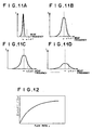
- Figure 11A shows a spectrum of the beat signal when the flow rate of the fluid is 0, and Figures 11B to 11D show those for different flow rates of the fluid which increase in this order.
- the peak value of the intensity of the beat signal becomes lower and the spectrum of the beat signal is broadened (Doppler broadening) as the flow rate of the fluid increases.
- the ratio I( ⁇ + ⁇ f)/I( ⁇ ), to the intensity I( ⁇ ) of the center frequency components of the beat signal (the components of the beat signal at the center frequency ⁇ ), of the intensity I( ⁇ + ⁇ f) of the off-centered components of the beat signal in a frequency band deviated from the center frequency ⁇ by a predetermined width changes with the flow rate v of the fluid substantially as shown in Figure 12.
- the intensity ratio that is, the value obtained by normalizing the intensity I( ⁇ + ⁇ f) of the off-centered components of the beat signal by the intensity I( ⁇ ) of the center frequency components of the beat signal, changes basically depending solely on the flow rate of blood in the manner described above with the influence of the attenuation compensated for.
- the image signal generating means when the image signal generating means generates an image signal on the basis of the intensity ratio I( ⁇ + ⁇ f)/I( ⁇ ), for instance, so that the image signal takes a higher value as the intensity increases, the artery parts and the vein parts can be imaged to be clearly distinguishable from each other from density and/or brightness.
- the artery parts and the vein parts can be imaged to be clearly distinguishable from each other also by generating an image signal on the basis of the spectral waveform of the beat signal in place of the intensity ratio I( ⁇ + ⁇ f)/I( ⁇ ) as in the blood vessel imaging system of the third aspect.
- the image signal is generated on the basis of a spectral width between two frequencies at which the intensity of the beat component detection signal takes a predetermined value with respect to the intensity of the center frequency components, for instance, a half-width of the spectrum. Since such a spectral width becomes larger as the flow rate of blood increases as can be seen from Figures 11A to 11D, the artery parts and the vein parts can be imaged to be clearly distinguishable from each other from density and/or brightness when the image signal is generated, for instance, so that the image signal takes a higher value as the spectral width becomes larger.
- the artery parts and the vein parts can be accurately distinguished from each other on the basis of the spectral width.
- the analysis means may be a means which detects frequency components of the measuring light scattered by the organism, detects the intensity of off-centered components in a frequency band deviated from the center frequency of the frequency detection signal by a predetermined width and analyzes the flow rate of the light scattering fluid on the basis of the intensity.
- the analysis means may be a means which detects frequency components of the measuring light scattered by the organism, detects the ratio between the intensity of center frequency components of the frequency detection signal and the intensity of off-centered components in a frequency band deviated from the center frequency of the frequency detection signal by a predetermined width and analyzes the flow rate of the light scattering fluid on the basis of the intensity ratio.
- the analysis means may be a means which detects frequency components of the measuring light scattered by the organism on the basis of an optical heterodyne detection signal.
- an artery and/or a vein is imaged on the basis of broadening of the spectrum due to an interaction of the measuring light with the organism, the artery and/or the vein can be imaged as in the preceding blood vessel imaging systems, where an optical heterodyne detection system is employed.
- broadening of the spectrum which corresponds to the flow rate of blood in the blood vessel is detected when imaging the artery and/or the vein. Since the arterial blood and the venous blood are different from each other in the flow rate of blood, the artery and the vein can be distinguished from each other on the basis of broadening of the spectrum which corresponds to the flow rate of blood in the blood vessel. Further the flow rate of blood in the blood vessel can be known on the basis of broadening of the spectrum. In the similar manner, the flow rate of light scattering fluid other than blood can be also known.
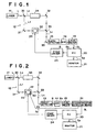
- a blood vessel distinguishing system in accordance with a first embodiment of the present invention comprises a laser 11 emitting a measuring light beam L at a wavelength of an optical heterodyne optical system 12, a photodetector 13 which receives the measuring light beam L emanating from the optical heterodyne optical system 12, a band-pass filter (BPF) 14 which is connected to the photodetector 13 and transmits only a signal in a predetermined frequency band to be described later, and a level meter 15 connected to the band-pass filter 14.
- BPF band-pass filter
- the system further comprises a personal computer (PC) 20 which receives output of the level meter 15 and forms an image signal generating means together with the level meter 15, and an image monitor 21 such as a CRT display connected to the personal computer 20.
- PC personal computer
- a X-Y stage 23 which is movable in X and Y directions supporting thereon an object (e.g., a human finger) 22.
- a stage driver 24 drives the X-Y stage 23 under the control of the personal computer 20.
- the optical system 12 and the photodetector 13 form an optical heterodyne detection system.
- the optical system 12 comprises a first half-silvered mirror 30 which splits the measuring light beam L into a first light beam L1 (the part of the measuring light beam L reflected by the first half-silvered mirror 30) and a second light beam L2 (the part of the measuring light beam L passing through the first half-silvered mirror 30), a first mirror 31 which reflects the first light beam L1 to impinge upon the object 22, a second mirror 32 which reflects the second light beam L2, a second half-silvered mirror 33 which combines the first light beam L1 passing through the object 22 with the second light beam L2 reflected from the second mirror 32 into a combined light beam Lc, and a third mirror 35 which reflects the combined light beam Lc to impinge upon the photodetector 13.
- a frequency shifter 34 provided on the optical path of the second light beam L2 shifts the second light beam L2 by a predetermined amount so that the center frequency of the second light beam L2 becomes ⁇ .
- the frequency shifter 34 may comprise, for instance, an AOM.
- a measuring light beam L is emitted from the laser 11 and the first light beam L1 is projected onto the object 22.
- the X-Y stage 23 is moved in X and Y directions, whereby the first light beam L1 is caused to two-dimensionally scan the object 22.
- the combined light beam Lc includes therein beat components whose center frequency is ⁇ , equal to that of the frequency-shifted second light beam L2.
- the output of the photodetector 13 upon receipt of the combined light beam Lc includes a beat signal B generated by the beat components.
- the output of the photodetector 13 is input into the band-pass filter 14.
- the beat signal B represents intensity of only straight light components traveling straight through the object 22, which is a scattering medium, or scattered light components close to the straight light components. Accordingly, by obtaining an image signal for the object 22 on the basis of the beat signal B, a high spatial resolution can be ensured though the measuring light beam L (the first light beam L1) is scattered by the object 22.
- the band-pass filter 14 selectively transmits signal components in a frequency band near the frequency ( ⁇ + ⁇ f) deviated from the center frequency ⁇ of the beat signal B by a predetermined width ⁇ f as shown by lines in Figure 5.
- the signal passing through the band-pass filter 14, that is, off-centered beat signal Bo is input into the level meter 15.
- the level meter 15 measures a level of the off-centered beat signal Bo at a predetermined timing, e.g., at a time at which the off-centered beat signal Bo takes a peak value, and inputs a level signal SL representing the measured level of the off-centered beat signal Bo into the personal computer 20.
- the personal computer 20 compares the level of the off-centered beat signal Bo represented by the level signal SL with a predetermined threshold level such as represented by d in Figure 5.
- a predetermined threshold level such as represented by d in Figure 5.
- the personal computer 20 When an artery is to be imaged, the personal computer 20 generates an image signal component Sp bearing thereon a relatively high density (low brightness) when the level of the off-centered beat signal Bo is higher than the threshold level and otherwise an image signal component Sp bearing thereon a relatively low density (high brightness), and inputs the image signal component Sp into the monitor 21.
- the level meter 15 outputs an off-centered beat signal Bo for each scanning spot on the object 22 as the first light beam L1 scans the object 22. Accordingly, the two-valued image signal component Sp is generated for each scanning spot on the object 22.
- the image monitor 21 reproduces a two-dimensional image on the basis of an image signal made up of the image signal components Sp thus generated for the respective scanning spots.
- the artery part is shown as a relatively high density part on a background at a relatively low density.
- the personal computer 20 when a vein is to be imaged, the personal computer 20 generates an image signal component Sp bearing thereon a relatively high density (low brightness) when the level of the off-centered beat signal Bo is lower than the threshold level and otherwise an image signal component Sp bearing thereon a relatively low density (high brightness), and inputs the image signal component Sp into the monitor 21.
- the image monitor 21 reproduces a two-dimensional image on the basis of an image signal made up of the image signal components Sp thus generated for the respective scanning spots.
- the vein part is shown as a relatively high density part on a background at a relatively low density.
- a blood vessel distinguishing system in accordance with a second embodiment of the present invention will be described with reference to Figure 2, hereinbelow.
- the blood vessel imaging system of this embodiment basically differs from that of the first embodiment in that there are provided a pulsation signal detecting means 50 which detects a pulsation wave of the object 22, and a synchronization detecting means 51 which samples the level signal SL on the basis of a pulsation signal Sc output from the pulsation signal detecting means 50.
- the synchronization detecting means 51 samples the level signal SL at times at which broadening of the spectrum of the beat signal B becomes of a predetermined phase (in this particular embodiment, times at which the flow rate of the arterial blood is maximized), and inputs the sampled level signal SL into the personal computer 20.
- the level of the off-centered beat signal Bo can be detected when broadening of the spectrum of the beat signal B is in a state shown by line a-1 in Figure 6 far from a state shown by line b representing broadening of the spectrum of the beat signal B when the measuring light beam L travels through a vein, whereby the artery part and the vein part can be imaged clearly distinguished from each other.
- a blood vessel distinguishing system in accordance with a third embodiment of the present invention will be described with reference to Figure 3, hereinbelow.
- the blood vessel imaging system of this embodiment basically differs from that of the second embodiment in that there are provided, in place of the pulsation signal detecting means 50, a second photodetector 63 which receives the combined light beam Lc, a second band-pass filter 64 which is connected to the photodetector 63 and transmits only a signal in a predetermined frequency band to be described later, and a second level meter 65 which is connected to the band-pass filter 64.
- the second band-pass filter 64 selectively transmits signal components in a frequency band near the center frequency ⁇ of the beat signal B included in the output of the second photodetector 63.
- the signal B ⁇ passing through the second band-pass filter 64 is input into the second level meter 65.
- the second level meter 65 outputs a timing signal St when the peak level of the signal B ⁇ falls below a preset value and inputs it into the synchronization detecting means 51.
- the synchronization detecting means 51 samples the level signal SL upon receipt of the timing signal St, and inputs the sampled level signal SL into the personal computer 20.
- the synchronization detecting means 51 can sample the level signal SL at times at which broadening of the spectrum of the beat signal B becomes of a predetermined phase (in this particular embodiment, times at which the flow rate of the arterial blood is maximized). Accordingly, the level of the off-centered beat signal Bo can be detected when broadening of the spectrum of the beat signal B is in a state shown by line a-1 in Figure 6 far from a state shown by line b representing broadening of the spectrum of the beat signal B when the measuring light beam L travels through a vein, whereby the artery part and the vein part can be imaged clearly distinguished from each other.
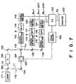
- a blood vessel imaging system in accordance with this embodiment comprises a laser 111 emitting a measuring light beam L at a wavelength of ⁇ , an optical heterodyne optical system 112, first to third photodetectors 113 to 115 which receive the measuring light beam L emanating from the optical heterodyne optical system 112, first to third band-pass filters (BPF) 116 to 118 which are respectively connected to the photodetectors 113 to 115 and selectively transmit signals in predetermined frequency bands to be described later, and first to third level meters 119 to 121 respectively connected to the band-pass filters 116 to 118.
- BPF band-pass filters
- the system further comprises a personal computer (PC) 222 which receives outputs of the level meters 119 to 121 and forms an image signal generating means together with the level meters 119 to 121, and an image monitor 123 such as a CRT display connected to the personal computer 122.
- PC personal computer
- a X-Y stage 125 which is movable in X and Y directions supporting thereon an object (e.g., a human finger) 124.
- a stage driver 126 drives the X-Y stage 125 under the control of the personal computer 122.
- the optical system 112 and the photodetectors 113 to 115 form an optical heterodyne detection system.
- the optical system 112 comprises a first half-silvered mirror 130 which splits the measuring light beam L into a first light beam L1 (the part of the measuring light beam L reflected by the first half-silvered mirror 130) and a second light beam L2 (the part of the measuring light beam L passing through the first half-silvered mirror 130), a first mirror 131 which reflects the first light beam L1 to impinge upon the object 124, a second mirror 132 which reflects the second light beam L2, and a second half-silvered mirror 133 which combines the first light beam L1 passing through the object 124 with the second light beam L2 reflected from the second mirror 132 into a combined light beam Lc and causes the combined light beam Lc to partly impinge upon the first photodetector 113 and partly impinge upon a third half-silvered mirror 135.
- the optical system 112 further comprises the third half-silvered mirror 135 and a third mirror 136 which reflects the part of the combined light beam Lc passing through the third half-silvered mirror 135 to impinge upon the third photodetector 115.
- the third half-silvered mirror 135 reflects a part of the combined light beam Lc to impinge upon the second photodetector 114 and transmits the other part of the combined light beam Lc.
- a frequency shifter 134 provided on the optical path of the second light beam L2 shifts the second light beam L2 by a predetermined amount so that the center frequency of the second light beam L2 becomes ⁇ .
- the frequency shifter 134 may comprise, for instance, an AOM.
- a measuring light beam L is emitted from the laser 111 and the first light beam L1 is projected onto the object 124. While projecting the first light beam L1, the X-Y stage 125 is moved in X and Y directions, whereby the first light beam L1 is caused to two-dimensionally scan the object 124.
- each of the combined light beams Lc includes therein beat components whose center frequency is ⁇ , equal to that of the frequency-shifted second light beam L2.
- the outputs of the photodetectors 113 to 115 upon receipt of the combined light beam Lc include a beat signal B generated by the beat components.
- the outputs of the photodetectors 113 to 115 are respectively input into the band-pass filters 116 to 118.
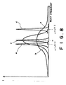
- the spectrum of the beat signal B becomes as shown by line a in Figure 8 when the first light beam L1 passes through an artery part and as shown by the line b in Figure 8 when the first light beam L1 passes through a vein part.
- the peak value of the intensity of the beat signal B becomes lower and the spectrum of the beat signal is broadened as the flow rate of the blood increases.
- the beat signal B represents intensity of only straight light components traveling straight through the object 124, which is a scattering medium, or scattered light components close to the straight light components. Accordingly, by obtaining an image signal for the object 124 on the basis of the beat signal B, a high spatial resolution can be ensured though the measuring light beam L (the first light beam L1) is scattered by the object 124.
- the band-pass filter 116 selectively transmits signal components in a frequency band near the center frequency ⁇ of the beat signal B as shown by line c in Figure 8.
- the band-pass filter 117 selectively transmits signal components in a frequency band near the frequency ( ⁇ + ⁇ f2) deviated from the center frequency ⁇ of the beat signal B toward the higher frequency side by a predetermined width ⁇ f2 as shown by line d in Figure 8.
- the band-pass filter 118 selectively transmits signal components in a frequency band near the frequency ( ⁇ - ⁇ f3) deviated from the center frequency ⁇ of the beat signal B toward the lower frequency side by a predetermined width ⁇ f3 as shown by line e in Figure 8.
- the widths ⁇ f2 and ⁇ f3 are set so that the former is larger than the latter, that is, Af2>Af3.
- the outputs of the band-pass filters 116 to 118 are respectively input into the level meters 119 to 121.
- the level meters 119 to 121 measure levels of the input signals at a predetermined timing, e.g., at a time at which the signal levels are maximized, and input signals representing the measured levels of the signals B( ⁇ ), B( ⁇ + ⁇ f2) and B( ⁇ - ⁇ f3) into the personal computer 122.
- the personal computer 20 calculates an intensity ratio I(w+Of2)/I(w) when an artery is to be imaged, and generates an image signal component Sp which bears thereon a higher density (lower brightness) as the intensity ratio increase, and inputs the image signal component Sp into the monitor 123.
- the image monitor 123 reproduces a two-dimensional image on the basis of an image signal made up of the image signal components Sp thus generated for the respective scanning spots.
- the artery part is shown as a relatively high density part.
- the personal computer 20 calculates an intensity ratio I( ⁇ - ⁇ f3)/I( ⁇ ), and generates an image signal component Sp which bears thereon a higher density (lower brightness) as the intensity ratio decreases, and inputs the image signal component Sp into the monitor 123.
- the image monitor 123 reproduces a two-dimensional image on the basis of an image signal made up of the image signal components Sp thus generated for the respective scanning spots.
- the vein part is shown as a relatively high density part.
- the image signal component Sp is generated so that the image signal components bears thereon a higher density as the intensity ratio I( ⁇ + ⁇ f2)/I( ⁇ ) increases when an artery image is to be displayed, and the image signal components bears thereon a higher density as the intensity ratio I( ⁇ + ⁇ f2)/I( ⁇ ) decreases when a vein image is to be displayed.
- the image signal component Sp is generated in the manner described above, it becomes unnecessary to generate an image signal component Sp representing a vein image on the basis of an extremely small value (close to 0) of the intensity ratio I(w+ ⁇ f2)/I( ⁇ ) or to generate an image signal component Sp representing an artery image on the basis of an extremely large value (close to 1) of the intensity ratio I( ⁇ - ⁇ f3)/I( ⁇ ), whereby handling of the signals is facilitated.
- FIG. 9 A blood vessel distinguishing system in accordance with a fifth embodiment of the present invention will be described with reference to Figure 9, hereinbelow.
- Figure 9 the elements analogous to those shown in Figure 7 are given the same reference numerals and will not be described here.
- the frequency-shifted second light beam L2 and the first light beam L1 passing through the object 124 are combined into a single combined light beam Lc by the second half-silvered mirror 133, and the single combined light beam Lc is reflected by a mirror 136 to impinge upon a single photodetector 115.
- the beat signal B output from the photo 115 is input into a frequency analyzer 150 and the output of the frequency analyzer 150 is input into the personal computer 122.
- the frequency analyzer 150 obtains the spectrum of the beat signal B, and obtains a half width W (full width at half maximum) of the spectrum. As shown in Figure 10, the half width W is a spectral width between two frequencies at which the intensity of the beat signal B becomes a half of the intensity of the beat signal B at the center frequency ⁇ , at which the intensity of the beat signal B is maximized. Then the frequency analyzer 150 inputs a signal SW representing the half width W into the personal computer 122.
- the personal computer 122 generates an image signal component Sp which bears thereon a higher density (lower brightness) as the half width W increases, and inputs the image signal component Sp into the monitor 123.
- the image monitor 123 reproduces a two-dimensional image on the basis of an image signal made up of the image signal components Sp thus generated for the respective scanning spots.
- the artery part is shown as a relatively high density part while the vein part is shown as a relatively low density part.
- the flow rate measuring system comprises a laser 201 which projects measuring light L onto light scattering fluid 200 flowing at a flow rate V, a frequency analysis means 202, and a signal analysis means 203 which forms a flow rate analysis means together with the frequency analysis means 202.
- the frequency analysis means 202 a condenser leans 210 which condenses the measuring light L scattered by the scattering fluid 200, a collimator lens 211 which parallels the scattered measuring light L condensed by the condenser lens 210, a condenser lens 212 which condenses the measuring light L paralleled by the collimator lens 211, a photodetector 213 which detects the measuring light L condensed by the condenser lens 212, and a pair of half-silvered mirrors 220 and 221 which are disposed between the collimator lens 211 and the condenser lens 212 and form a Fabry-Perot interferometer.
- the half-silvered mirror 220 is fixed whereas the half-silvered mirror 221 is moved back and forth in the direction of arrow H by a drive means not shown.
- the signal analysis means 203 comprises a computer system and a light detection signal SQ is input into the signal analysis means 203 from the photodetector 213.
- the measuring light L is projected onto the fluid 200.
- the measuring light L scattered by the fluid 200 is caused to impinge upon the photodetector 213 by the condenser lens 210, the collimator lens 211 and the condenser lens 212 and the amount of measuring light L is detected by the photodetector 213.
- light components at wavelengths (frequencies) which generate standing wave between the half-silvered mirrors 221 and 220 enhance each other by light interference, and the light components of the measuring light L at the frequencies are detected by the photodetector 213.
- the half-silvered mirror 221 is moved in one direction and the distance of the half-silvered mirror 221 from the half-silvered mirror 220 continuously changes, the frequency of the light components detected by the photodetector 213 continuously changes.
- the light detection signal QS output from the photodetector 213 as the half-silvered mirror 221 is moved in one direction represents the intensity E of the detected light component at each frequency.
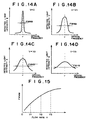
- the relation between the frequency and the intensity E of the detected light component varies with the flow rate of the fluid 200 as shown in Figures 14A to 14D.
- Figures 14A to 14D respectively show the relations when the flow rate V of the fluid 200 is 0, V1, V2 and V3 (V1 ⁇ V2 ⁇ V3).
- v represents the center frequency.
- the signal analysis means 203 receives the light detection signal QS and obtains the half width FWHM of the spectrum. Then the signal analysis means 203 determines the flow rate V on the basis of the relation between the half width FWHM and the flow rate V which has been empirically determined. The flow rate V thus determined is shown by a display means such as a liquid crystal panel.
- the flow rate V is determined on the basis of the spectrum half width FWHM of the detected light
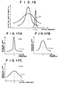
- the flow rate V may be determined on the basis of broadening of detected light spectrum by other methods. For instance, when the light detection signal QS output from the photodetector 213 is passed through a band-pass filter whose transmission characteristic is such that the center frequency is deviated from the center frequency ⁇ of the detected light by ⁇ (off-centered frequency components) as shown by curve c1 in Figure 16, the intensity of the frequency components transmitted through the band-pass filter is higher as the broadening of the spectrum increases, i.e., the flow rate V increases. Accordingly, the flow rate V can be obtained according to the intensity of the off-centered frequency components.
- the intensity ratio E( ⁇ +A ⁇ )/E( ⁇ ) is obtained as shown in Figures 17A to 17C
- the intensity ratio is higher as the broadening of the spectrum increases, i.e., the flow rate V increases as shown in Figure 18. Accordingly, the flow rate V can be obtained according to the intensity ratio.
- the flow rate V can be determined according to the half width W.
- the intensity ratio I( ⁇ + ⁇ f)/I( ⁇ )) is obtained, the intensity ratio is higher as the Doppler broadening of the spectrum of the beat signal B increases, i.e., the flow rate V increases. Accordingly, the flow rate V can be obtained according to the intensity ratio.
- the level signal SL output from the synchronization detecting means 51 in the blood vessel imaging system shown in Figure 3 represents a higher level when the measuring light beam L passes though scattering fluid flowing at a higher flow rate as described above with reference to Figure 5. Accordingly, the flow rate V can also be obtained according to the level signal SL.
Landscapes
- Health & Medical Sciences (AREA)
- Life Sciences & Earth Sciences (AREA)
- Heart & Thoracic Surgery (AREA)
- Medical Informatics (AREA)
- Physics & Mathematics (AREA)
- Cardiology (AREA)
- Biophysics (AREA)
- Pathology (AREA)
- Engineering & Computer Science (AREA)
- Biomedical Technology (AREA)
- Hematology (AREA)
- Physiology (AREA)
- Molecular Biology (AREA)
- Surgery (AREA)
- Animal Behavior & Ethology (AREA)
- General Health & Medical Sciences (AREA)
- Public Health (AREA)
- Veterinary Medicine (AREA)
- Measuring Pulse, Heart Rate, Blood Pressure Or Blood Flow (AREA)
- Investigating Or Analysing Materials By Optical Means (AREA)
Claims (16)
- Blutgefäß-Unterscheidungssystem, umfassend
eine Meßlichtprojektionseinrichtung (11, 12; 111, 112; 201), die Meßlicht auf einen Organismus (22; 124) projiziert, und
eine Unterscheidungseinrichtung (13-15; 20, 21; 63-65; 113-123; 115, 150, 122; 203), welches arteriellen von venösem Blutstrom in dem Organismus unterscheidet anhand einer Verbreiterung eines Spektrums aufgrund einer Wechselwirkung des Meßlichts mit dem Organismus (22; 124). - System nach Anspruch 1, bei dem die Unterscheidungseinrichtung (150, 203) Frequenzkomponenten des Meßlichts detektiert, die von dem Organismus gestreut wurden, die halbe Breite des Spektrums des Frequenz-Detektiersignals erfaßt und arteriellen von venösem Blutstrom in dem Organismus auf der Grundlage der Halbwertsbreite unterscheidet.
- System nach Anspruch 1, bei dem die Unterscheidungseinrichtung (13-15; 20, 21; 63-65; 113-123) eine Einrichtung ist, die Frequenzkomponenten des Meßlichts, die von dem Organismus (22, 124) gestreut wurden, detektiert, die Intensität der außermittigen Komponenten in einem Frequenzband detektiert, die von der Mittenfrequenz des Frequenzdetektiersignals um eine vorbestimmte Breite abweichen, und arteriellen von venösem Blutstrom auf der Grundlage der Intensität unterscheidet.
- System nach Anspruch 1, indem die Unterscheidungseinrichtung (113-123) eine Einrichtung ist, die von dem Organismus gestreute Frequenzkomponenten des Meßlichts detektiert, das Verhältnis zwischen der Intensität von Mittenfrequenzkomponenten des Frequenzdetektiersignals und der Intensität der außermittigen Komponenten in einem Frequenzband, welches von der Mittenfrequenz des Frequenzdetektiersignals um eine vorbestimmte Breite abweicht, detektiert und arteriellen von venösem Blutstrom in dem Organismus auf der Grundlage des Intensitätsverhältnisses unterscheidet.
- System nach Anspruch 1, bei dem die Unterscheidungseinrichtung (13-15; 20, 21; 63-65; 113-123) eine Einrichtung ist, die von dem Organismus gestreute Frequenzkomponenten des Meßlichts anhand eines optischen Überlagerungs-Detektiersignals erfaßt.
- System nach Anspruch 1, umfassend:eine Abtasteinrichtung (23, 24; 125, 126), die veranlaßt, daß das Meßlicht einen Organismus (22; 124) abtastet,ein optisches Überlagerungs-Detektiersystem (12; 112), bestehend aus einem optischen System (30-33; 130-133), die das Meßlicht stromaufwärts bezüglich des Organismus (22; 124) auftrennt in einen ersten Lichtstrahl, der weiterläuft, um auf den Organismus (22; 124) aufzutreffen, und einen zweiten Lichtstrahl, der nicht auf den Organismus auftrifft, und den zweiten Lichtstrahl mit dem ersten Lichtstrahl, der von dem Organismus kommt, zu einem kombinierten Lichtstrahl kombiniert, aus einem Frequenzschieber (34; 134), der bewirkt, daß der erste Lichtstrahl und der zweite Lichtstrahl voneinander verschiedene Frequenzen besitzen, und eine Schwebungskomponenten-Detektiereinrichtung (13-15; 63-65; 113-121; 202), die Schwebungskomponenten des kombinierten Lichtstrahls detektiert, wobei die Unterscheidungseinrichtung aufweist:eine Filtereinrichtung (14; 64; 116-118), die aus dem von der Schwebungskomponenten-Detektiereinrichtung ausgegebenen Schwebungskomponenten-Detektiersignal außermittige Komponenten in einem gegenüber der Mittenfrequenz des Schwebungskomponenten-Detektiersignal um eine vorbestimmte Breite abweichenden Frequenzband detektiert, undeine Bildsignalerzeugungseinrichtung (20, 21; 122, 123), die ein Bildsignal erzeugt, welches wiederspiegelt, ob das von der Filtereinrichtung detektierte außermittige Schwebungssignal oberhalb oder unterhalb eines vorbestimmten Schwellenwerts liegt.
- System nach Anspruch 6, bei dem die Bildsignalerzeugungseinrichtung (20, 21; 122, 123) ein Bildsignal erzeugt, welches einen arteriellen Blutstrom in dem Organismus repräsentiert, basierend auf Komponenten des außermittigen Schwebungssignals, die oberhalb des vorbestimmten Schwellenwerts liegen.
- System nach Anspruch 6, bei dem die Bildsignalerzeugungseinrichtung (20, 21; 122, 123) ein Bildsignal erzeugt, welches einen venösen Blutstrom in dem Organismus auf der Grundlage von Komponenten des außermittigen Schwebungssignals repräsentiert, die niedriger sind als der vorbestimmte Schwellenwert.
- System nach Anspruch 6, bei dem die Unterscheidungseinrichtung außerdem eine gleichphasige Zeitdetektoreinrichtung (15, 65) enthält, die phasengleiche Zeitpunkte detektiert, zu denen eine Verbreiterung des Spektrums des Schwebungskomponenten-Detektiersignals eine vorbestimmte Phase annimmt, außerdem eine Synchronisationsdetektoreinrichtung (51) aufweist, welche das außermittige Schwebungssignal zu den phasengleichen Zeitpunkten abtastet und das so erhaltene außermittige Schwebungssignal in die Bildsignalerzeugungseinrichtung eingibt.
- System nach Anspruch 9, bei dem die phasengleiche Zeitdetektoreinrichtung (15, 65) eine Einrichtung zum Detektieren der lmpulswelle des Organismus (22, 124) ist.
- System nach Anspruch 9, bei dem die phasengleiche Zeitdetektoreinrichtung eine Einrichtung ist zum Detektieren der Zeitpunkte, zu denen die Mittenfrequenzkomponente des Schwebungskomponenten-Detektiersignals einen vorbestimmten Spitzenwert annimmt.
- System nach Anspruch 6, bei dem die Meßlicht-Projektionseinrichtung (11; 111; 201) ein linienförmiges zweidimensionales Array aus mehreren Lichtemissionsabschnitten enthält,
wobei das optische Überlagerungs-Detektiersystem (12; 112) dazu ausgebildet ist, parallel Schwebungskomponenten der kombinierten Lichtstrahlen basierend auf den Meßlichtstrahlen von den einzelnen Lichtemissionsabschnitten zu detektieren, und
die Meßlicht-Projektionseinrichtung (11; 111; 201) und das optische Überlagerungs-Detektiersystem (12; 112) außerdem zumindest als Teil der Abtasteinrichtung (23, 24; 125, 126) fungieren. - System nach Anspruch 6, bei dem die Unterscheidungseinrichtung aufweist:eine erste Intensitätsdetektiereinrichtung (13), die die Intensität der Mittenfrequenzkomponenten des Schwebungskomponenten-Detektiersignals erfaßt, die von der Schwebungskomponenten-Detektiereinrichtung ausgegeben werden, undein zweite Intensitätsdetektiereinrichtung (63), die die Intensität der außermittigen Komponenten des Schwebungskomponenten-Detektiersignals in einem von der Mittenfrequenz des Schwebungskomponenten-Detektiersignals um eine vorbestimmte Breite abweichenden Frequenzbands detektiert, wobeidie Bildsignal-Erzeugungseinrichtung (21, 22; 122, 123) ein Bildsignal auf der Grundlage des Verhältnisses der Intensität der außermittigen Komponenten des Schwebungskomponenten-Detektiersignals zu der Intensität der Mittenfrequenzkomponenten des Schwebungskomponenten-Detektiersignals erzeugt.
- System nach Anspruch 13, bei dem die zweite Intensitäts-Detektiereinrichtung (63) die Intensitäten der ersten und der zweiten mittigen Komponenten des Schwebungskomponenten-Detektiersignals in verschiedenen Frequenzbändern erfaßt, und
die Bildsignalerzeugungseinrichtung ein Bildsignal für den arteriellen Blutstrom in dem Organismus auf der Grundlage des Verhältnisses der Intensität der Mittenfrequenzkomponenten zu derjenigen der ersten außermittigen Komponenten erzeugt, und ein Bildsignal über venöse Teile des Organismus auf der Grundlage des Verhältnisses der Intensität der Mittenfrequenzkomponenten zu jener der zweiten außermittigen Komponenten erzeugt. - System nach Anspruch 6, bei dem die Unterscheidungseinrichtung aufweist:eine Spektralanalyseeinrichtung (150, 203), die das Spektrum des Schwebungskomponenten-Detektiersignals ermittelt, welches von der Schwebungskomponenten-Detektiereinrichtung (202) ausgegeben wird, undeine Bildsignalerzeugungseinrichtung, die ein Bildsignal auf der Grundlage einer spektralen Breite zwischen zwei Frequenzen erzeugt, bei denen die Intensität des Schwebungskomponenten-Detektiersignals einen vorbestimmten Wert in Bezug auf die Intensität der Mittenfrequenzkomponenten annimmt.
- System nach Anspruch 15, bei dem die Bildsignalerzeugungseinrichtung als spektrale Breite die halbe Breite des Spektrums verwendet, welches von der Spektralanalyseeinrichtung (150, 203) erhalten wird.
Applications Claiming Priority (4)
| Application Number | Priority Date | Filing Date | Title |
|---|---|---|---|
| JP33076598 | 1998-11-20 | ||
| JP33076498 | 1998-11-20 | ||
| JP33076598 | 1998-11-20 | ||
| JP33076498 | 1998-11-20 |
Publications (3)
| Publication Number | Publication Date |
|---|---|
| EP1002497A2 EP1002497A2 (de) | 2000-05-24 |
| EP1002497A3 EP1002497A3 (de) | 2001-05-16 |
| EP1002497B1 true EP1002497B1 (de) | 2006-07-26 |
Family
ID=26573631
Family Applications (1)
| Application Number | Title | Priority Date | Filing Date |
|---|---|---|---|
| EP99123025A Expired - Lifetime EP1002497B1 (de) | 1998-11-20 | 1999-11-19 | Blutgefäss Bilddarstellungssystem |
Country Status (3)
| Country | Link |
|---|---|
| US (1) | US6374128B1 (de) |
| EP (1) | EP1002497B1 (de) |
| DE (1) | DE69932485T2 (de) |
Families Citing this family (103)
| Publication number | Priority date | Publication date | Assignee | Title |
|---|---|---|---|---|
| US6556854B1 (en) | 1998-11-20 | 2003-04-29 | Fuji Photo Film Co., Ltd. | Blood vessel imaging system using homodyne and heterodyne effects |
| US6542246B1 (en) * | 1998-11-20 | 2003-04-01 | Fuji Photo Film Co., Ltd. | Blood vessel imaging system |
| JP2000155090A (ja) * | 1998-11-20 | 2000-06-06 | Fuji Photo Film Co Ltd | 血管の画像化装置 |
| US8078263B2 (en) * | 2000-01-19 | 2011-12-13 | Christie Medical Holdings, Inc. | Projection of subsurface structure onto an object's surface |
| US7239909B2 (en) * | 2000-01-19 | 2007-07-03 | Luminetx Technologies Corp. | Imaging system using diffuse infrared light |
| DE60141090D1 (de) | 2000-10-30 | 2010-03-04 | Gen Hospital Corp | Optische systeme zur gewebeanalyse |
| US9295391B1 (en) | 2000-11-10 | 2016-03-29 | The General Hospital Corporation | Spectrally encoded miniature endoscopic imaging probe |
| WO2002088705A2 (en) * | 2001-05-01 | 2002-11-07 | The General Hospital Corporation | Method and apparatus for determination of atherosclerotic plaque type by measurement of tissue optical properties |
| US6939310B2 (en) * | 2001-10-10 | 2005-09-06 | Lifescan, Inc. | Devices for physiological fluid sampling and methods of using the same |
| US7024027B1 (en) * | 2001-11-13 | 2006-04-04 | Koninklijke Philips Electronics N.V. | Method and apparatus for three-dimensional filtering of angiographic volume data |
| US7355716B2 (en) * | 2002-01-24 | 2008-04-08 | The General Hospital Corporation | Apparatus and method for ranging and noise reduction of low coherence interferometry LCI and optical coherence tomography OCT signals by parallel detection of spectral bands |
| US20110201924A1 (en) * | 2002-04-30 | 2011-08-18 | The General Hospital Corporation | Method and Apparatus for Improving Image Clarity and Sensitivity in Optical Tomography Using Dynamic Feedback to Control Focal Properties and Coherence Gating |
| US8054468B2 (en) * | 2003-01-24 | 2011-11-08 | The General Hospital Corporation | Apparatus and method for ranging and noise reduction of low coherence interferometry LCI and optical coherence tomography OCT signals by parallel detection of spectral bands |
| CA2519937C (en) | 2003-03-31 | 2012-11-20 | Guillermo J. Tearney | Speckle reduction in optical coherence tomography by path length encoded angular compounding |
| EP2280260B1 (de) * | 2003-06-06 | 2017-03-08 | The General Hospital Corporation | Verfahren und Vorrichtung für eine Lichtquelle mit Abstimmung der Wellenlänge |
| JP5567246B2 (ja) | 2003-10-27 | 2014-08-06 | ザ ジェネラル ホスピタル コーポレイション | 周波数ドメイン干渉測定を利用して光学撮像を実行する方法および装置 |
| US8160667B2 (en) * | 2003-11-26 | 2012-04-17 | Hitachi Medical Corporation | Biological light measuring apparatus and method |
| WO2005117534A2 (en) | 2004-05-29 | 2005-12-15 | The General Hospital Corporation | Process, system and software arrangement for a chromatic dispersion compensation using reflective layers in optical coherence tomography (oct) imaging |
| AU2005270037B2 (en) | 2004-07-02 | 2012-02-09 | The General Hospital Corporation | Endoscopic imaging probe comprising dual clad fibre |
| EP1782020B1 (de) * | 2004-08-06 | 2012-10-03 | The General Hospital Corporation | Prozess, system und softwareanordnung zur bestimmung mindestens einer position in einer probe unter verwendung von optischer kohärenztomographie |
| WO2006024014A2 (en) | 2004-08-24 | 2006-03-02 | The General Hospital Corporation | Process, system and software arrangement for measuring a mechanical strain and elastic properties of a sample |
| WO2006024015A1 (en) | 2004-08-24 | 2006-03-02 | The General Hospital Corporation | Method and apparatus for imaging of vessel segments |
| JP5215664B2 (ja) | 2004-09-10 | 2013-06-19 | ザ ジェネラル ホスピタル コーポレイション | 光学コヒーレンス撮像のシステムおよび方法 |
| JP4997112B2 (ja) | 2004-09-29 | 2012-08-08 | ザ ジェネラル ホスピタル コーポレイション | 少なくとも1つの電磁放射を伝送させるための装置およびその製造方法 |
| EP2278265A3 (de) | 2004-11-24 | 2011-06-29 | The General Hospital Corporation | Interferometer mit gemeinsamem Pfad für endoskopische optische Kohärenztomographie |
| US8922781B2 (en) | 2004-11-29 | 2014-12-30 | The General Hospital Corporation | Arrangements, devices, endoscopes, catheters and methods for performing optical imaging by simultaneously illuminating and detecting multiple points on a sample |
| US7225005B2 (en) * | 2004-12-14 | 2007-05-29 | Intelligent Medical Devices, Inc. | Optical determination of in vivo properties |
| US20070004976A1 (en) * | 2004-12-14 | 2007-01-04 | Zelenchuk Alex R | In vivo optical measurements of hematocrit |
| US20060129038A1 (en) * | 2004-12-14 | 2006-06-15 | Zelenchuk Alex R | Optical determination of in vivo properties |
| EP2085929A1 (de) | 2005-04-28 | 2009-08-05 | The General Hospital Corporation | Beurteilung von optischen Kohärenztomographieinformationen für eine anatomische Struktur |
| EP1888152A2 (de) * | 2005-05-10 | 2008-02-20 | Koninklijke Philips Electronics N.V. | Kanüleneinführungssystem |
| SE0501078L (sv) * | 2005-05-12 | 2006-11-13 | Spectracure Ab | En anordning för att analysera ett vätskeflöde |
| EP1889037A2 (de) | 2005-06-01 | 2008-02-20 | The General Hospital Corporation | Vorrichtung, verfahren und system zur abbildung phasenaufgelöster optischer frequenzdomänen |
| ATE484727T1 (de) | 2005-08-09 | 2010-10-15 | Gen Hospital Corp | Gerät und verfahren zur durchführung von polarisationsbasierter quadraturdemodulation bei optischer kohärenztomographie |
| AU2006299659A1 (en) | 2005-09-29 | 2007-04-12 | General Hospital Corporation | Method and apparatus for method for viewing and analyzing of one or more biological samples with progressively increasing resolutions |
| US7889348B2 (en) | 2005-10-14 | 2011-02-15 | The General Hospital Corporation | Arrangements and methods for facilitating photoluminescence imaging |
| EP1971848B1 (de) * | 2006-01-10 | 2019-12-04 | The General Hospital Corporation | Systeme und verfahren zur datengenerierung auf der basis eines oder mehrerer spektral kodierter endoskopieverfahren |
| ES2847854T3 (es) | 2006-01-19 | 2021-08-04 | Massachusetts Gen Hospital | Catéter de globo de obtención de imágenes |
| US8145018B2 (en) | 2006-01-19 | 2012-03-27 | The General Hospital Corporation | Apparatus for obtaining information for a structure using spectrally-encoded endoscopy techniques and methods for producing one or more optical arrangements |
| US7538859B2 (en) | 2006-02-01 | 2009-05-26 | The General Hospital Corporation | Methods and systems for monitoring and obtaining information of at least one portion of a sample using conformal laser therapy procedures, and providing electromagnetic radiation thereto |
| EP1983921B1 (de) * | 2006-02-01 | 2016-05-25 | The General Hospital Corporation | Systeme zur bereitstellung elektromagnetischer strahlung für mindestens einen teil einer probe mittels konformer lasertherapieverfahren |
| EP3143926B1 (de) * | 2006-02-08 | 2020-07-01 | The General Hospital Corporation | Verfahren, anordnungen und systeme zum abrufen von informationen im zusammenhang mit einer anatomischen probe mithilfe eines optischen mikroskops |
| US7982879B2 (en) | 2006-02-24 | 2011-07-19 | The General Hospital Corporation | Methods and systems for performing angle-resolved fourier-domain optical coherence tomography |
| US7742173B2 (en) | 2006-04-05 | 2010-06-22 | The General Hospital Corporation | Methods, arrangements and systems for polarization-sensitive optical frequency domain imaging of a sample |
| EP3150110B1 (de) | 2006-05-10 | 2020-09-02 | The General Hospital Corporation | Verfahren, anordnungen und systeme zur bereitstellung von frequenzbereichsabbildung einer probe |
| US7782464B2 (en) | 2006-05-12 | 2010-08-24 | The General Hospital Corporation | Processes, arrangements and systems for providing a fiber layer thickness map based on optical coherence tomography images |
| EP2054712B1 (de) | 2006-08-25 | 2015-10-07 | The General Hospital Corporation | Vorrichtungen und verfahren zur verstärkung einer optischen kohärenztomographie-abbildung mithilfe volumetrischer filterungsverfahren |
| US8838213B2 (en) | 2006-10-19 | 2014-09-16 | The General Hospital Corporation | Apparatus and method for obtaining and providing imaging information associated with at least one portion of a sample, and effecting such portion(s) |
| EP2104968A1 (de) | 2007-01-19 | 2009-09-30 | The General Hospital Corporation | Drehscheiben-reflexion zur schnellen erfassung der wellenlänge von dispergiertem licht |
| WO2008089406A2 (en) * | 2007-01-19 | 2008-07-24 | The General Hospital Corporation | Apparatus and method for simultaneous inspection at different depths based on the principle of frequency domain optical coherence tomography |
| EP2602651A3 (de) | 2007-03-23 | 2014-08-27 | The General Hospital Corporation | Verfahren, Anordnungen und Vorrichtung zur Verwendung eines wellenlängengewobbelten Lasers anhand von Winkelabtastungs- und Dispersionsverfahren |
| WO2008121844A1 (en) | 2007-03-30 | 2008-10-09 | The General Hospital Corporation | System and method providing intracoronary laser speckle imaging for the detection of vulnerable plaque |
| US8045177B2 (en) * | 2007-04-17 | 2011-10-25 | The General Hospital Corporation | Apparatus and methods for measuring vibrations using spectrally-encoded endoscopy |
| EP2173254A2 (de) | 2007-07-31 | 2010-04-14 | The General Hospital Corporation | System und verfahren zur bereitstellung von strahlerfassungsmustern für hochgeschwindigkeits-abbildungen optischer dopplerfrequenzdomänen |
| US8040608B2 (en) | 2007-08-31 | 2011-10-18 | The General Hospital Corporation | System and method for self-interference fluorescence microscopy, and computer-accessible medium associated therewith |
| WO2009059034A1 (en) | 2007-10-30 | 2009-05-07 | The General Hospital Corporation | System and method for cladding mode detection |
| US7898656B2 (en) * | 2008-04-30 | 2011-03-01 | The General Hospital Corporation | Apparatus and method for cross axis parallel spectroscopy |
| EP2274572A4 (de) | 2008-05-07 | 2013-08-28 | Gen Hospital Corp | System, verfahren und computermedium zur verfolgung einer gefässbewegung in einer dreidimensionalen koronararterienmikroskopie |
| EP2288948A4 (de) | 2008-06-20 | 2011-12-28 | Gen Hospital Corp | Anordnung aus kondensierten glasfaserkopplern und verfahren zu ihrer verwendung |
| WO2010009136A2 (en) | 2008-07-14 | 2010-01-21 | The General Hospital Corporation | Apparatus and methods for color endoscopy |
| US9414805B2 (en) * | 2008-07-28 | 2016-08-16 | Siemens Medical Solutions Usa, Inc. | Spectral Doppler with multiple spatially distinct gates |
| ES2957932T3 (es) * | 2008-12-10 | 2024-01-30 | Massachusetts Gen Hospital | Sistemas, aparatos y procedimientos para ampliar el rango de profundidad de imagen de tomografía de coherencia óptica mediante submuestreo óptico |
| JP2012515576A (ja) * | 2009-01-20 | 2012-07-12 | ザ ジェネラル ホスピタル コーポレイション | 内視鏡生検装置、システム、及び方法 |
| JP2012515930A (ja) | 2009-01-26 | 2012-07-12 | ザ ジェネラル ホスピタル コーポレーション | 広視野の超解像顕微鏡を提供するためのシステム、方法及びコンピューターがアクセス可能な媒体 |
| US8254023B2 (en) * | 2009-02-23 | 2012-08-28 | Visiongate, Inc. | Optical tomography system with high-speed scanner |
| WO2010105197A2 (en) | 2009-03-12 | 2010-09-16 | The General Hospital Corporation | Non-contact optical system, computer-accessible medium and method for measuring at least one mechanical property of tissue using coherent speckle techniques(s) |
| US11490826B2 (en) * | 2009-07-14 | 2022-11-08 | The General Hospital Corporation | Apparatus, systems and methods for measuring flow and pressure within a vessel |
| HRP20201813T1 (hr) | 2010-03-05 | 2021-03-19 | The General Hospital Corporation | Uređaj za pružanje elektromagnetnog zračenja na uzorak |
| US9069130B2 (en) | 2010-05-03 | 2015-06-30 | The General Hospital Corporation | Apparatus, method and system for generating optical radiation from biological gain media |
| EP2575597B1 (de) | 2010-05-25 | 2022-05-04 | The General Hospital Corporation | Vorrichtung zur bereitstellung einer optischen bildgebung für strukturen und zusammensetzungen |
| WO2011150069A2 (en) | 2010-05-25 | 2011-12-01 | The General Hospital Corporation | Apparatus, systems, methods and computer-accessible medium for spectral analysis of optical coherence tomography images |
| WO2011153434A2 (en) | 2010-06-03 | 2011-12-08 | The General Hospital Corporation | Apparatus and method for devices for imaging structures in or at one or more luminal organs |
| EP2632324A4 (de) | 2010-10-27 | 2015-04-22 | Gen Hospital Corp | Vorrichtungen, systeme und verfahren zur blutdruckmessung in mindestens einem gefäss |
| JP2014523536A (ja) | 2011-07-19 | 2014-09-11 | ザ ジェネラル ホスピタル コーポレイション | 光コヒーレンストモグラフィーにおいて偏波モード分散補償を提供するためのシステム、方法、装置およびコンピュータアクセス可能な媒体 |
| WO2013029047A1 (en) | 2011-08-25 | 2013-02-28 | The General Hospital Corporation | Methods, systems, arrangements and computer-accessible medium for providing micro-optical coherence tomography procedures |
| US9341783B2 (en) | 2011-10-18 | 2016-05-17 | The General Hospital Corporation | Apparatus and methods for producing and/or providing recirculating optical delay(s) |
| US11399898B2 (en) | 2012-03-06 | 2022-08-02 | Briteseed, Llc | User interface for a system used to determine tissue or artifact characteristics |
| US9629528B2 (en) | 2012-03-30 | 2017-04-25 | The General Hospital Corporation | Imaging system, method and distal attachment for multidirectional field of view endoscopy |
| EP2852315A4 (de) | 2012-05-21 | 2016-06-08 | Gen Hospital Corp | Einrichtung, vorrichtung und verfahren für kapselmikroskopie |
| EP2948758B1 (de) | 2013-01-28 | 2024-03-13 | The General Hospital Corporation | Vorrichtung zur bereitstellung von gemeinsam mit optischer frequenzdomänenbildgebung aufgezeichneter diffuser spektroskopie |
| US10893806B2 (en) | 2013-01-29 | 2021-01-19 | The General Hospital Corporation | Apparatus, systems and methods for providing information regarding the aortic valve |
| WO2014121082A1 (en) | 2013-02-01 | 2014-08-07 | The General Hospital Corporation | Objective lens arrangement for confocal endomicroscopy |
| WO2014144709A2 (en) | 2013-03-15 | 2014-09-18 | The General Hospital Corporation | Methods and systems for characterizing an object |
| US9784681B2 (en) | 2013-05-13 | 2017-10-10 | The General Hospital Corporation | System and method for efficient detection of the phase and amplitude of a periodic modulation associated with self-interfering fluorescence |
| EP3692887B1 (de) | 2013-07-19 | 2024-03-06 | The General Hospital Corporation | Bildgebungsvorrichtung mithilfe von endoskopie mit multidirektionalem sichtfeld |
| EP3021735A4 (de) | 2013-07-19 | 2017-04-19 | The General Hospital Corporation | Bestimmung der augenbewegung mittels netzhautabbildung mit rückkopplung |
| EP3910282B1 (de) | 2013-07-26 | 2024-01-17 | The General Hospital Corporation | Verfahren zur erzeugung von laserstrahlung mit einer optische dispersion nutzenden laseranordnung für anwendungen in der fourier-raum optischen kohärenztomographie |
| US9733460B2 (en) | 2014-01-08 | 2017-08-15 | The General Hospital Corporation | Method and apparatus for microscopic imaging |
| US10736494B2 (en) | 2014-01-31 | 2020-08-11 | The General Hospital Corporation | System and method for facilitating manual and/or automatic volumetric imaging with real-time tension or force feedback using a tethered imaging device |
| JP6511471B2 (ja) | 2014-03-25 | 2019-05-15 | ブライトシード・エルエルシーBriteseed,Llc | 脈管検出器及び検出方法 |
| US10228556B2 (en) | 2014-04-04 | 2019-03-12 | The General Hospital Corporation | Apparatus and method for controlling propagation and/or transmission of electromagnetic radiation in flexible waveguide(s) |
| US10912462B2 (en) | 2014-07-25 | 2021-02-09 | The General Hospital Corporation | Apparatus, devices and methods for in vivo imaging and diagnosis |
| SG11201706298PA (en) * | 2015-02-03 | 2017-09-28 | Univ Vanderbilt | Intravenous access device detecting intravenous infiltration and in-vein placement |
| US10820838B2 (en) | 2015-02-19 | 2020-11-03 | Briteseed, Llc | System for determining vessel size using light absorption |
| US11490820B2 (en) | 2015-02-19 | 2022-11-08 | Briteseed, Llc | System and method for determining vessel size and/or edge |
| JP7057277B2 (ja) | 2015-10-08 | 2022-04-19 | ブライトシード・エルエルシー | 脈管サイズを決定するシステム及びその方法 |
| US11069054B2 (en) | 2015-12-30 | 2021-07-20 | Visiongate, Inc. | System and method for automated detection and monitoring of dysplasia and administration of immunotherapy and chemotherapy |
| JP6951348B2 (ja) | 2016-02-12 | 2021-10-20 | ブライトシード・エルエルシーBriteseed,Llc | 組織特性を決定するためのシステム及び方法 |
| JP2017153875A (ja) * | 2016-03-04 | 2017-09-07 | セイコーエプソン株式会社 | 生体情報測定装置および生体情報測定方法 |
| JP7058642B2 (ja) | 2016-08-30 | 2022-04-22 | ブライトシード・エルエルシー | 照射パターンにおける角度変位補償を行うためのシステム |
| EP3678535B1 (de) | 2017-09-05 | 2021-11-03 | Briteseed, LLC | System und verfahren zur bestimmung von gewebe- und / oder artefaktcharakteristika |
| JP7313353B2 (ja) | 2017-12-22 | 2023-07-24 | ブライトシード・エルエルシー | 組織又はアーチファクト特性を決定するために使用される小型システム |
| WO2020142394A1 (en) | 2018-12-30 | 2020-07-09 | Briteseed, Llc | A system and method used to detect or differentiate tissue or an artifact |
Family Cites Families (9)
| Publication number | Priority date | Publication date | Assignee | Title |
|---|---|---|---|---|
| US4109647A (en) * | 1977-03-16 | 1978-08-29 | The United States Of America As Represented By The Secretary Of The Department Of Health, Education And Welfare | Method of and apparatus for measurement of blood flow using coherent light |
| GB2132483B (en) * | 1982-04-07 | 1986-02-12 | Univ Manchester | A device for measuring blood flow |
| US4834111A (en) * | 1987-01-12 | 1989-05-30 | The Trustees Of Columbia University In The City Of New York | Heterodyne interferometer |
| US5022757A (en) * | 1989-01-23 | 1991-06-11 | Modell Mark D | Heterodyne system and method for sensing a target substance |
| US5022157A (en) | 1990-07-30 | 1991-06-11 | Andy Chang | Transmission mechanism for scroll sawing machine |
| US5106184A (en) * | 1990-08-13 | 1992-04-21 | Eye Research Institute Of Retina Foundation | Retinal laser doppler apparatus having eye tracking system |
| WO1992019930A1 (en) * | 1991-04-29 | 1992-11-12 | Massachusetts Institute Of Technology | Method and apparatus for optical imaging and measurement |
| IL113333A (en) * | 1995-04-11 | 2001-01-28 | Yoav Paltieli | Fiber-optic endoscope |
| US6037579A (en) * | 1997-11-13 | 2000-03-14 | Biophotonics Information Laboratories, Ltd. | Optical interferometer employing multiple detectors to detect spatially distorted wavefront in imaging of scattering media |
-
1999
- 1999-11-19 DE DE69932485T patent/DE69932485T2/de not_active Expired - Lifetime
- 1999-11-19 EP EP99123025A patent/EP1002497B1/de not_active Expired - Lifetime
- 1999-11-22 US US09/444,378 patent/US6374128B1/en not_active Expired - Lifetime
Also Published As
| Publication number | Publication date |
|---|---|
| US6374128B1 (en) | 2002-04-16 |
| DE69932485D1 (de) | 2006-09-07 |
| DE69932485T2 (de) | 2007-01-11 |
| EP1002497A3 (de) | 2001-05-16 |
| EP1002497A2 (de) | 2000-05-24 |
Similar Documents
| Publication | Publication Date | Title |
|---|---|---|
| EP1002497B1 (de) | Blutgefäss Bilddarstellungssystem | |
| US6542246B1 (en) | Blood vessel imaging system | |
| US6556854B1 (en) | Blood vessel imaging system using homodyne and heterodyne effects | |
| TWI463177B (zh) | 使用頻率域干涉法用以執行光學成像之方法及設備 | |
| US6757555B2 (en) | Ophthalmologic apparatus | |
| US5575285A (en) | Apparatus for measuring oxygen saturation | |
| US6381015B1 (en) | Inspection apparatus using optical interferometer | |
| EP0808605B1 (de) | Optimaler Diagnosepunktdetektor für nichtinvasive Diagnose von Blutbestandteile | |
| US7751056B2 (en) | Optical coherence tomographic imaging apparatus | |
| US6522911B1 (en) | Apparatus for imaging a blood vessel | |
| WO1997043950A1 (en) | Apparatus for imaging microvascular blood flow | |
| JP3500216B2 (ja) | 電圧測定装置 | |
| JP3076016B2 (ja) | 光計測装置 | |
| JP3844629B2 (ja) | 血管の画像化装置 | |
| JPH09113530A (ja) | レーザドップラー流体速度計により光散乱移動粒子の物理的値を測定するための方法及び装置 | |
| JP4040224B2 (ja) | 血管の画像化装置並びに脈波信号の空間分布測定方法および装置 | |
| JP3264463B2 (ja) | 光散乱媒体の吸光計測装置 | |
| JP2006239444A (ja) | 血管の画像化装置および血管の識別装置並びに散乱流体の流速測定装置 | |
| EP3205976A1 (de) | Wellenlängencodierte mehrstrahlige optische kohärenztomographie | |
| JP2006239444A5 (de) | ||
| JP3390243B2 (ja) | 光散乱媒体の吸光情報検出方法 | |
| JP3500215B2 (ja) | 電圧測定装置 | |
| JP2763271B2 (ja) | 透過光測定装置 | |
| JP2000121555A (ja) | ヘテロダイン検波による酸素モニター装置 | |
| JP4004698B2 (ja) | 血管の画像化装置および血管の識別装置並びに周波数偏移測定装置 |
Legal Events
| Date | Code | Title | Description |
|---|---|---|---|
| PUAI | Public reference made under article 153(3) epc to a published international application that has entered the european phase |
Free format text: ORIGINAL CODE: 0009012 |
|
| AK | Designated contracting states |
Kind code of ref document: A2 Designated state(s): DE FR NL |
|
| AX | Request for extension of the european patent |
Free format text: AL;LT;LV;MK;RO;SI |
|
| PUAL | Search report despatched |
Free format text: ORIGINAL CODE: 0009013 |
|
| AK | Designated contracting states |
Kind code of ref document: A3 Designated state(s): AT BE CH CY DE DK ES FI FR GB GR IE IT LI LU MC NL PT SE |
|
| AX | Request for extension of the european patent |
Free format text: AL;LT;LV;MK;RO;SI |
|
| 17P | Request for examination filed |
Effective date: 20010709 |
|
| AKX | Designation fees paid |
Free format text: DE FR NL |
|
| 17Q | First examination report despatched |
Effective date: 20031126 |
|
| GRAP | Despatch of communication of intention to grant a patent |
Free format text: ORIGINAL CODE: EPIDOSNIGR1 |
|
| GRAS | Grant fee paid |
Free format text: ORIGINAL CODE: EPIDOSNIGR3 |
|
| GRAA | (expected) grant |
Free format text: ORIGINAL CODE: 0009210 |
|
| AK | Designated contracting states |
Kind code of ref document: B1 Designated state(s): DE FR NL |
|
| REF | Corresponds to: |
Ref document number: 69932485 Country of ref document: DE Date of ref document: 20060907 Kind code of ref document: P |
|
| ET | Fr: translation filed | ||
| RAP2 | Party data changed (patent owner data changed or rights of a patent transferred) |
Owner name: FUJIFILM CORPORATION |
|
| PLBE | No opposition filed within time limit |
Free format text: ORIGINAL CODE: 0009261 |
|
| STAA | Information on the status of an ep patent application or granted ep patent |
Free format text: STATUS: NO OPPOSITION FILED WITHIN TIME LIMIT |
|
| NLT2 | Nl: modifications (of names), taken from the european patent patent bulletin |
Owner name: FUJIFILM CORPORATION Effective date: 20070502 |
|
| 26N | No opposition filed |
Effective date: 20070427 |
|
| REG | Reference to a national code |
Ref country code: FR Ref legal event code: TP Ref country code: FR Ref legal event code: CD |
|
| REG | Reference to a national code |
Ref country code: FR Ref legal event code: PLFP Year of fee payment: 17 |
|
| PGFP | Annual fee paid to national office [announced via postgrant information from national office to epo] |
Ref country code: DE Payment date: 20151110 Year of fee payment: 17 |
|
| PGFP | Annual fee paid to national office [announced via postgrant information from national office to epo] |
Ref country code: NL Payment date: 20151012 Year of fee payment: 17 Ref country code: FR Payment date: 20151008 Year of fee payment: 17 |
|
| REG | Reference to a national code |
Ref country code: DE Ref legal event code: R119 Ref document number: 69932485 Country of ref document: DE |
|
| REG | Reference to a national code |
Ref country code: NL Ref legal event code: MM Effective date: 20161201 |
|
| REG | Reference to a national code |
Ref country code: FR Ref legal event code: ST Effective date: 20170731 |
|
| PG25 | Lapsed in a contracting state [announced via postgrant information from national office to epo] |
Ref country code: NL Free format text: LAPSE BECAUSE OF NON-PAYMENT OF DUE FEES Effective date: 20161201 |
|
| PG25 | Lapsed in a contracting state [announced via postgrant information from national office to epo] |
Ref country code: FR Free format text: LAPSE BECAUSE OF NON-PAYMENT OF DUE FEES Effective date: 20161130 |
|
| PG25 | Lapsed in a contracting state [announced via postgrant information from national office to epo] |
Ref country code: DE Free format text: LAPSE BECAUSE OF NON-PAYMENT OF DUE FEES Effective date: 20170601 |