EP1002586A2 - Dispositif d'application de revêtements liquides ou pâteux à des pièces - Google Patents
Dispositif d'application de revêtements liquides ou pâteux à des pièces Download PDFInfo
- Publication number
- EP1002586A2 EP1002586A2 EP99121383A EP99121383A EP1002586A2 EP 1002586 A2 EP1002586 A2 EP 1002586A2 EP 99121383 A EP99121383 A EP 99121383A EP 99121383 A EP99121383 A EP 99121383A EP 1002586 A2 EP1002586 A2 EP 1002586A2
- Authority
- EP
- European Patent Office
- Prior art keywords
- application
- workpiece
- roller
- coating material
- application roller
- Prior art date
- Legal status (The legal status is an assumption and is not a legal conclusion. Google has not performed a legal analysis and makes no representation as to the accuracy of the status listed.)
- Granted
Links
- 238000000576 coating method Methods 0.000 title claims abstract description 59
- 239000007788 liquid Substances 0.000 title claims description 4
- 235000011837 pasties Nutrition 0.000 title claims description 4
- 239000011248 coating agent Substances 0.000 claims abstract description 57
- 239000000463 material Substances 0.000 claims abstract description 49
- 230000002093 peripheral effect Effects 0.000 claims abstract description 7
- 230000006978 adaptation Effects 0.000 claims description 2
- 238000010276 construction Methods 0.000 description 2
- 238000005507 spraying Methods 0.000 description 2
- 238000009966 trimming Methods 0.000 description 2
- 238000012423 maintenance Methods 0.000 description 1
- 238000004519 manufacturing process Methods 0.000 description 1
- 238000012544 monitoring process Methods 0.000 description 1
- 238000000465 moulding Methods 0.000 description 1
- 238000009420 retrofitting Methods 0.000 description 1
Images

Classifications
-
- B—PERFORMING OPERATIONS; TRANSPORTING
- B05—SPRAYING OR ATOMISING IN GENERAL; APPLYING FLUENT MATERIALS TO SURFACES, IN GENERAL
- B05C—APPARATUS FOR APPLYING FLUENT MATERIALS TO SURFACES, IN GENERAL
- B05C1/00—Apparatus in which liquid or other fluent material is applied to the surface of the work by contact with a member carrying the liquid or other fluent material, e.g. a porous member loaded with a liquid to be applied as a coating
- B05C1/04—Apparatus in which liquid or other fluent material is applied to the surface of the work by contact with a member carrying the liquid or other fluent material, e.g. a porous member loaded with a liquid to be applied as a coating for applying liquid or other fluent material to work of indefinite length
- B05C1/08—Apparatus in which liquid or other fluent material is applied to the surface of the work by contact with a member carrying the liquid or other fluent material, e.g. a porous member loaded with a liquid to be applied as a coating for applying liquid or other fluent material to work of indefinite length using a roller or other rotating member which contacts the work along a generating line
- B05C1/0826—Apparatus in which liquid or other fluent material is applied to the surface of the work by contact with a member carrying the liquid or other fluent material, e.g. a porous member loaded with a liquid to be applied as a coating for applying liquid or other fluent material to work of indefinite length using a roller or other rotating member which contacts the work along a generating line the work being a web or sheets
- B05C1/0834—Apparatus in which liquid or other fluent material is applied to the surface of the work by contact with a member carrying the liquid or other fluent material, e.g. a porous member loaded with a liquid to be applied as a coating for applying liquid or other fluent material to work of indefinite length using a roller or other rotating member which contacts the work along a generating line the work being a web or sheets the coating roller co-operating with other rollers, e.g. dosing, transfer rollers
Definitions
- the present invention relates to a device for Application of a liquid and / or pasty coating material on surfaces of workpieces, according to Preamble of claim 1.
- a device of the type mentioned, the one Applicator roller with a smooth outer peripheral surface, e.g. made of rubber, for applying the coating material the surfaces of workpieces used is from the DE 83 06 769 U1 known. It is advantageous in this known Device that it is capable of large areas To coat workpieces quickly and evenly, with only very small losses of coating material occur.
- a serious disadvantage of this known Device is that with her because of the smooth Outer peripheral surface of the application roller is only flat Surface areas can be coated. For this The reason comes with profiled and / or structured Workpiece surfaces to an incomplete coating, if this is processed by means of an application roller become. In practice, devices, who work with an application roller, only for those Coating of smooth, flat workpieces used.
- DE 43 27 421 A1 is a device known for the coating of workpieces with an order brush works.
- the order brush is a rotary brush on her The circumference is covered with bristles and runs across to it arranged workpiece passing through the device is.
- the length of the order brush is in this Direction at least as large as the width of the widest workpiece to be coated.
- Via a coating material feed device is about the required or over the entire length of the application brush the coating material on their bristles. Under Rotation of the order brush and simultaneous passage the workpiece through the device is then the Coating material from the application brush, more precisely from their bristles, transferred to the workpiece and passed there.
- the coating material also immediately before the application brush applied to the surface to be coated, e.g.
- a device with application brush is also disadvantageous technically relatively complex because in particular the supply and uniform application of the coating material on the application brush or the workpiece surface is difficult.
- Task to a device of the type mentioned create that avoids the disadvantages set out above and with that in particular in a single operation a fast, smooth and high quality It is possible to coat workpieces next to planes also profiled and / or structured surface areas have, while the device should be simple and reliable.
- the device according to the invention is advantageous achieved that workpieces with a Coating material can be provided in addition to even profiled and / or structured surface areas, that bounce back against the flat areas, exhibit. It is usually the largest Flat surface area forming part of the workpiece surface from the application roller, i.e. a roller with a smooth outer peripheral surface, with the coating material provided what a high surface quality of the Coating ensures.
- the surface areas that are not coatable by the application roller because they clearance when the workpiece passes the application roller of these will be in the same pass of one or more additional application elements coated.
- the application roller is, as usual, along its entire length with the coating material Mistake.
- the additional application elements advantageously do not need their own Facilities for feeding, distributing and releasing Coating material, making the device overall simple holds and inexpensive to manufacture and operate makes.
- the device according to the invention also with the Workpiece surface operated lifted applicator roller become.
- the applicator roller is used in this special operating mode only the supply of the coating material to the application elements, which are now only the Apply coating material to the workpiece surface.
- a bristle trim and / or a sponge or felt pad is provided on the circumference of the application element as a means of accepting and dispensing the coating material.
- the concrete selection the means for the acceptance and delivery of the coating material depends on the respective application and especially according to the properties of the coating material and the surface to be coated. Because the application elements Easily accessible within the device , they can also be completely replaced if necessary become. If the application elements with interchangeable Conditions or trimmings are sufficient to replace the latter.
- the device several side by side arranged, individually adjustable application elements includes. This also allows workpieces with relatively complicated surface profiling or -structuring can be edited. There is also the possibility several narrow workpieces, e.g. Last or Profile boards to run parallel through the device and to coat, being parallel for each one of the running workpieces one or more application elements can be used. Can if necessary also application elements that are not required in one Rest position in which they are neither with the application roller with the surface of the workpiece contact.
- the application elements on a common Crossbar are supported and that the crossbar overall in a first direction at a distance relative to the workpiece and in a second direction movable at a distance from the applicator roller and is definable.
- the use of a crossbar on the one hand enables a stable construction and simple retrofitting of existing ones with an application roller working devices, and offers on the other hand the ability to set basic settings for everyone Application elements are to be made together, simple and to save time.
- each application element relative to the crossbar in at least two, preferably in three spatial coordinate directions adjustable and definable.
- the adjustment and definition of the application elements done entirely or partially manually.
- adjustment and fixing of the application elements to servo devices use as they are known from the field of machine tools are.
- control of the individual application elements and the device to use an electronic control unit overall, such as that of CNC-controlled machine tools is known in principle.
- a preferred embodiment of the invention Device that this is a workpiece transport device includes, by means of which a single or several parallel workpieces under the application roller is / are passable, and that the crossbar the transport device spanned.
- the workpiece transport device of the device according to the invention and the application roller with their assigned parts required for operation be of conventional and known design.
- the Crossbar that spans the transport device does not require any design changes to the above other parts of the device, so that a retrofit becomes particularly easy here.
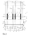
- the transport device 5 shown in FIGS. 1 and 2 is shown purely schematically, is of a known type and therefore not to be described in more detail here.
- Means this transport device 5 can workpieces 3, here e.g. Moldings or profile boards, with one towards the arrows 30 pointing direction of work under the applicator roller 2 are guided through and supported.
- the Application roller 2 is transverse to the working direction 30 by one Rotation axis 20 rotatably mounted. In her to the inlet side the area facing the device 1 is parallel to the Applicator roller 2 at a small, adjustable distance of which a metering roller 24 is arranged. It is used for Distribution of the at least one pipeline 22 from coating material 23 that can be fed in above over the entire Length of the application roller 2.
- the metering roller 24 produces depending on their distance from the application roller 2 one Predefinable layer thickness of the coating material 23 the scope of the application roller 2 and thus determines the Thickness of the coating material 23 on the workpiece 3.
- the device 1 provided with coating material 23 can, is seen in the working direction 30 behind the applicator roller 2 the arrangement of several application elements 4 provided.
- the illustrated embodiment of the device 1 consist of the application elements 4 each Disc on its circumference with a brush-like Bristle trim 42 is provided.
- the application elements 4 sit here on a common shaft 14 and are around an axis of rotation 40, which here is parallel to the axis of rotation 20 the application roller 2 runs in the direction of the arrow 41 optionally in one or the other direction of rotation drivable.
- drive motor provided for this, e.g. one in Figures 1 and 2 Not shown drive motor provided.
- the wave 14 and the application elements 4 are suitable, Holders not shown here held and in their position relative to the application roller 2 and relative to the workpiece 3 adjustable and lockable.
- the positioning the application elements 4 is such that they are in operation the device 1 from the applicator roller 2 there Remove remaining coating material 23, namely in the peripheral areas of the application roller 2, which over the deeper surface areas 33 of the workpiece to run.
- the by means of the application elements 4, here by means of the attached bristle trim 42 from the Application roller 2 is removed coating material 23 by rotating the application elements 4 downwards transported and on the previously not by the application roller 2 coated edge surface areas offset downwards 33 of the workpieces 3 transferred and passed through the bristle trim 42 and smoothed.
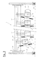
- Figure 3 of the drawing shows the device 1 in a modified version, now in a front view of the Inlet side of the device 1.
- Figure 3 illustrates particularly the arrangement of several Application elements 4 side by side, the number of Application elements 4 the respective need and size the device 1 chosen and determined accordingly can be.
- every application element has 4 the shape of a disc with bristle trimmings on its circumference 42 has.
- Each application element 4 is about an axis of rotation coinciding with its central axis 40 can be driven in rotation, for which purpose each application element 4 here in contrast to the example described above its own drive motor 43, preferably a continuously variable one adjustable pneumatic or electric motor.
- all drive motors are 43 via a support arm 45 on a common Crossbar 47 supported. Between the support arm 45 and the housing of the drive motor 43 is located there is a swivel joint hidden in the drawing with a pivot axis 44, which is perpendicular to Axis of rotation of the application elements 4 and parallel to Working direction 30 runs according to Figure 1.
- Each application element 4 is composed of holding arms 45 with its drive motor 43 in the direction of the movement arrow 45 'in height, i.e. at a distance from it Workpiece surface, adjustable and in the desired Height can be set. Another individual adjustment each application element 4 together with the drive motor 43 and support arm 45 is in the transverse direction 46 'along one in the crossbar 47 provided guide 46 possible. Finally, what is not visible in the drawing is an individual adjustment of each application element 4 in a direction perpendicular to the plane of the drawing, in terms of its distance from the applicator roller 2, provided.
- the crossbar 47 with all the application elements attached to it 4 is overall in the direction of the movement arrow 48 'height adjustable and lockable. This is the crossbar 47 left and right on one or several stands 48 held and guided.
- the stands 48 in turn are at their lower end on two parallel ones Rails 49 in their longitudinal direction, i.e. in a Direction perpendicular to the plane of the drawing of Figure 3, movable. These rails 49 expediently run on both sides the transport device shown in Figures 1 and 2 5 next to this parallel to the working direction 30 the device 1.
- the multiple adjustment options make it an optimal one Adaptation and alignment of each individual application element 4 to one or more to be coated Workpieces 3 possible.
- all application elements 4 can be adjusted together, for example when access to a device located in the device 1 Workpiece 3 is required from the outside or an exchange of application elements 4 should.
Landscapes
- Coating Apparatus (AREA)
- Application Of Or Painting With Fluid Materials (AREA)
Applications Claiming Priority (2)
| Application Number | Priority Date | Filing Date | Title |
|---|---|---|---|
| DE19851925A DE19851925A1 (de) | 1998-11-11 | 1998-11-11 | Vorrichtung zur Applizierung eines flüssigen und/oder pastösen Beschichtungsstoffs auf Oberflächen von Werkstücken |
| DE19851925 | 1998-11-11 |
Publications (3)
| Publication Number | Publication Date |
|---|---|
| EP1002586A2 true EP1002586A2 (fr) | 2000-05-24 |
| EP1002586A3 EP1002586A3 (fr) | 2001-11-28 |
| EP1002586B1 EP1002586B1 (fr) | 2005-12-21 |
Family
ID=7887377
Family Applications (1)
| Application Number | Title | Priority Date | Filing Date |
|---|---|---|---|
| EP99121383A Expired - Lifetime EP1002586B1 (fr) | 1998-11-11 | 1999-10-27 | Dispositif d'application de revêtements liquides ou pâteux à des pièces |
Country Status (4)
| Country | Link |
|---|---|
| EP (1) | EP1002586B1 (fr) |
| AT (1) | ATE313387T1 (fr) |
| DE (2) | DE19851925A1 (fr) |
| NO (1) | NO995490L (fr) |
Cited By (1)
| Publication number | Priority date | Publication date | Assignee | Title |
|---|---|---|---|---|
| CN109513566A (zh) * | 2018-12-18 | 2019-03-26 | 湖南固虹机械制造有限公司 | 一种树脂瓦均匀曲面滚涂装置 |
Citations (2)
| Publication number | Priority date | Publication date | Assignee | Title |
|---|---|---|---|---|
| DE8306769U1 (de) | 1983-03-09 | 1983-09-08 | Theodor Hymmen Kg, 4800 Bielefeld | Vorrichtung zum auftragen und glaetten von fluessigen massen auf durchlaufende plattenfoermige werkstuecke |
| DE4327421A1 (de) | 1993-08-14 | 1995-02-16 | Georgios Lukidis | Vorrichtung zum Einfärben von strukturierten, flächigen Teilen |
Family Cites Families (4)
| Publication number | Priority date | Publication date | Assignee | Title |
|---|---|---|---|---|
| FR2195395A1 (en) * | 1972-08-10 | 1974-03-08 | Alpma Alpenland Masch | Rotary cylindrical brush cheese coater - with deflectors so that one brush transverse to conveyor coats top and two sides |
| FR2325436A1 (fr) * | 1975-09-29 | 1977-04-22 | Durand Wayland Inc | Machine d'enduction |
| NL9302225A (nl) * | 1993-12-21 | 1995-07-17 | Elten Systems Bv | Werkwijze en inrichting voor het schmieren van kazen. |
| EP0916410A1 (fr) * | 1997-11-14 | 1999-05-19 | Akzo Nobel N.V. | Procédé et appareil d'encollage |
-
1998
- 1998-11-11 DE DE19851925A patent/DE19851925A1/de not_active Withdrawn
-
1999
- 1999-10-27 EP EP99121383A patent/EP1002586B1/fr not_active Expired - Lifetime
- 1999-10-27 AT AT99121383T patent/ATE313387T1/de not_active IP Right Cessation
- 1999-10-27 DE DE59912958T patent/DE59912958D1/de not_active Expired - Fee Related
- 1999-11-10 NO NO995490A patent/NO995490L/no not_active Application Discontinuation
Patent Citations (2)
| Publication number | Priority date | Publication date | Assignee | Title |
|---|---|---|---|---|
| DE8306769U1 (de) | 1983-03-09 | 1983-09-08 | Theodor Hymmen Kg, 4800 Bielefeld | Vorrichtung zum auftragen und glaetten von fluessigen massen auf durchlaufende plattenfoermige werkstuecke |
| DE4327421A1 (de) | 1993-08-14 | 1995-02-16 | Georgios Lukidis | Vorrichtung zum Einfärben von strukturierten, flächigen Teilen |
Cited By (2)
| Publication number | Priority date | Publication date | Assignee | Title |
|---|---|---|---|---|
| CN109513566A (zh) * | 2018-12-18 | 2019-03-26 | 湖南固虹机械制造有限公司 | 一种树脂瓦均匀曲面滚涂装置 |
| CN109513566B (zh) * | 2018-12-18 | 2024-04-02 | 湖南固虹机械制造有限公司 | 一种树脂瓦均匀曲面滚涂装置 |
Also Published As
| Publication number | Publication date |
|---|---|
| EP1002586A3 (fr) | 2001-11-28 |
| EP1002586B1 (fr) | 2005-12-21 |
| NO995490L (no) | 2000-05-12 |
| NO995490D0 (no) | 1999-11-10 |
| ATE313387T1 (de) | 2006-01-15 |
| DE59912958D1 (de) | 2006-01-26 |
| DE19851925A1 (de) | 2000-05-25 |
Similar Documents
| Publication | Publication Date | Title |
|---|---|---|
| DE3927680C2 (de) | Auftragsvorrichtung | |
| EP3049198B2 (fr) | Dispositif de guidage de bandes métalliques avec des corps d'usure | |
| DE1750580C3 (de) | Vorrichtung zum Aufbringen einer Thermoplast-Sperrschicht auf Teile der Gewinde von Kopfschrauben | |
| DE2217621C3 (de) | Vorrichtung zum Aufbringen eines Stranges in Zickzackform auf eine antreibbare Aufbautrommel | |
| DE3145151C2 (de) | Antreibbare Walze zum Überschleifen oder Polieren der Oberfläche einer Fahrzeugkarosserie oder dergleichen | |
| EP1123164B1 (fr) | Dispositif pour appliquer et/ou repartir des substances liquides ou pateuses pour recouvrir des surfaces | |
| EP1002586B1 (fr) | Dispositif d'application de revêtements liquides ou pâteux à des pièces | |
| DE2840803A1 (de) | Lackiereinrichtung | |
| DE69330471T2 (de) | Gerät zum Streuen von Material | |
| DE4129743C1 (fr) | ||
| DE19827712A1 (de) | Vorrichtung zum direkten oder indirekten Auftragen eines flüssigen oder pastösen Auftragsmediums auf eine laufende Materialbahn | |
| EP1808237B1 (fr) | Appareil de revêtement de bandes | |
| EP0728241B1 (fr) | Mecanisme permettant d'appliquer directement ou indirectement une substance sous forme de liquide ou de pate sur une bande de materiau en mouvement | |
| DE202009001870U1 (de) | Handbetätigte Vorrichtung zum Verteilen einer Auftragsmasse auf einer Tragfläche | |
| EP0120482B1 (fr) | Dispositif pour appliquer une couche d'un matériau céramique fin sur un porteur | |
| DE29820099U1 (de) | Vorrichtung zur Applizierung eines flüssigen und/oder pastösen Beschichtungsstoffs auf Oberflächen von Werkstücken | |
| DE3822077C2 (de) | Vorrichtung und ihre Verwendung zum Auftragen eines zähflüssigen Klebers auf ausgedehnte Flächen | |
| DE102004016507B4 (de) | Vorrichtung zum Egalisieren von auf einen Streubandförderer aufgestreutem Streugut | |
| DE7538002U (de) | Auftragmaschine zum auftragen zaehfluessiger medien, wie leim, lack ect. in form eines filmes auf ebene werkstueckflaechen | |
| EP0876978B1 (fr) | Dispositif pour gondoler du matériau en couche, spécialment du papier | |
| DE102004016687B4 (de) | Vorrichtung zum Andrücken einer Materialbahn | |
| DE3115818C2 (fr) | ||
| DE202005008623U1 (de) | Einrichtung zum Schleifen und/oder Polieren des Kantenbereiches eines plattenförmigen Werkstückes | |
| EP3666459A1 (fr) | Procédé de dressage d'une vis de rectification rotative | |
| DE3934986A1 (de) | Vorrichtung zum beschichten einer um eine gegenwalze gefuehrten materialbahn |
Legal Events
| Date | Code | Title | Description |
|---|---|---|---|
| PUAI | Public reference made under article 153(3) epc to a published international application that has entered the european phase |
Free format text: ORIGINAL CODE: 0009012 |
|
| AK | Designated contracting states |
Kind code of ref document: A2 Designated state(s): AT BE CH CY DE DK ES FI FR GB GR IE IT LI LU MC NL PT SE |
|
| AX | Request for extension of the european patent |
Free format text: AL;LT;LV;MK;RO;SI |
|
| PUAL | Search report despatched |
Free format text: ORIGINAL CODE: 0009013 |
|
| AK | Designated contracting states |
Kind code of ref document: A3 Designated state(s): AT BE CH CY DE DK ES FI FR GB GR IE IT LI LU MC NL PT SE |
|
| AX | Request for extension of the european patent |
Free format text: AL;LT;LV;MK;RO;SI |
|
| RAP1 | Party data changed (applicant data changed or rights of an application transferred) |
Owner name: SCHEIWE, PETER |
|
| RAP1 | Party data changed (applicant data changed or rights of an application transferred) |
Owner name: BALTESCHWILER AG Owner name: SCHEIWE, PETER |
|
| AKX | Designation fees paid | ||
| REG | Reference to a national code |
Ref country code: DE Ref legal event code: 8566 |
|
| 17P | Request for examination filed |
Effective date: 20020731 |
|
| RBV | Designated contracting states (corrected) |
Designated state(s): AT BE CH CY DE DK ES FI FR GB GR IE IT LI LU MC NL PT SE |
|
| GRAP | Despatch of communication of intention to grant a patent |
Free format text: ORIGINAL CODE: EPIDOSNIGR1 |
|
| GRAS | Grant fee paid |
Free format text: ORIGINAL CODE: EPIDOSNIGR3 |
|
| GRAA | (expected) grant |
Free format text: ORIGINAL CODE: 0009210 |
|
| RIN1 | Information on inventor provided before grant (corrected) |
Inventor name: SCHULZE TERTILT, KLAUS Inventor name: SALAMONOWICZ, PAWEL |
|
| AK | Designated contracting states |
Kind code of ref document: B1 Designated state(s): AT BE CH CY DE DK ES FI FR GB GR IE IT LI LU MC NL PT SE |
|
| PG25 | Lapsed in a contracting state [announced via postgrant information from national office to epo] |
Ref country code: IT Free format text: LAPSE BECAUSE OF FAILURE TO SUBMIT A TRANSLATION OF THE DESCRIPTION OR TO PAY THE FEE WITHIN THE PRESCRIBED TIME-LIMIT;WARNING: LAPSES OF ITALIAN PATENTS WITH EFFECTIVE DATE BEFORE 2007 MAY HAVE OCCURRED AT ANY TIME BEFORE 2007. THE CORRECT EFFECTIVE DATE MAY BE DIFFERENT FROM THE ONE RECORDED. Effective date: 20051221 Ref country code: IE Free format text: LAPSE BECAUSE OF FAILURE TO SUBMIT A TRANSLATION OF THE DESCRIPTION OR TO PAY THE FEE WITHIN THE PRESCRIBED TIME-LIMIT Effective date: 20051221 Ref country code: GB Free format text: LAPSE BECAUSE OF FAILURE TO SUBMIT A TRANSLATION OF THE DESCRIPTION OR TO PAY THE FEE WITHIN THE PRESCRIBED TIME-LIMIT Effective date: 20051221 |
|
| REG | Reference to a national code |
Ref country code: GB Ref legal event code: FG4D Free format text: NOT ENGLISH |
|
| REG | Reference to a national code |
Ref country code: CH Ref legal event code: EP |
|
| REG | Reference to a national code |
Ref country code: IE Ref legal event code: FG4D Free format text: LANGUAGE OF EP DOCUMENT: GERMAN |
|
| REF | Corresponds to: |
Ref document number: 59912958 Country of ref document: DE Date of ref document: 20060126 Kind code of ref document: P |
|
| PG25 | Lapsed in a contracting state [announced via postgrant information from national office to epo] |
Ref country code: GR Free format text: LAPSE BECAUSE OF FAILURE TO SUBMIT A TRANSLATION OF THE DESCRIPTION OR TO PAY THE FEE WITHIN THE PRESCRIBED TIME-LIMIT Effective date: 20060321 Ref country code: DK Free format text: LAPSE BECAUSE OF FAILURE TO SUBMIT A TRANSLATION OF THE DESCRIPTION OR TO PAY THE FEE WITHIN THE PRESCRIBED TIME-LIMIT Effective date: 20060321 |
|
| PG25 | Lapsed in a contracting state [announced via postgrant information from national office to epo] |
Ref country code: ES Free format text: LAPSE BECAUSE OF FAILURE TO SUBMIT A TRANSLATION OF THE DESCRIPTION OR TO PAY THE FEE WITHIN THE PRESCRIBED TIME-LIMIT Effective date: 20060401 |
|
| REG | Reference to a national code |
Ref country code: SE Ref legal event code: TRGR |
|
| PG25 | Lapsed in a contracting state [announced via postgrant information from national office to epo] |
Ref country code: PT Free format text: LAPSE BECAUSE OF FAILURE TO SUBMIT A TRANSLATION OF THE DESCRIPTION OR TO PAY THE FEE WITHIN THE PRESCRIBED TIME-LIMIT Effective date: 20060522 |
|
| REG | Reference to a national code |
Ref country code: CH Ref legal event code: NV Representative=s name: LUCHS & PARTNER PATENTANWAELTE |
|
| GBV | Gb: ep patent (uk) treated as always having been void in accordance with gb section 77(7)/1977 [no translation filed] |
Effective date: 20051221 |
|
| REG | Reference to a national code |
Ref country code: IE Ref legal event code: FD4D |
|
| PG25 | Lapsed in a contracting state [announced via postgrant information from national office to epo] |
Ref country code: MC Free format text: LAPSE BECAUSE OF NON-PAYMENT OF DUE FEES Effective date: 20061031 |
|
| PLBE | No opposition filed within time limit |
Free format text: ORIGINAL CODE: 0009261 |
|
| STAA | Information on the status of an ep patent application or granted ep patent |
Free format text: STATUS: NO OPPOSITION FILED WITHIN TIME LIMIT |
|
| 26N | No opposition filed |
Effective date: 20060922 |
|
| EN | Fr: translation not filed | ||
| BERE | Be: lapsed |
Owner name: BALTESCHWILER A.G. Effective date: 20061031 Owner name: SCHEIWE, PETER Effective date: 20061031 |
|
| PG25 | Lapsed in a contracting state [announced via postgrant information from national office to epo] |
Ref country code: FR Free format text: LAPSE BECAUSE OF FAILURE TO SUBMIT A TRANSLATION OF THE DESCRIPTION OR TO PAY THE FEE WITHIN THE PRESCRIBED TIME-LIMIT Effective date: 20070209 |
|
| PG25 | Lapsed in a contracting state [announced via postgrant information from national office to epo] |
Ref country code: LU Free format text: LAPSE BECAUSE OF NON-PAYMENT OF DUE FEES Effective date: 20061027 |
|
| PG25 | Lapsed in a contracting state [announced via postgrant information from national office to epo] |
Ref country code: FR Free format text: LAPSE BECAUSE OF FAILURE TO SUBMIT A TRANSLATION OF THE DESCRIPTION OR TO PAY THE FEE WITHIN THE PRESCRIBED TIME-LIMIT Effective date: 20051221 Ref country code: CY Free format text: LAPSE BECAUSE OF FAILURE TO SUBMIT A TRANSLATION OF THE DESCRIPTION OR TO PAY THE FEE WITHIN THE PRESCRIBED TIME-LIMIT Effective date: 20051221 |
|
| PGFP | Annual fee paid to national office [announced via postgrant information from national office to epo] |
Ref country code: NL Payment date: 20081026 Year of fee payment: 10 |
|
| PGFP | Annual fee paid to national office [announced via postgrant information from national office to epo] |
Ref country code: DE Payment date: 20081204 Year of fee payment: 10 Ref country code: CH Payment date: 20081031 Year of fee payment: 10 |
|
| PGFP | Annual fee paid to national office [announced via postgrant information from national office to epo] |
Ref country code: FI Payment date: 20081029 Year of fee payment: 10 Ref country code: AT Payment date: 20081029 Year of fee payment: 10 |
|
| PGFP | Annual fee paid to national office [announced via postgrant information from national office to epo] |
Ref country code: SE Payment date: 20081031 Year of fee payment: 10 |
|
| PG25 | Lapsed in a contracting state [announced via postgrant information from national office to epo] |
Ref country code: BE Free format text: LAPSE BECAUSE OF FAILURE TO SUBMIT A TRANSLATION OF THE DESCRIPTION OR TO PAY THE FEE WITHIN THE PRESCRIBED TIME-LIMIT Effective date: 20061031 |
|
| REG | Reference to a national code |
Ref country code: NL Ref legal event code: V1 Effective date: 20100501 |
|
| REG | Reference to a national code |
Ref country code: CH Ref legal event code: PL |
|
| EUG | Se: european patent has lapsed | ||
| PG25 | Lapsed in a contracting state [announced via postgrant information from national office to epo] |
Ref country code: NL Free format text: LAPSE BECAUSE OF NON-PAYMENT OF DUE FEES Effective date: 20100501 Ref country code: DE Free format text: LAPSE BECAUSE OF NON-PAYMENT OF DUE FEES Effective date: 20100501 |
|
| PG25 | Lapsed in a contracting state [announced via postgrant information from national office to epo] |
Ref country code: FI Free format text: LAPSE BECAUSE OF NON-PAYMENT OF DUE FEES Effective date: 20091027 Ref country code: AT Free format text: LAPSE BECAUSE OF NON-PAYMENT OF DUE FEES Effective date: 20091027 |
|
| PG25 | Lapsed in a contracting state [announced via postgrant information from national office to epo] |
Ref country code: LI Free format text: LAPSE BECAUSE OF NON-PAYMENT OF DUE FEES Effective date: 20091031 Ref country code: CH Free format text: LAPSE BECAUSE OF NON-PAYMENT OF DUE FEES Effective date: 20091031 |
|
| PG25 | Lapsed in a contracting state [announced via postgrant information from national office to epo] |
Ref country code: SE Free format text: LAPSE BECAUSE OF NON-PAYMENT OF DUE FEES Effective date: 20091028 |