EP1002600B1 - Tube plongeur pour introduire un métal fondu, dans une coquille pour la coulée en continue de plaques fines - Google Patents
Tube plongeur pour introduire un métal fondu, dans une coquille pour la coulée en continue de plaques fines Download PDFInfo
- Publication number
- EP1002600B1 EP1002600B1 EP99122176A EP99122176A EP1002600B1 EP 1002600 B1 EP1002600 B1 EP 1002600B1 EP 99122176 A EP99122176 A EP 99122176A EP 99122176 A EP99122176 A EP 99122176A EP 1002600 B1 EP1002600 B1 EP 1002600B1
- Authority
- EP
- European Patent Office
- Prior art keywords
- flow
- height
- contour element
- pouring pipe
- immersion pouring
- Prior art date
- Legal status (The legal status is an assumption and is not a legal conclusion. Google has not performed a legal analysis and makes no representation as to the accuracy of the status listed.)
- Expired - Lifetime
Links
- 238000009749 continuous casting Methods 0.000 title claims abstract description 4
- 239000000463 material Substances 0.000 title 1
- 239000002184 metal Substances 0.000 title 1
- 238000007654 immersion Methods 0.000 claims abstract description 15
- 239000007787 solid Substances 0.000 claims abstract description 7
- 230000007704 transition Effects 0.000 claims description 3
- 230000015572 biosynthetic process Effects 0.000 claims description 2
- 239000011159 matrix material Substances 0.000 claims description 2
- 239000000161 steel melt Substances 0.000 claims 1
- 238000005266 casting Methods 0.000 description 6
- 239000000155 melt Substances 0.000 description 6
- 229910000831 Steel Inorganic materials 0.000 description 2
- 230000001154 acute effect Effects 0.000 description 2
- 239000010959 steel Substances 0.000 description 2
- 206010038743 Restlessness Diseases 0.000 description 1
- 230000002411 adverse Effects 0.000 description 1
- 238000007598 dipping method Methods 0.000 description 1
- 230000002349 favourable effect Effects 0.000 description 1
- 238000002386 leaching Methods 0.000 description 1
- 238000004519 manufacturing process Methods 0.000 description 1
- 230000008018 melting Effects 0.000 description 1
- 238000002844 melting Methods 0.000 description 1
- 238000000465 moulding Methods 0.000 description 1
- 238000000926 separation method Methods 0.000 description 1
- 239000002689 soil Substances 0.000 description 1
- 230000006641 stabilisation Effects 0.000 description 1
- 238000011105 stabilization Methods 0.000 description 1
Images


Classifications
-
- B—PERFORMING OPERATIONS; TRANSPORTING
- B22—CASTING; POWDER METALLURGY
- B22D—CASTING OF METALS; CASTING OF OTHER SUBSTANCES BY THE SAME PROCESSES OR DEVICES
- B22D41/00—Casting melt-holding vessels, e.g. ladles, tundishes, cups or the like
- B22D41/50—Pouring-nozzles
Definitions
- the invention relates to a submersible pouring tube for introducing melt, in particular Molten steel, from a casting or intermediate container in one with Breittimeund Narrow-side walls formed mold for continuous casting of particular Flat products, wherein the Tauchg screenrohr designed as a flow channel Pipe having, which with a wedge-shaped contour element and at least a flow divider with two opposite to the narrow side walls Outlet openings is formed.
- Immersion tubes ensure a uniform and low-turbulence in the mold Distribution of the melt.
- a submersible pouring tube must be designed to be a restless one G manaptier in the form of a pulsating up and down movement or a Wave motion within the mold is avoided.
- These specifications must in particular dipping pipes for so-called thin slab formats, with a thickness between 30 and 100 mm, meet.
- a Tauchg tellrohr for a thin slab which consists of a lower tube piece, which in the direction of the Narrow sidewalls of the mold are extended in cross-section and at the lower end with a centrally located bottom piece leaving outlet openings is provided for the melt.
- the inner wall of the cross-section widening Part of the submersible pouring tube forms together with the opposite Wall portions of the bottom piece flow channels whose axes with the Tauchg phonerohrachachse include a certain angle between 10 and 22 Degree is.
- This Tauchg phonerohr has a much greater width than thickness on.
- the outlet openings from the Tauchg screenrohr are narrowed like a nozzle.
- the present invention is based on the recognition that it is in the flow transition from the outlet openings of the Tauchg cordrohres in the mold not a free flow, but rather a Umströmvorgang is. This is the effective flow around the length of the central Contour element of the pouring tube of decisive importance, d. H. the longer the effective length of the soil element, the more stable the flow division and leadership.
- the object of the invention is the above-mentioned finding in a Tauchg tellrohr the genus mentioned above constructively realize so that a stable flow division is ensured by the dip tube and a largely low-turbulence inflow of the melt from the immersion nozzle in the Melting sump of the mold can be done.
- the object is achieved with a submersible pouring tube of the type mentioned with the invention in that the contour element with a merging into one another merging a massive, opposite wall portions connecting part with the height (H 1 ) and a pair above the same outgoing from this Strömungsmaschinem with in Direction of the X-axis provided height (H 2 ) is formed projecting projecting from the wall portions in the pipe section of the flow channel without firm connection with the opposite wall areas and the height H 1 of the contour element is greater together with the height H 2 of the flow divider as the height L 1 of an outlet opening.
- the contour element is an opposite wall portions of the pipe section connecting solid molding with the height H 1 , resulting from the fact that it preferably has in the direction of the outlet openings the spatial shape of a tapered to opposite sides of the wedge.
- a particularly preferred embodiment of the dip tube is achieved in that the contour element in the direction of its outlet openings has the spatial shape of a concave, in particular a polynomial function at least second order defining curve.
- the further advantageous embodiment of the invention further provides that the flow dividers are designed as flow guide with rectangular or trapezoidal cross section whose width b and / or height h over the length L of the pipe section is variable, and that the flow guide the height L 1 of the outlet openings overtop.
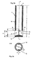
- FIG. 1 shows the immersion casting tube 1 for introducing molten steel from a Casting or intermediate container 3 in a mold 5, in particular for casting Thin slabs spatially through broad side walls 14 and narrow side walls 15 is limited.
- the reaching into the melt pool of the mold 5 Tauchgitrohr 1 shows a lower tube piece with two outlet openings 8, 8 ', which are in Direction of the narrow side walls 15 of the mold 5 show.
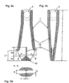
- Figure 2a shows the inventive design of the Tauchg screenrohres 1, after which the lower tube piece a solid contour element 10 and flow divider 12th and the height H1 + H2, which is the flow distribution in the flow channel 2 of the pipe section, is greater than the height L1 of the outlet opening 8, 8 '.
- the contour element 10 consists of a solid, opposite wall areas connecting part with the height H1.
- flow guide 12 are shown, starting from opposite wall portions in the flow channel 2 of the pipe section. 1 protrude and stabilize the flow jet.
- the widths b and / or the height h the flow guide 12 can vary over the length of the dip tube L. be.
- Figures 4a to 4c is a particularly favorable form of massive Contour element 10 shown, with the shape of a tapered to both sides Wedge, preferably with a concave, via a polynomial function at least second order waveform to be defined
Landscapes
- Engineering & Computer Science (AREA)
- Mechanical Engineering (AREA)
- Continuous Casting (AREA)
- Casting Support Devices, Ladles, And Melt Control Thereby (AREA)
Claims (8)
- Tube plongeur (1) pour introduire un métal fondu, en particulier de l'acier, à partir d'un réservoir de coulée ou d'un réservoir intermédiaire (3) dans une coquille ou lingotière (5), constituée de parois larges (14) et de parois étroites (15) pour la coulée continue de produits plats en particulier, du type dans lequel le tube plongeur (1) présente une partie tubulaire (11), sous la forme d'un canal d'écoulement ou de flux et également conformée avec un élément à profil formant contour (10), en forme de coin, coopérant avec au moins un diviseur de flux (12) avec deux ouvertures de sortie (8,8') opposées en direction des parois étroites (15),
caractérisé en ce que l'élément à profil formant contour (10) est conformé par la combinaison, selon un profil de recouvrement mutuel, d'une partie (10), de hauteur (H1) et reliant des zones de parois opposées, et d'une paire de diviseurs de flux (12), disposés sur une hauteur (H2), dans le sens de l'axe X- X, au- dessus de ladite partie (10) et s'élevant en saillie à partir desdites zones de paroi à l'intérieur de la partie tubulaire (11) dudit canal d'écoulement, sans liaison solide avec les zones opposées de paroi, et en ce que la somme de la hauteur (H1) de l'élément à profil formant contour (10) et de la hauteur (H2) des diviseurs de flux (12) est supérieure à la hauteur (L1) d'une ouverture de sortie (8,8'). - Tube plongeur selon la revendication 1, caractérisé en ce que les diviseurs de flux (12) se dressent dans la partie tubulaire (11), sans formation d'une liaison solide des zones de paroi antagonistes.
- Tube plongeur selon la revendication 1 ou 2, caractérisé en ce que l'élément à profil formant contour (10) est en forme de coin, dont le profil va en diminuant ou en se resserrant sur les côtés opposés.
- Tube plongeur selon l'une des revendications 1 à 3, caractérisé en ce que l'élément à profil formant contour (10) présente, en direction des ouvertures de sortie (8,8'), un profil en forme de courbe concave définie, de préférence une fonction polynomiale de puissance au moins égale à deux.
- Tube plongeur selon l'une au moins des revendications 1 à 4, caractérisé en ce que les diviseurs de flux (12) sont conformés comme des dispositifs de guidage de flux, de section transversale rectangulaire ou trapézoïdale, dont la largeur (b) et/ ou la hauteur (h) est variable sur la longueur (L) de la partie tubulaire (11).
- Tube plongeur selon l'une au moins des revendications 1 à 5, caractérisé en ce que les dispositifs de guidage de flux (12) dépassent, en hauteur, la hauteur (L1) des ouvertures de sortie (8,8').
- Tube plongeur selon l'une au moins des revendications 1 à 6, caractérisé en ce que l'élément à profil formant contour (10), associé aux dispositifs de guidage de flux (12), présente des zones arrondies sur ses arêtes et/ou portions de surface de transition.
- Tube plongeur selon l'une au moins des revendications 1 à 7, caractérisé en ce que les dispositifs de guidage de flux (12), associés à l'élément à profil formant contour (10), constituent soit un élément unique interchangeable, soit un élément encastré ou noyé dans la matrice dudit élément à profil formant contour (10).
Applications Claiming Priority (4)
| Application Number | Priority Date | Filing Date | Title |
|---|---|---|---|
| DE19853723 | 1998-11-20 | ||
| DE19853723 | 1998-11-20 | ||
| DE19908346A DE19908346A1 (de) | 1998-11-20 | 1999-02-26 | Tauchgießrohr zum Einleiten von Schmelze in eine Kokille zum Stranggießen insbesondere von Flachprodukten |
| DE19908346 | 1999-02-26 |
Publications (3)
| Publication Number | Publication Date |
|---|---|
| EP1002600A2 EP1002600A2 (fr) | 2000-05-24 |
| EP1002600A3 EP1002600A3 (fr) | 2001-04-04 |
| EP1002600B1 true EP1002600B1 (fr) | 2004-01-21 |
Family
ID=26050298
Family Applications (1)
| Application Number | Title | Priority Date | Filing Date |
|---|---|---|---|
| EP99122176A Expired - Lifetime EP1002600B1 (fr) | 1998-11-20 | 1999-11-05 | Tube plongeur pour introduire un métal fondu, dans une coquille pour la coulée en continue de plaques fines |
Country Status (3)
| Country | Link |
|---|---|
| EP (1) | EP1002600B1 (fr) |
| AT (1) | ATE258088T1 (fr) |
| ES (1) | ES2214796T3 (fr) |
Families Citing this family (2)
| Publication number | Priority date | Publication date | Assignee | Title |
|---|---|---|---|---|
| RU2679664C2 (ru) * | 2014-06-11 | 2019-02-12 | Арведи Стил Энджиниринг С.П.А. | Стакан для литья тонких слябов для распределения расплавленного металла с высоким расходом |
| CN118682117A (zh) * | 2023-03-21 | 2024-09-24 | 宝山钢铁股份有限公司 | 一种防卷渣的浸入式水口及应用方法 |
Family Cites Families (5)
| Publication number | Priority date | Publication date | Assignee | Title |
|---|---|---|---|---|
| DE4032624A1 (de) * | 1990-10-15 | 1992-04-16 | Schloemann Siemag Ag | Tauchgiessrohr zum einleiten von stahlschmelze in eine stranggiesskokille |
| DE4142447C3 (de) * | 1991-06-21 | 1999-09-09 | Mannesmann Ag | Tauchgießrohr - Dünnbramme |
| US5785880A (en) * | 1994-03-31 | 1998-07-28 | Vesuvius Usa | Submerged entry nozzle |
| IT1267299B1 (it) * | 1994-09-30 | 1997-01-28 | Danieli Off Mecc | Scaricatore per cristallizzatore per colata continua di bramme sottili |
| IT1284035B1 (it) * | 1996-06-19 | 1998-05-08 | Giovanni Arvedi | Tuffante per la colata continua di bramme sottili |
-
1999
- 1999-11-05 EP EP99122176A patent/EP1002600B1/fr not_active Expired - Lifetime
- 1999-11-05 ES ES99122176T patent/ES2214796T3/es not_active Expired - Lifetime
- 1999-11-05 AT AT99122176T patent/ATE258088T1/de active
Also Published As
| Publication number | Publication date |
|---|---|
| ATE258088T1 (de) | 2004-02-15 |
| EP1002600A2 (fr) | 2000-05-24 |
| ES2214796T3 (es) | 2004-09-16 |
| EP1002600A3 (fr) | 2001-04-04 |
Similar Documents
| Publication | Publication Date | Title |
|---|---|---|
| EP0254909B1 (fr) | Busette de coulée réfractaire | |
| DE3501422C2 (fr) | ||
| DE69803196T2 (de) | Stranggiesskokille für stahlbrammen | |
| WO1993000191A1 (fr) | Busette de coulee par immersion pour brames minces | |
| DE4131829C2 (de) | Flüssigkeitsgekühlte Kokille für das Stranggießen von Strängen aus Stahl im Brammenformat | |
| EP0482423B1 (fr) | Tube plongeur de coulée pour l'introduction d'acier liquide dans une lingotière de coulée continue | |
| AT400935B (de) | Tauchgiessrohr | |
| DE3918228C2 (de) | Tauchgießrohr zum Einleiten von Stahlschmelze in eine Stranggießkokille | |
| DE2442915A1 (de) | Giessrohr mit geschlossenem boden und einander gegenueberliegenden seitlichen oeffnungen | |
| EP0230886A2 (fr) | Lingotière pour coulée continue de bande en acier | |
| EP1002600B1 (fr) | Tube plongeur pour introduire un métal fondu, dans une coquille pour la coulée en continue de plaques fines | |
| EP0865849A1 (fr) | Lingotière oscillante pour la coulée continue de brames | |
| WO1996011078A1 (fr) | Buse de coulee immergee | |
| EP0179364A2 (fr) | Lingotière de coulée continue pour billettes d'acier à section transversale polygonale | |
| DE2548585B2 (de) | Vorrichtung zum stranggiessen von stahl | |
| EP0900609B1 (fr) | Tube plongeur pour introduire un métal fondu, à partir d'un récipient de coulée ou un récipient intermédiaire, dans une coquille | |
| DE2318639C3 (de) | Gießrohr zum Eingießen von Stahl in eine Stranggießkokille | |
| DE2250048C3 (de) | Feuerfestes Gießrohr zum Stranggießen schmelzflüssiger Metalle, insbesondere Stahl | |
| DE19908346A1 (de) | Tauchgießrohr zum Einleiten von Schmelze in eine Kokille zum Stranggießen insbesondere von Flachprodukten | |
| DE3403892C2 (de) | Vorrichtung für die Einleitung von Metallschmelze, insbesondere von Stahlschmelze, in eine Stranggießkokille | |
| DE19715826A1 (de) | Tauchgießrohr für eine Dünnbrammen- bzw. Stahlbandgießkokille | |
| DE3638032C2 (fr) | ||
| DE10117097A1 (de) | Tauchgießrohr zum Einleiten von Stahlschmelze in eine Kokille oder in eine Zwei-Rollen-Gießmaschine | |
| DE4322948A1 (de) | Stranggießkokille zum Gießen von Dünnbrammen | |
| DE19503911A1 (de) | Anfahrkopf und Verfahren zum Angießen einer Stranggießanlage |
Legal Events
| Date | Code | Title | Description |
|---|---|---|---|
| PUAI | Public reference made under article 153(3) epc to a published international application that has entered the european phase |
Free format text: ORIGINAL CODE: 0009012 |
|
| 17P | Request for examination filed |
Effective date: 19991118 |
|
| AK | Designated contracting states |
Kind code of ref document: A2 Designated state(s): AT DE ES FR GB IT NL |
|
| AX | Request for extension of the european patent |
Free format text: AL;LT;LV;MK;RO;SI |
|
| PUAL | Search report despatched |
Free format text: ORIGINAL CODE: 0009013 |
|
| AK | Designated contracting states |
Kind code of ref document: A3 Designated state(s): AT BE CH CY DE DK ES FI FR GB GR IE IT LI LU MC NL PT SE |
|
| AX | Request for extension of the european patent |
Free format text: AL;LT;LV;MK;RO;SI |
|
| AKX | Designation fees paid |
Free format text: AT DE ES FR GB IT NL |
|
| 17Q | First examination report despatched |
Effective date: 20020926 |
|
| GRAP | Despatch of communication of intention to grant a patent |
Free format text: ORIGINAL CODE: EPIDOSNIGR1 |
|
| GRAS | Grant fee paid |
Free format text: ORIGINAL CODE: EPIDOSNIGR3 |
|
| GRAA | (expected) grant |
Free format text: ORIGINAL CODE: 0009210 |
|
| AK | Designated contracting states |
Kind code of ref document: B1 Designated state(s): AT DE ES FR GB IT NL |
|
| PG25 | Lapsed in a contracting state [announced via postgrant information from national office to epo] |
Ref country code: NL Free format text: LAPSE BECAUSE OF FAILURE TO SUBMIT A TRANSLATION OF THE DESCRIPTION OR TO PAY THE FEE WITHIN THE PRESCRIBED TIME-LIMIT Effective date: 20040121 Ref country code: FR Free format text: LAPSE BECAUSE OF FAILURE TO SUBMIT A TRANSLATION OF THE DESCRIPTION OR TO PAY THE FEE WITHIN THE PRESCRIBED TIME-LIMIT Effective date: 20040121 |
|
| REG | Reference to a national code |
Ref country code: GB Ref legal event code: FG4D Free format text: NOT ENGLISH |
|
| REF | Corresponds to: |
Ref document number: 59908363 Country of ref document: DE Date of ref document: 20040226 Kind code of ref document: P |
|
| GBT | Gb: translation of ep patent filed (gb section 77(6)(a)/1977) |
Effective date: 20040517 |
|
| NLV1 | Nl: lapsed or annulled due to failure to fulfill the requirements of art. 29p and 29m of the patents act | ||
| REG | Reference to a national code |
Ref country code: ES Ref legal event code: FG2A Ref document number: 2214796 Country of ref document: ES Kind code of ref document: T3 |
|
| PLBE | No opposition filed within time limit |
Free format text: ORIGINAL CODE: 0009261 |
|
| STAA | Information on the status of an ep patent application or granted ep patent |
Free format text: STATUS: NO OPPOSITION FILED WITHIN TIME LIMIT |
|
| 26N | No opposition filed |
Effective date: 20041022 |
|
| EN | Fr: translation not filed | ||
| EN | Fr: translation not filed | ||
| REG | Reference to a national code |
Ref country code: FR Ref legal event code: ERR Free format text: BOPI DE PUBLICATION N: 05/03 PAGES: 237 PARTIE DU BULLETIN CONCERNEE: BREVETS EUROPEENS DONT LA TRADUCTION N'A PAS ETE REMISE I'INPI IL Y A LIEU DE SUPPRIMER: LA MENTION DE LA NON REMISE. |
|
| PGFP | Annual fee paid to national office [announced via postgrant information from national office to epo] |
Ref country code: ES Payment date: 20121127 Year of fee payment: 14 Ref country code: GB Payment date: 20121120 Year of fee payment: 14 Ref country code: IT Payment date: 20121126 Year of fee payment: 14 |
|
| PGFP | Annual fee paid to national office [announced via postgrant information from national office to epo] |
Ref country code: AT Payment date: 20121113 Year of fee payment: 14 |
|
| REG | Reference to a national code |
Ref country code: AT Ref legal event code: MM01 Ref document number: 258088 Country of ref document: AT Kind code of ref document: T Effective date: 20131105 |
|
| GBPC | Gb: european patent ceased through non-payment of renewal fee |
Effective date: 20131105 |
|
| PG25 | Lapsed in a contracting state [announced via postgrant information from national office to epo] |
Ref country code: IT Free format text: LAPSE BECAUSE OF NON-PAYMENT OF DUE FEES Effective date: 20131105 Ref country code: AT Free format text: LAPSE BECAUSE OF NON-PAYMENT OF DUE FEES Effective date: 20131105 |
|
| PG25 | Lapsed in a contracting state [announced via postgrant information from national office to epo] |
Ref country code: GB Free format text: LAPSE BECAUSE OF NON-PAYMENT OF DUE FEES Effective date: 20131105 |
|
| REG | Reference to a national code |
Ref country code: ES Ref legal event code: FD2A Effective date: 20150507 |
|
| PG25 | Lapsed in a contracting state [announced via postgrant information from national office to epo] |
Ref country code: ES Free format text: LAPSE BECAUSE OF NON-PAYMENT OF DUE FEES Effective date: 20131106 |
|
| REG | Reference to a national code |
Ref country code: DE Ref legal event code: R082 Ref document number: 59908363 Country of ref document: DE Representative=s name: HEMMERICH & KOLLEGEN, DE Ref country code: DE Ref legal event code: R081 Ref document number: 59908363 Country of ref document: DE Owner name: SMS GROUP GMBH, DE Free format text: FORMER OWNER: SMS SIEMAG AKTIENGESELLSCHAFT, 40237 DUESSELDORF, DE |
|
| PGFP | Annual fee paid to national office [announced via postgrant information from national office to epo] |
Ref country code: DE Payment date: 20181120 Year of fee payment: 20 |
|
| REG | Reference to a national code |
Ref country code: DE Ref legal event code: R071 Ref document number: 59908363 Country of ref document: DE |