EP0482423B1 - Tube plongeur de coulée pour l'introduction d'acier liquide dans une lingotière de coulée continue - Google Patents
Tube plongeur de coulée pour l'introduction d'acier liquide dans une lingotière de coulée continue Download PDFInfo
- Publication number
- EP0482423B1 EP0482423B1 EP91117179A EP91117179A EP0482423B1 EP 0482423 B1 EP0482423 B1 EP 0482423B1 EP 91117179 A EP91117179 A EP 91117179A EP 91117179 A EP91117179 A EP 91117179A EP 0482423 B1 EP0482423 B1 EP 0482423B1
- Authority
- EP
- European Patent Office
- Prior art keywords
- outflow
- pouring tube
- immersion
- web
- tube according
- Prior art date
- Legal status (The legal status is an assumption and is not a legal conclusion. Google has not performed a legal analysis and makes no representation as to the accuracy of the status listed.)
- Revoked
Links
- 238000007654 immersion Methods 0.000 title claims abstract description 19
- 229910000831 Steel Inorganic materials 0.000 title claims abstract description 18
- 239000010959 steel Substances 0.000 title claims abstract description 18
- 238000005266 casting Methods 0.000 title claims abstract description 15
- 238000009749 continuous casting Methods 0.000 title claims abstract description 4
- 239000002184 metal Substances 0.000 claims abstract description 3
- 239000007788 liquid Substances 0.000 claims description 4
- 238000005406 washing Methods 0.000 description 4
- 238000009826 distribution Methods 0.000 description 3
- 241001295925 Gegenes Species 0.000 description 1
- 230000001154 acute effect Effects 0.000 description 1
- 230000015572 biosynthetic process Effects 0.000 description 1
- 230000002349 favourable effect Effects 0.000 description 1
- 238000009434 installation Methods 0.000 description 1
- 230000001788 irregular Effects 0.000 description 1
- 238000004519 manufacturing process Methods 0.000 description 1
- 238000005507 spraying Methods 0.000 description 1
- 230000007704 transition Effects 0.000 description 1
- 238000011144 upstream manufacturing Methods 0.000 description 1
Images

Classifications
-
- B—PERFORMING OPERATIONS; TRANSPORTING
- B22—CASTING; POWDER METALLURGY
- B22D—CASTING OF METALS; CASTING OF OTHER SUBSTANCES BY THE SAME PROCESSES OR DEVICES
- B22D41/00—Casting melt-holding vessels, e.g. ladles, tundishes, cups or the like
- B22D41/50—Pouring-nozzles
Definitions
- the invention relates to an immersion pouring tube for introducing molten metal, in particular liquid steel, into the pouring region of a continuous casting installation, consisting of an inflow part connected to a casting container and a flattened outflow part with surfaces located on a web for dividing the inflow flow into at least two partial flows and with surfaces for combining Partial flows in front of the outflow opening.
- a flattened end part with slot-like outlet openings and a base piece with a raised inner contour are arranged on the cylindrical tube part.
- the base piece has a greater extent in the direction of the outflow openings than the distance between the walls delimiting the outflow openings upwards.
- This well-known pouring tube has not grown with the required operational reliability and service life despite the complex production of the high stresses in continuous steel casting.
- the molten steel emerges from the narrow outflow openings with excessive kinetic energy, which leads to washing out of the still thin strand shell and the formation of a damming wave in front of the narrow side walls, particularly in a narrow steel strip casting mold.
- an irregular surface structure is formed due to the uneven flow distribution within the mold.
- the object of the invention is to provide a reliable immersion pouring tube for pouring molten steel into a mold, in particular for casting steel strips, whereby due to better flow distribution, a build-up wave in the surface of the bath surface and a washing out of the strand shell that is formed by the liquid steel are greatly reduced and a casting strand, in particular steel strip, is provided uniformly flawless surface is achieved.
- the spraying and baking of molten steel on the mold walls should be avoided during the casting process.
- the invention is based on the knowledge that the cause of an uneven, unstable melt distribution within the mold is too high and uneven exit velocity over the exit cross-sections.
- the object is achieved in that the outflow part has surfaces for diverting the partial flows up to opposite directions in front of the outflow opening.
- the outflow part has lateral guide surfaces, bottom surfaces and and the underside of the web above the outflow opening at a distance from the web.
- the width w of the outflow opening corresponds to at least twice the distance a of the web sliding surface from the floor.
- the width of the outflow part parallel to the wide walls is between 350 and 550 mm.
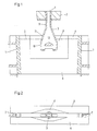
- FIG. 1 there is an immersion pouring tube 3 at the bottom outlet 1 of a casting container 2, the lower end of which extends into a steel strip casting mold 4 to below the casting level 5.
- the steel strip casting mold 4 consists of two cooled broad side walls 6 and two narrow side walls 7 arranged between them.
- the wide side walls 6 form an enlarged pouring area 8 for receiving the immersion pouring tube 3, which extends over part of the mold height.
- the immersion pouring tube 3 consists of a connecting piece 9, a flat outflow part 10 and a transition part 11.
- the outflow part 10 is formed by two wide walls 12, two guide walls 13 and a bottom 14.
- the web 16 has two partial surfaces 17 on the upper side, which in the exemplary embodiment are inclined toward one another in a roof-like manner. Through the partial surfaces 17 or, for example, a curved upper side, the upstream flow 18 is separated into two partial flows 19.
- the partial flows 19 are deflected twice on the guide walls 13 and the bottom 14, so that they meet below the guide surface 20 of the web 16, with considerable flow energy being consumed. As a result, a stream of liquid steel of low speed emerges from the outflow opening 15, so that a ram wave and washing out of the strand shell are avoided.
- the lower guide surface 20 of the web 16 determines the height of the lateral flow cross sections, i.e. the distance a of the guide surface 20 from the floor 14. This can advantageously be 50 to 150 mm.
- the wide walls 12 are shorter in the area of the outflow openings 15 than in the area of the bottom 14.
- the width b of the outflow part 10 can be between 350-550 mm.
- the width w of the outflow opening 15 should be at least twice the distance a between the guide surface 20 and the floor 14.
- the invention is not restricted to the exemplary embodiment shown.
Landscapes
- Engineering & Computer Science (AREA)
- Mechanical Engineering (AREA)
- Casting Support Devices, Ladles, And Melt Control Thereby (AREA)
- Continuous Casting (AREA)
- Treatment Of Steel In Its Molten State (AREA)
Claims (6)
- Busette de coulée immergée pour l'introduction d'un bain métallique fondu, notamment d'acier liquide, dans la zone de coulée d'une installation de coulée continue, constituée par une partie d'alimentation (9,11) raccordée à un panier de coulée (2) et par une partie d'évacuation aplatie (10) munie de surfaces (17) agencées sur une nervure (16) pour la division du courant d'alimentation en au moins deux courants partiels (19) et de surfaces (13,14) pour la réunion des courants partiels en aval de l'ouverture d'évacuation (15),
caractérisée en ce que la partie d'évacuation (10) comporte des surfaces (13,14,20) pour la déviation des courants partiels (19) selon des directions opposées en aval de l'ouverture d'évacuation (15). - Busette de coulée immergée selon la revendication 1 caractérisée en ce que la partie d'évacuation (10) présente des surfaces de guidage latérales (13) agencées à distance de la nervure (16), des surfaces de fond (14) et une surface de guidage (20) à la face inférieure de la nervure, au-dessus de l'ouverture d'évacuation (15).
- Busette de coulée immergée selon les revendications 1 et 2 caractérisée en ce que la surface de guidage (20) est agencée à distance (a=50-150mm) d'un fond (14) muni de l'ouverture d'évacuation (15).
- Busette de coulée immergée selon les revendications 1 à 3 caractérisée en ce que la largeur W de l'ouverture d'évacuation (15) correspond au moins au double de la distance a entre la surface de guidage de la nervure (20) et le fond (14).
- Busette de coulée immergée selon les revendications 1 à 4 caractérisée en ce que les parois larges (12) sont de tout au plus 0,5a plus courte dans la zone des ouvertures d'évacuation (15) que dans la zone du fond (14).
- Busette de coulée immergée selon les revendications 1 à 5 caractérisée en ce que la largeur b de la partie d'évacuation (10) parallèlement aux parois larges (12) est comprise entre 350 et 550 mm.
Applications Claiming Priority (2)
| Application Number | Priority Date | Filing Date | Title |
|---|---|---|---|
| DE4032624A DE4032624A1 (de) | 1990-10-15 | 1990-10-15 | Tauchgiessrohr zum einleiten von stahlschmelze in eine stranggiesskokille |
| DE4032624 | 1990-10-15 |
Publications (2)
| Publication Number | Publication Date |
|---|---|
| EP0482423A1 EP0482423A1 (fr) | 1992-04-29 |
| EP0482423B1 true EP0482423B1 (fr) | 1994-08-03 |
Family
ID=6416275
Family Applications (1)
| Application Number | Title | Priority Date | Filing Date |
|---|---|---|---|
| EP91117179A Revoked EP0482423B1 (fr) | 1990-10-15 | 1991-10-09 | Tube plongeur de coulée pour l'introduction d'acier liquide dans une lingotière de coulée continue |
Country Status (3)
| Country | Link |
|---|---|
| EP (1) | EP0482423B1 (fr) |
| AT (1) | ATE109386T1 (fr) |
| DE (2) | DE4032624A1 (fr) |
Families Citing this family (18)
| Publication number | Priority date | Publication date | Assignee | Title |
|---|---|---|---|---|
| GB2250461B (en) * | 1990-11-14 | 1994-06-29 | Ishikawajima Harima Heavy Ind | Strip casting |
| DE4142447C3 (de) * | 1991-06-21 | 1999-09-09 | Mannesmann Ag | Tauchgießrohr - Dünnbramme |
| DE4300505C2 (de) * | 1993-01-06 | 1995-08-24 | Mannesmann Ag | Tauchgießrohr für metallurgische Gefäße |
| DE4319966A1 (de) * | 1993-06-17 | 1994-12-22 | Didier Werke Ag | Eintauchausguß |
| US5944261A (en) * | 1994-04-25 | 1999-08-31 | Vesuvius Crucible Company | Casting nozzle with multi-stage flow division |
| US5785880A (en) * | 1994-03-31 | 1998-07-28 | Vesuvius Usa | Submerged entry nozzle |
| IT1267284B1 (it) * | 1994-08-08 | 1997-01-28 | Danieli Off Mecc | Scaricatore per colata continua |
| IT1267299B1 (it) | 1994-09-30 | 1997-01-28 | Danieli Off Mecc | Scaricatore per cristallizzatore per colata continua di bramme sottili |
| DE4436990C1 (de) * | 1994-10-07 | 1995-12-07 | Mannesmann Ag | Tauchgießrohr |
| UA51734C2 (uk) * | 1996-10-03 | 2002-12-16 | Візувіус Крусібл Компані | Занурений стакан для пропускання рідкого металу і спосіб пропускання рідкого металу через нього |
| ES2214796T3 (es) * | 1998-11-20 | 2004-09-16 | Sms Demag Ag | Tubo de inmersion para fundicion para introducir masa fundida en una coquilla para la fundicion continua, especialmente de productos planos. |
| DE10203594C1 (de) * | 2002-01-23 | 2003-05-15 | Sms Demag Ag | Tauchausguss für ein einer Gießeinrichtung vorgeschaltetes metallurgisches Gefäß |
| DE10240491A1 (de) * | 2002-09-03 | 2004-01-15 | Refractory Intellectual Property Gmbh & Co.Kg | Feuerfestes keramisches Tauchrohr |
| KR100551997B1 (ko) * | 2003-08-27 | 2006-02-20 | 조선내화 주식회사 | 연속주조용 침지노즐 |
| WO2005021187A1 (fr) * | 2003-08-27 | 2005-03-10 | Chosun Refractories Co., Ltd. | Busette immergee pour la coulee continue |
| CN103608137B (zh) * | 2011-07-06 | 2016-09-28 | 里弗雷克特里知识产权两合公司 | 用于引导金属熔体的喷嘴 |
| MX373918B (es) * | 2014-06-11 | 2020-04-30 | Arvedi Steel Eng S P A | Boquilla de placa delgada para la distribución de altas tasas de flujo masivo. |
| CN112548086B (zh) * | 2020-12-03 | 2022-05-17 | 一重集团大连工程技术有限公司 | 一种抑制液面波动的板坯浸入式水口 |
Family Cites Families (4)
| Publication number | Priority date | Publication date | Assignee | Title |
|---|---|---|---|---|
| DE3623660A1 (de) * | 1986-07-12 | 1988-01-14 | Thyssen Stahl Ag | Feuerfestes giessrohr |
| DE3709188A1 (de) * | 1987-03-20 | 1988-09-29 | Mannesmann Ag | Ausgiessrohr fuer metallurgische gefaesse |
| DE3811751A1 (de) * | 1988-04-08 | 1989-10-19 | Schloemann Siemag Ag | Tauchgiessrohr zum einleiten von metallschmelze in eine metallbandgiesskokille |
| GB8814331D0 (en) * | 1988-06-16 | 1988-07-20 | Davy Distington Ltd | Continuous casting of steel |
-
1990
- 1990-10-15 DE DE4032624A patent/DE4032624A1/de not_active Withdrawn
-
1991
- 1991-10-09 EP EP91117179A patent/EP0482423B1/fr not_active Revoked
- 1991-10-09 DE DE59102423T patent/DE59102423D1/de not_active Revoked
- 1991-10-09 AT AT91117179T patent/ATE109386T1/de active
Also Published As
| Publication number | Publication date |
|---|---|
| DE59102423D1 (de) | 1994-09-08 |
| ATE109386T1 (de) | 1994-08-15 |
| DE4032624A1 (de) | 1992-04-16 |
| EP0482423A1 (fr) | 1992-04-29 |
Similar Documents
| Publication | Publication Date | Title |
|---|---|---|
| EP0482423A1 (fr) | Tube plongeur de coulée pour l'introduction d'acier liquide dans une lingotière de coulée continue | |
| EP0254909B1 (fr) | Busette de coulée réfractaire | |
| DE69702984T2 (de) | Tauchgiessrohr zum stranggiessen von dünnbrammen | |
| WO1993000191A1 (fr) | Busette de coulee par immersion pour brames minces | |
| DE69819931T2 (de) | Tauchdüse | |
| EP0403808B1 (fr) | Tube plongeur pour l'introduction d'acier liquide dans une lingotière de coulée continue | |
| DE2527585A1 (de) | Giessrohr mit einer bodenoeffnung zum kontinuierlichen stahlstranggiessen | |
| DE2417512A1 (de) | Verfahren zum einbringen von stahl in eine stranggiesskokille und vorrichtung dazu | |
| DE2442915A1 (de) | Giessrohr mit geschlossenem boden und einander gegenueberliegenden seitlichen oeffnungen | |
| AT400935B (de) | Tauchgiessrohr | |
| DE3524372C2 (fr) | ||
| EP0784523B1 (fr) | Buse de coulee immergee | |
| EP0904873B1 (fr) | Moule en forme d'entonnoir pour coulée continue de metal | |
| DE2548585B2 (de) | Vorrichtung zum stranggiessen von stahl | |
| DE19710791A1 (de) | Zueinander optimierte Formen der Stranggießkokille und des Tauchausgusses zum Gießen von Brammen aus Stahl | |
| EP0900609B1 (fr) | Tube plongeur pour introduire un métal fondu, à partir d'un récipient de coulée ou un récipient intermédiaire, dans une coquille | |
| DE4006842A1 (de) | Bandgiessanlage mit oszillierender durchlaufkokille | |
| DE19753537A1 (de) | Trichtergeometrie einer Kokille zum Stranggießen von Metall | |
| EP1002600B1 (fr) | Tube plongeur pour introduire un métal fondu, dans une coquille pour la coulée en continue de plaques fines | |
| EP0934786A1 (fr) | Procédé pour la coulée continue de metal et installation de coulée continue appropriée | |
| DE2412053C2 (de) | Vorrichtung zum Zuführen und Verteilen von Stahlschmelzen | |
| EP0151802B1 (fr) | Dispositif pour l'introduction de métal liquide, en particulier d'acier liquide dans une coquille de coulée continue | |
| DE19505390C2 (de) | Tauchgießrohr | |
| DE4104690A1 (de) | Tauchgiessrohr zum einleiten von stahlschmelze in eine stranggiesskokille | |
| DE1583568C (de) | Vertikale isolierende Trenn wand zwischen einem Schmelzenbe halter und einer horizontalen ge kühlten Stranggießkokille fur Leichtmetallbarren |
Legal Events
| Date | Code | Title | Description |
|---|---|---|---|
| PUAI | Public reference made under article 153(3) epc to a published international application that has entered the european phase |
Free format text: ORIGINAL CODE: 0009012 |
|
| 17P | Request for examination filed |
Effective date: 19911104 |
|
| AK | Designated contracting states |
Kind code of ref document: A1 Designated state(s): AT BE CH DE DK ES FR GB GR IT LI LU NL SE |
|
| 17Q | First examination report despatched |
Effective date: 19920813 |
|
| GRAA | (expected) grant |
Free format text: ORIGINAL CODE: 0009210 |
|
| AK | Designated contracting states |
Kind code of ref document: B1 Designated state(s): AT BE CH DE DK ES FR GB GR IT LI LU NL SE |
|
| PG25 | Lapsed in a contracting state [announced via postgrant information from national office to epo] |
Ref country code: NL Effective date: 19940803 Ref country code: GB Effective date: 19940803 Ref country code: FR Effective date: 19940803 Ref country code: DK Effective date: 19940803 Ref country code: BE Effective date: 19940803 |
|
| REF | Corresponds to: |
Ref document number: 109386 Country of ref document: AT Date of ref document: 19940815 Kind code of ref document: T |
|
| REF | Corresponds to: |
Ref document number: 59102423 Country of ref document: DE Date of ref document: 19940908 |
|
| PG25 | Lapsed in a contracting state [announced via postgrant information from national office to epo] |
Ref country code: LU Free format text: LAPSE BECAUSE OF NON-PAYMENT OF DUE FEES Effective date: 19941031 Ref country code: LI Free format text: LAPSE BECAUSE OF NON-PAYMENT OF DUE FEES Effective date: 19941031 Ref country code: CH Free format text: LAPSE BECAUSE OF NON-PAYMENT OF DUE FEES Effective date: 19941031 |
|
| ITF | It: translation for a ep patent filed | ||
| PG25 | Lapsed in a contracting state [announced via postgrant information from national office to epo] |
Ref country code: SE Effective date: 19941103 |
|
| PG25 | Lapsed in a contracting state [announced via postgrant information from national office to epo] |
Ref country code: GR Free format text: LAPSE BECAUSE OF FAILURE TO SUBMIT A TRANSLATION OF THE DESCRIPTION OR TO PAY THE FEE WITHIN THE PRESCRIBED TIME-LIMIT Effective date: 19941104 Ref country code: ES Free format text: LAPSE BECAUSE OF FAILURE TO SUBMIT A TRANSLATION OF THE DESCRIPTION OR TO PAY THE FEE WITHIN THE PRESCRIBED TIME-LIMIT Effective date: 19941104 |
|
| EN | Fr: translation not filed | ||
| NLV1 | Nl: lapsed or annulled due to failure to fulfill the requirements of art. 29p and 29m of the patents act | ||
| GBV | Gb: ep patent (uk) treated as always having been void in accordance with gb section 77(7)/1977 [no translation filed] |
Effective date: 19940803 |
|
| PLBI | Opposition filed |
Free format text: ORIGINAL CODE: 0009260 |
|
| REG | Reference to a national code |
Ref country code: CH Ref legal event code: PL |
|
| 26 | Opposition filed |
Opponent name: MANNESMANN AG Effective date: 19950503 |
|
| PGFP | Annual fee paid to national office [announced via postgrant information from national office to epo] |
Ref country code: AT Payment date: 19951025 Year of fee payment: 5 |
|
| PGFP | Annual fee paid to national office [announced via postgrant information from national office to epo] |
Ref country code: DE Payment date: 19951219 Year of fee payment: 5 |
|
| PLBF | Reply of patent proprietor to notice(s) of opposition |
Free format text: ORIGINAL CODE: EPIDOS OBSO |
|
| RDAH | Patent revoked |
Free format text: ORIGINAL CODE: EPIDOS REVO |
|
| RDAG | Patent revoked |
Free format text: ORIGINAL CODE: 0009271 |
|
| STAA | Information on the status of an ep patent application or granted ep patent |
Free format text: STATUS: PATENT REVOKED |
|
| 27W | Patent revoked |
Effective date: 19960811 |