EP1002626B1 - Outil linéaire de polissage mécano-chimique avec distribution de in-situ de la suspension de polissage et dressage simultané du tampon de polissage - Google Patents
Outil linéaire de polissage mécano-chimique avec distribution de in-situ de la suspension de polissage et dressage simultané du tampon de polissage Download PDFInfo
- Publication number
- EP1002626B1 EP1002626B1 EP99480059A EP99480059A EP1002626B1 EP 1002626 B1 EP1002626 B1 EP 1002626B1 EP 99480059 A EP99480059 A EP 99480059A EP 99480059 A EP99480059 A EP 99480059A EP 1002626 B1 EP1002626 B1 EP 1002626B1
- Authority
- EP
- European Patent Office
- Prior art keywords
- cylindrical
- slurry
- polishing
- platform
- polishing pads
- Prior art date
- Legal status (The legal status is an assumption and is not a legal conclusion. Google has not performed a legal analysis and makes no representation as to the accuracy of the status listed.)
- Expired - Lifetime
Links
- 239000002002 slurry Substances 0.000 title claims abstract description 110
- 238000013461 design Methods 0.000 title abstract description 7
- 238000009826 distribution Methods 0.000 title abstract description 4
- 238000011065 in-situ storage Methods 0.000 title description 2
- 238000005498 polishing Methods 0.000 claims abstract description 142
- 239000004065 semiconductor Substances 0.000 claims abstract description 25
- 235000012431 wafers Nutrition 0.000 claims description 56
- 238000000034 method Methods 0.000 claims description 28
- 239000000126 substance Substances 0.000 claims description 14
- 239000011268 mixed slurry Substances 0.000 claims description 4
- 229910003460 diamond Inorganic materials 0.000 claims description 3
- 239000010432 diamond Substances 0.000 claims description 3
- 229910001220 stainless steel Inorganic materials 0.000 claims description 3
- 239000010935 stainless steel Substances 0.000 claims description 3
- 230000003750 conditioning effect Effects 0.000 abstract description 7
- 239000000758 substrate Substances 0.000 description 23
- 238000007517 polishing process Methods 0.000 description 8
- 238000013459 approach Methods 0.000 description 7
- 239000000463 material Substances 0.000 description 6
- 230000002572 peristaltic effect Effects 0.000 description 5
- 238000004519 manufacturing process Methods 0.000 description 3
- 238000010586 diagram Methods 0.000 description 2
- 239000012636 effector Substances 0.000 description 2
- 238000004377 microelectronic Methods 0.000 description 2
- 239000000203 mixture Substances 0.000 description 2
- RYGMFSIKBFXOCR-UHFFFAOYSA-N Copper Chemical compound [Cu] RYGMFSIKBFXOCR-UHFFFAOYSA-N 0.000 description 1
- 238000005299 abrasion Methods 0.000 description 1
- 239000003082 abrasive agent Substances 0.000 description 1
- 238000004140 cleaning Methods 0.000 description 1
- 229910052802 copper Inorganic materials 0.000 description 1
- 239000010949 copper Substances 0.000 description 1
- 230000003247 decreasing effect Effects 0.000 description 1
- 230000003292 diminished effect Effects 0.000 description 1
- 230000008030 elimination Effects 0.000 description 1
- 238000003379 elimination reaction Methods 0.000 description 1
- 238000005516 engineering process Methods 0.000 description 1
- 230000002708 enhancing effect Effects 0.000 description 1
- 239000004744 fabric Substances 0.000 description 1
- 239000002184 metal Substances 0.000 description 1
- 229910052751 metal Inorganic materials 0.000 description 1
- 238000012986 modification Methods 0.000 description 1
- 230000004048 modification Effects 0.000 description 1
- 238000012545 processing Methods 0.000 description 1
Images


Classifications
-
- B—PERFORMING OPERATIONS; TRANSPORTING
- B24—GRINDING; POLISHING
- B24B—MACHINES, DEVICES, OR PROCESSES FOR GRINDING OR POLISHING; DRESSING OR CONDITIONING OF ABRADING SURFACES; FEEDING OF GRINDING, POLISHING, OR LAPPING AGENTS
- B24B53/00—Devices or means for dressing or conditioning abrasive surfaces
- B24B53/017—Devices or means for dressing, cleaning or otherwise conditioning lapping tools
-
- B—PERFORMING OPERATIONS; TRANSPORTING
- B24—GRINDING; POLISHING
- B24B—MACHINES, DEVICES, OR PROCESSES FOR GRINDING OR POLISHING; DRESSING OR CONDITIONING OF ABRADING SURFACES; FEEDING OF GRINDING, POLISHING, OR LAPPING AGENTS
- B24B37/00—Lapping machines or devices; Accessories
- B24B37/04—Lapping machines or devices; Accessories designed for working plane surfaces
-
- B—PERFORMING OPERATIONS; TRANSPORTING
- B24—GRINDING; POLISHING
- B24B—MACHINES, DEVICES, OR PROCESSES FOR GRINDING OR POLISHING; DRESSING OR CONDITIONING OF ABRADING SURFACES; FEEDING OF GRINDING, POLISHING, OR LAPPING AGENTS
- B24B57/00—Devices for feeding, applying, grading or recovering grinding, polishing or lapping agents
- B24B57/02—Devices for feeding, applying, grading or recovering grinding, polishing or lapping agents for feeding of fluid, sprayed, pulverised, or liquefied grinding, polishing or lapping agents
-
- B—PERFORMING OPERATIONS; TRANSPORTING
- B24—GRINDING; POLISHING
- B24D—TOOLS FOR GRINDING, BUFFING OR SHARPENING
- B24D13/00—Wheels having flexibly-acting working parts, e.g. buffing wheels; Mountings therefor
- B24D13/02—Wheels having flexibly-acting working parts, e.g. buffing wheels; Mountings therefor acting by their periphery
- B24D13/12—Wheels having flexibly-acting working parts, e.g. buffing wheels; Mountings therefor acting by their periphery comprising assemblies of felted or spongy material, e.g. felt, steel wool, foamed latex
Definitions
- the present invention relates to the field of Chemical Mechanical Polishing (CMP), and more particularly to methods and apparatus for chemical mechanical polishing of substrates, such as semiconductor substrates, on a rotating polishing pad in the presence of a chemically and/or physically abrasive slurry, and providing fresh supply of slurry onto the surface of the substrate which is mounted on the polishing pad while the substrate is being polished.
- CMP Chemical Mechanical Polishing
- the present invention includes a pad conditioning apparatus to condition the polishing pad while the polishing pad is being used to polish semiconductor substrates.
- the present invention includes a new slurry delivery system where multi-component slurries can be used that can be metered very accurately during slurry flow and which completely eliminates the use of the conventional peristaltic pump.
- Chemical Mechanical Polishing is a method of polishing materials, such as semiconductor substrates, to a high degree of planarity and uniformity. The process is used to planarize semiconductor slices prior to the fabrication of semiconductor circuitry thereon, and is also used to remove high elevation features created during the fabrication of the microelectronic circuitry on the substrate.
- One typical chemical mechanical polishing process uses a large polishing pad that is located on a rotating platen against which a substrate is positioned for polishing, and a positioning member which positions and biases the substrate on the rotating polishing pad.
- Chemical slurry which may also include abrasive materials therein, is maintained on the polishing pad to modify the polishing characteristics of the polishing pad in order to enhance the polishing of the substrate.
- the slurry is primarily used to enhance the rate at which selected materials are removed from the substrate surface.
- This fixed volume of slurry becomes less reactive and the polishing enhancing characteristics of that fixed volume of slurry is significantly reduced.
- One approach to overcoming this problem is to continuously provide fresh slurry onto the polishing pad. This approach presents at least two problems.
- the polishing process is carried out until the surface of the wafer is ground to a highly planar state. During the polishing process, both the wafer surface and the polishing pad become abraded. After numerous wafers have been polished, the polishing pad becomes worn to the point where the efficiency of the polishing process is diminished and the rate of removal of material from the wafer surface is significantly decreased. It is usually at this point that the polishing pad is treated and restored to its initial state so that a high rate of uniform polishing can once again be obtained.
- the wafer is held in a circular carrier, which rotates.
- the polishing pads are mounted on a polish platen which has a flat surface and which rotates.
- the rotating wafer is brought into physical contact with the rotating polishing pad; this action constitutes the Chemical Mechanical Polishing process.
- Slurry is dispensed onto the polishing pad typically using a peristaltic pump.
- the excess slurry typically goes to a drain, which means that the CMP process has an open loop slurry flow.
- the conventional approach uses orbital motion where there is a relative motion at any point of the wafer that poses severe problems of non-uniformity across the die and across the wafer in addition to problems of planarity.
- the conventional approach uses and dispenses with an excessive amount of slurry that adds significantly to the processing cost.
- the present invention addresses and solves the indicated problems. Since both the wafer and the polishing pad are rotating there exists a velocity differential across the wafer. This velocity differential affects wafer polishing uniformity and planarity suffer across the die and across the wafer. This limits the application of the conventional CMP approach especially in Shallow Trench Applications, copper damascene, etc., which are involved in sub-quarter micron technology modes.
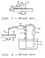
- Fig. 1 shows a Prior Art CMP apparatus.
- a polishing pad 20 is affixed to a circular polishing table 22 which rotates in a direction indicated by arrow 24 at a rate in the order of 1 to 100m RPM.
- a wafer carrier 26 is used to hold wafer 18 face down against the polishing pad 20. The wafer 18 is held in place by applying a vacuum to the backside of the wafer (not shown).
- the wafer carrier 26 also rotates as indicated by arrow 32, usually in the same direction as the polishing table 22, at a rate on the order of 1 to 100 RPM. Due to the rotation of the polishing table 22, the wafer 18 traverses a circular polishing path over the polishing pad 20.
- a force 28 is also applied in the downward or vertical direction against wafer 18 and presses the wafer 18 against the polishing pad 20 as it is being polished.
- the force 28 is typically in the order of 0 to 15 pounds per square inch and is applied by means of a shaft 30 that is attached to the back of wafer carrier 26. Slurry 21 is deposited on top of the polishing pad 20.
- Fig. 2 shows a typical Prior Art slurry delivery system.
- Slurry 21 of uniform chemical and mechanical composition is contained in the slurry vat 34 from where the slurry 21 is pumped by the diaphragm pump 36 in direction 38.
- the peristaltic pump 40 deposits controlled and intermittent amounts of slurry 21 onto the polishing pad 20 while the balance 44 of the slurry that had been pumped by the diaphragm pump 36 is returned to the slurry vat 34.
- the rate at which the slurry 21 is provided by the two pumps 36 and 40 can be under control of conditions of operation and environment such as type of surface being polished, rate of rotation of either the wafer and/or the polishing table, etc.
- US-A-6 106 371 (NAGAHARA RONALD J ET AL) 22 August 2000 (2000-08-22) disdoses an end effector designed to facilitate conditioning a surface of a polishing pad used in CMP of a substrate.
- the end effector includes an inwardly recessing contact surface capable of attaching to a conditioning disk having a conditioning surface such that the conditioning surface conforms to a substantial portion of the polishing pad, which protudes outwardly under operation and thereby effectively conditions a substantial portion of the polishing pad.
- the present invention teaches an in-situ slurry distribution and concurrent pad conditioning process and apparatus.
- the novelty of the present invention is that the polishing pads are mounted on a cylindrical platform that consists of a pad/core arrangement, instead of the conventional flat platform on which the polishing pads are placed.
- the cylindrical pad has motion in the X-Y-Z directions; the cylindrical pad in addition has rotational motion.
- the novelty of the present design consists of as unique pad/core design with the polishing pads mounted on the surface of the core. Evenly spaced openings are provided within the pad/core assembly for the location of slurry ports.
- the center of the core is hollow, slurry is pumped through the center of the core and exits the core through the slurry ports to the polishing pads and the pad conditioners.
- the present invention in addition incorporates a new slurry delivery arrangement.
- the slurry which can consist of a combination of more than one type or composition of slurry, is pumped in the conventional manner (for instance using diaphragm pumps) and flows through an orifice-flow meter where the multi-component slurries are combined and pumped through a single tube mixing coil. The actual mixing of the different slurries occurs within the mixing coil.
- the mixed slurry flows through a rotating driver that rotates the pad/core combination.
- the slurry can be metered very accurately unlike the slurry flow of conventional applications where the peristaltic pump causes a great deal of irregularities in the flow of the slurry.
- the present invention allows for the complete elimination of the peristaltic pump.
- a pad conditioner disc used as part of the present invention.
- This disc is of the same shape as the pad/core assembly and fits snuggly around this assembly.
- the pad conditioner conditions the polishing pads at the same time that the polishing operation takes place.
- the friction between the pad conditioner and the pad/core assembly can be varied during and as part of the polishing process thus further adding a parameter of control for the polishing operation.
- the method used for increasing the friction or pressure between the pad conditioner and the pad/core assembly can be of a number of designs, for instance air-actuated cylinders can be used for this purpose. This allows for very accurate control of this application parameter.
- Fig. 3 there is shown an exploded view of the polishing apparatus of the present invention.
- Fig. 3a shows the positioning of the wafers 52 that are being polished within the wafer carrier 53.
- the diagram 51 at the center of this cross sectional view indicates that the wafer carrier 53 has freedom of motion in the X-Y-Z direction in addition to the rotating motion 57.
- the wafers 52 that are to be polished are, in the conventional manner, affixed to the wafer carrier 53, the wafer carrier 53 also rotates around its axis, the direction of rotation 57 is, within the scope of the present invention, not critical.
- Fig. 3b provides further details of the pad/core assembly 54.
- Mounted on the outside of the hollow core 56 and in parallel with this core is an arrangement of four polishing pads 58.
- the number of polishing pads provided in this manner is not limited to the number of four as shown in Fig. 3b, any number of pads can be used which best suits and satisfies the need of a particular application.
- Pad conditioner disk 60 Adjacent to the pad/core assembly 54 is presented one pad conditioner disk 60.
- the number of pad conditioner disks that can be used within the scope of this invention can vary and is determined by optimum results obtained for a particular application of the present invention.
- Air actuated cylinders 62 can be used to urge the pad/core assembly 54 toward the wafer carrier 53 (Fig. 3a). By increasing the pressure by which the pad/core assembly 60 is urged toward the wafer carrier 53, the process of polishing the wafers 52 can be controlled.
- the process of wafer polishing is as follows: the pad/core assembly 54 rotates around its axis 82 stimulated by the rotary actuator 64.
- the diagram 86 within adjacent to the cross sectional view indicates that the pad/core assembly 54 has freedom of motion in the X-Y-Z direction in addition to the rotating motion.
- the direction of rotation of the pad/core assembly 54 is, within the scope of the present invention, not critical.
- the pad/core assembly 54 is mounted above and in close physical proximity to the wafers 52 affixed to the wafer carrier 53 such that the polishing pads 58 are in physical contact with the wafers 52 thus allowing the polishing pads 58 to polish the wafers 52.
- polishing pad conditioner 60 is or can be brought into physical contact with the rotating polishing pads 58. This latter contact between the polishing pads 58 and the polishing pad conditioner disc 60 refreshes or conditions the polishing pads 58.
- polishing pad conditioners 60 that is mounted on the pad/core arrangement 54 may vary and is dictated by requirements of particular applications. It is clear from the above that a large part of the outside surface of core 56 can be covered with pad conditioners 60, care must be taken that the pad conditioners 60 do not physically interfere with the top surface of the wafer carrier 53.
- the rotary driver 64 rotates that pad/core assembly 54 around its central axis 82.
- the rotary driver 64 can be of any conventional design; the design of the rotary driver 64 is not part of the present invention.
- Pumped through the rotary driver is the slurry 80 after it exits the slurry-mixing coil 66.
- the slurry is forced into the slurry-mixing coil from the slurry junction box 68.
- the slurry enters this box 68 from one or more sources of slurry, the rate at which this slurry from the various sources enters the junction vessel 68 is controlled at the entry points into the vessel by means of preset and adjustable openings 84 into the vessel 68.
- Fig. 3b Shown in Fig. 3b are two diaphragm pumps 72 that pump the slurry in direction 70, that is towards and into the slurry junction vessel 68.
- the slurry used for the polishing process is contained in the two slurry supply containers 74 and 76 which contain respectively slurry component 1 and slurry component 2.
- At the center of core 56 are provided channels or hollow zones 78 that run in the same direction as the axis 82 of the pad/core assemblage 54. These channels 78 are further connected to slurry ports (not shown in Fig. 3b) through which the slurry 80 is deposited and distributed to the polishing pads 58.
- Fig. 4a shows a cross sectional view of the pad/core combination 54 with a set of four polishing pads 58, the core 56 and the slurry ports 89.
- Fig. 4b shows a cross sectional view of the pad/core combination.
- the cross sectional view shows that the center 82 of the core 56 is hollow.
- the slurry ports 89 are also indicated.
- the flow of the slurry is as follows: the slurry is forced into the hollow zones or channels 78 provided for this purpose in the core 56 by the rotary driver 64 and exits these channels 78 via the slurry ports 89.
- the core is mounted on the core shaft or axis 82, which in turn is connected to the rotary driver 64.
- Fig. 5 shows the exploded view of the pad conditioner disc.
- the inside 88 of the conditioner disk is seeded with diamond in order to improve the effectiveness of the polishing pad renewal process.
- the conditioner disk itself (86) can be made using stainless steel or any other appropriate material.
Landscapes
- Engineering & Computer Science (AREA)
- Mechanical Engineering (AREA)
- Mechanical Treatment Of Semiconductor (AREA)
- Finish Polishing, Edge Sharpening, And Grinding By Specific Grinding Devices (AREA)
- Polishing Bodies And Polishing Tools (AREA)
- Grinding-Machine Dressing And Accessory Apparatuses (AREA)
Claims (29)
- Appareil pour une planarisation mécanique chimique de plaquettes de semi-conducteurs (52) comprenant :une plateforme (53) destinée à monter des plaquettes de semi-conducteurs (52) ;un moyen destiné à faire tourner ladite plateforme (53) pour monter des plaquettes de semi-conducteurs ;une plateforme cylindrique (54) destinée à monter des tampons à polir des semi-conducteurs (58) ;un moyen (64) destiné à faire tourner ladite plateforme cylindrique ;une disposition de tampons à polir cylindriques (56, 58) ;une disposition de conditionneur de tampons à polir (60) ;un moyen (64) destiné à faire tourner ledit tampon à polir cylindrique ;un moyen (62) destiné à faire varier la pression par laquelle les tampons à polir sont poussés vers les plaquettes de semi-conducteurs ;un moyen destiné à faire varier la pression par laquelle les disques conditionneurs de tampons sont poussés vers les tampons à polir ; etun moyen destiné à distribuer de manière égale de la pâte à l'intérieur de ladite plateforme cylindrique,caractérisé en ce que ledit moyen destiné à distribuer de manière égale la pâte à l'intérieur de ladite plateforme cylindrique comprend :(i) des moyens destinés à mélanger des pâtes multiples composés d'un serpentin mélangeur de pâte (66) à travers lequel des composants de pâte sont avancés, créant un flux de pâte ;(ii) des moyens (84) destinés à réguler la vitesse dudit flux de pâte en réglant les paramètres de régulation du flux de pâte ou des orifices montés à l'intérieur dudit flux de pâte ; et(iii) des moyens (72) destinés à faire entrer une multiplicité de pâtes composés d'une multiplicité de cuves de pâte ou conteneurs contenant lesdits composants de pâte, à partir desquels lesdits composants de pâte sont avancés par l'intermédiaire d'orifices préréglés dans ledit serpentin mélangeur de pâte, à partir desquels ladite pâte mélangée est poussée vers des canaux à l'intérieur de ladite plateforme cylindrique.
- Appareil selon la revendication 1, dans lequel ladite plateforme (53) destinée à monter lesdites plaquettes de semi-conducteurs (52) comprend une surface d'un porte-plaquettes.
- Appareil selon la revendication 1, dans lequel lesdits moyens destinés à faire tourner ledit porte-plaquettes comprennent un moteur d'entraînement rotatif.
- Appareil selon la revendication 1, dans lequel ladite plateforme cylindrique (54) destinée à monter les tampons à polir de semi-conducteurs (58) est composée d'un cylindre monté sur un axe ou arbre de cylindre.
- Appareil selon la revendication 1, dans lequel lesdits moyens destinés à faire tourner ladite plateforme cylindrique ou lesdits moyens destinés à faire tourner ledit porte-plaquettes sont composés d'un moteur d'entraînement rotatif.
- Appareil selon la revendication 1, dans lequel ladite disposition cylindrique de tampons à polir (56, 58) est composée de tampons à polir (58) montés sur la surface extérieure de ladite plateforme cylindrique dans la direction de l'axe de ladite plateforme et est composée d'un ou de multiples tampons à polir alors que ledit (lesdits) tampon(s) à polir présente(nt) la même ou approximativement la même longueur que la longueur de ladite plateforme cylindrique.
- Appareil selon la revendication 1, dans lequel ladite disposition cylindrique de tampons à polir (56, 58) comprend des tampons à polir montés sur la surface extérieure de ladite plateforme cylindrique dans la direction de l'axe de ladite plateforme et est composée d'une multiplicité de tampons à polir alors que lesdits tampons à polir présentent la même ou approximativement la même longueur que la longueur de ladite plateforme cylindrique.
- Appareil selon la revendication 1, dans lequel ladite disposition cylindrique de tampons à polir comprend des tampons à polir montés sur la surface extérieure de ladite plateforme cylindrique dans la direction de l'axe de ladite plateforme et est composée d'une multiplicité de tampons à polir alors que lesdits tampons à polir présentent une longueur qui peut ou ne peut pas être uniforme mais qui est plus courte que la longueur de ladite plateforme cylindrique.
- Appareil selon la revendication 1, dans lequel ladite disposition cylindrique de tampons à polir est composée d'au moins un disque concave avec une surface intérieure qui correspond et a le même profil que la surface extérieure desdits tampons à polir et qui est monté sur l'extérieur de ladite disposition de tampons à polir.
- Appareil selon la revendication 8, dans lequel chacun desdits au moins un disque concave est composé d'une configuration cylindrique en acier inoxydable dans laquelle la surface intérieure de chaque configuration cylindrique est imprégnée de diamant.
- Appareil selon la revendication 9, ladite disposition de conditionneur de tampon comprend une multiplicité desdits disques concaves montés sur la surface extérieure de ladite disposition de tampon à polir.
- Appareil selon la revendication 1, dans lequel le moyen destiné à faire varier ladite pression par laquelle lesdits disques conditionneurs de tampon sont poussés vers lesdits tampons à polir cylindriques est composé de cylindres pneumatiques fixés aux extrémités desdits tampons à polir.
- Procédé de planarisation mécanique chimique de plaquettes de semi-conducteurs consistant à :fournir une plateforme (53) destinée à monter des plaquettes de semi-conducteurs ;fournir un moyen destiné à faire tourner ladite plate-forme destinée à monter les plaquettes de semi-conducteurs ;fournir une plateforme cylindrique (54) destinée à monter les tampons à polir de semi-conducteurs ;fournir un moyen (64) destiné à faire tourner ladite plateforme cylindrique ;fournir une disposition de tampons à polir cylindriques (56, 58) ;fournir une disposition de conditionneurs de tampons à polir (60) ;fournir un moyen (64) destiné à faire tourner ledit tampon à polir ;fournir un moyen (62) destiné à faire varier la pression par laquelle les tampons à polir cylindriques sont poussés vers les plaquettes de semi-conducteurs ;fournir un moyen destiné à faire varier la pression par laquelle les disques conditionneurs de tampons sont poussés vers les tampons à polir ;caractérisé en ce qu'il consiste à :fournir un moyen pour distribuer de manière égale de la pâte à l'intérieur de ladite plateforme cylindrique en fournissant un ensemble d'ouvertures ou canaux fournis à l'intérieur de ladite plateforme cylindrique combiné à des orifices de pâte qui correspondent et sont reliés auxdites ouvertures ou canaux et qui sortent vers et sont reliés à la surface extérieure de ladite plateforme cylindrique et à fournir en outre un moyen destiné à faire entrer ladite pâte dans ladite plateforme cylindrique au moyen d'une pompe rotative, ledit moyen destiné à distribuer de manière égale la pâte à l'intérieur de ladite plateforme cylindrique étant un composant d'un appareil pour ladite planarisation mécanique chimique, ledit moyen destiné à distribuer de manière égale la pâte à l'intérieur de ladite plateforme cylindrique consistant en outre à :(i) fournir des moyens destinés à mélanger des pâtes multiples composés d'un serpentin mélangeur de pâte (66) à travers lequel des composants de pâte sont avancés, créant un flux de pâte ;(ii) fournir des moyens (84) destinés à réguler la vitesse dudit flux de pâte en réglant les paramètres de régulation du flux de pâte ou des orifices montés à l'intérieur dudit flux de pâte ; et(iii) fournir des moyens (72) destinés à faire entrer une multiplicité de pâtes composés d'une multiplicité de cuves de pâte ou conteneurs contenant lesdits composants de pâte, à partir desquels lesdits composants de pâte sont avancés par l'intermédiaire d'orifices préréglés dans ledit serpentin mélangeur de pâte, à partir desquels ladite pâte mélangée est poussée vers des canaux à l'intérieur de ladite plateforme cylindrique ; etplanariser ladite plaquette de semi-conducteur par une planarisation mécanique chimique.
- Procédé selon la revendication 13, dans lequel ladite plateforme destinée à monter lesdites plaquettes de semi-conducteurs est composée d'une surface supérieure ou face d'un porte-plaquettes.
- Procédé selon la revendication 13, dans lequel lesdits moyens de rotation dudit porte-plaquettes est composé d'un moteur d'entraînement rotatif.
- Procédé selon la revendication 13, dans lequel ladite plateforme cylindrique destinée à monter les tampons à polir de semi-conducteurs est composée d'un cylindre monté sur un axe ou arbre de cylindre.
- Procédé selon la revendication 13, dans lequel lesdits moyens destinés à faire tourner ladite plateforme cylindrique sont composés d'un moteur d'entraînement rotatif.
- Procédé selon la revendication 13, dans lequel ladite disposition de tampons à polir cylindriques est composée de tampons à polir montés sur une surface extérieure de ladite plateforme cylindrique et dans une direction de l'axe de ladite plateforme cylindrique et est composée d'un tampon à polir alors que ledit tampon à polir présente la même longueur ou approximativement la même longueur que celle dudit cylindre.
- Procédé selon la revendication 13, dans lequel ladite disposition de tampons à polir cylindriques est composée de tampons à polir montés sur la surface extérieure de ladite plateforme cylindrique et dans une direction de l'axe de ladite plateforme cylindrique et est composée d'une multiplicité de tampons à polir alors que lesdits tampons à polir présentent une longueur qui peut ou ne peut être uniforme mais est plus courte que la longueur de ladite plateforme cylindrique.
- Procédé selon la revendication 13, dans lequel ladite disposition de tampons à polir cylindriques est composée de tampons à polir montés sur une surface extérieure de ladite plateforme cylindrique et dans une direction de l'axe de ladite plateforme cylindrique et est composée d'une multiplicité de tampons à polir alors que lesdits tampons à polir présentent la même longueur ou approximativement la même longueur que celle de ladite plateforme cylindrique.
- Procédé selon la revendication 13, dans lequel ladite disposition de tampons à polir cylindriques est composée de tampons à polir montés sur la surface extérieure de ladite plateforme cylindrique et dans une direction de l'axe de ladite plateforme cylindrique et est composée d'une multiplicité de tampons à polir alors que lesdits tampons à polir présentent une longueur qui peut ou ne peut être uniforme mais est plus courte que la longueur de ladite plateforme cylindrique.
- Procédé selon la revendication 13, dans lequel ladite disposition de conditionneurs de tampons à polir est composée d'un disque concave avec une surface intérieure qui correspond à et présente le même profil que la surface extérieure desdits tampons à polir et qui est montée sur l'extérieur de ladite disposition de tampons à polir.
- Procédé selon la revendication 22, dans lequel ladite disposition de conditionneurs de tampons à polir est composée d'une configuration cylindrique en acier inoxydable dans laquelle la surface intérieure de ladite configuration cylindrique est imprégnée de diamant.
- Procédé selon la revendication 22, dans lequel ladite disposition de conditionneurs de tampons à polir est composée d'une multiplicité desdits disques concaves montés sur l'extérieur de ladite disposition de tampons à polir.
- Procédé selon la revendication 13, dans lequel le moyen destiné à faire varier ladite pression par laquelle lesdits disques conditionneurs de tampon cylindriques sont poussés vers lesdits tampons à polir cylindriques est composé de cylindres pneumatiques fixés aux extrémités desdits tampons à polir.
- Procédé selon la revendication 13, dans lequel le procédé destiné à faire varier la pression par laquelle lesdits tampons à polir sont poussés vers lesdites plaquettes de semi-conducteurs est composé de cylindres pneumatiques fixés aux extrémités desdits tampons à polir.
- Appareil selon la revendication 1, dans lequel ledit moyen destiné à distribuer de manière égale la pâte est composé d'un système d'alimentation en pâte qui pompe la pâte dans des canaux creux à l'intérieur de la plateforme de tampons à polir à partir desquels la pâte est libérée vers la surface des tampons à polir au moyen d'orifices de pâte qui relient lesdits canaux à ladite surface de ladite plateforme destinée à monter lesdits tampons à polir.
- Appareil selon la revendication 27, comprenant en outre des moyens destinés à faire entrer la pâte dans ladite plateforme cylindrique, dans lequel lesdits moyens sont composés d'une pompe contenue à l'intérieur de l'activateur rotatif qui fait tourner ladite plateforme cylindrique.
- Appareil selon la revendication 1, dans lequel lesdits composants de pâte sont mélangés dans lesdits moyens destinés à mélanger des pâtes multiples au moyen d'une propulsion rotative.
Applications Claiming Priority (2)
| Application Number | Priority Date | Filing Date | Title |
|---|---|---|---|
| US09/195,654 US6235635B1 (en) | 1998-11-19 | 1998-11-19 | Linear CMP tool design using in-situ slurry distribution and concurrent pad conditioning |
| US195654 | 1998-11-19 |
Publications (3)
| Publication Number | Publication Date |
|---|---|
| EP1002626A2 EP1002626A2 (fr) | 2000-05-24 |
| EP1002626A3 EP1002626A3 (fr) | 2003-07-02 |
| EP1002626B1 true EP1002626B1 (fr) | 2007-01-03 |
Family
ID=22722214
Family Applications (1)
| Application Number | Title | Priority Date | Filing Date |
|---|---|---|---|
| EP99480059A Expired - Lifetime EP1002626B1 (fr) | 1998-11-19 | 1999-07-09 | Outil linéaire de polissage mécano-chimique avec distribution de in-situ de la suspension de polissage et dressage simultané du tampon de polissage |
Country Status (6)
| Country | Link |
|---|---|
| US (2) | US6235635B1 (fr) |
| EP (1) | EP1002626B1 (fr) |
| JP (1) | JP2000158324A (fr) |
| AT (1) | ATE350195T1 (fr) |
| DE (1) | DE69934658T2 (fr) |
| SG (1) | SG91812A1 (fr) |
Families Citing this family (18)
| Publication number | Priority date | Publication date | Assignee | Title |
|---|---|---|---|---|
| US6235635B1 (en) * | 1998-11-19 | 2001-05-22 | Chartered Semiconductor Manufacturing Ltd. | Linear CMP tool design using in-situ slurry distribution and concurrent pad conditioning |
| US6156659A (en) * | 1998-11-19 | 2000-12-05 | Chartered Semiconductor Manufacturing Ltd. | Linear CMP tool design with closed loop slurry distribution |
| US6514863B1 (en) * | 2000-02-25 | 2003-02-04 | Vitesse Semiconductor Corporation | Method and apparatus for slurry distribution profile control in chemical-mechanical planarization |
| US7086933B2 (en) * | 2002-04-22 | 2006-08-08 | Applied Materials, Inc. | Flexible polishing fluid delivery system |
| US6572731B1 (en) | 2002-01-18 | 2003-06-03 | Chartered Semiconductor Manufacturing Ltd. | Self-siphoning CMP tool design for applications such as copper CMP and low-k dielectric CMP |
| TW538853U (en) * | 2002-05-03 | 2003-06-21 | Nanya Technology Corp | Device for mixing polishing solvent with consistent property and slurry supply system |
| US20030236489A1 (en) | 2002-06-21 | 2003-12-25 | Baxter International, Inc. | Method and apparatus for closed-loop flow control system |
| US6875086B2 (en) * | 2003-01-10 | 2005-04-05 | Intel Corporation | Surface planarization |
| JP4447279B2 (ja) * | 2003-10-15 | 2010-04-07 | キヤノンアネルバ株式会社 | 成膜装置 |
| CN101817162A (zh) * | 2004-01-26 | 2010-09-01 | Tbw工业有限公司 | 用于化学机械平面化的多步骤、原位垫修整系统 |
| EP1846308B1 (fr) * | 2004-12-03 | 2009-03-11 | Dentsply International, Inc. | Conditionnement et systeme distributeur |
| US20070131562A1 (en) * | 2005-12-08 | 2007-06-14 | Applied Materials, Inc. | Method and apparatus for planarizing a substrate with low fluid consumption |
| US8152975B2 (en) * | 2007-03-30 | 2012-04-10 | Ascentool International | Deposition system with improved material utilization |
| US7828625B2 (en) * | 2007-10-30 | 2010-11-09 | United Microelectronics Corp. | Method of supplying polishing liquid |
| JP2009285774A (ja) * | 2008-05-29 | 2009-12-10 | Showa Denko Kk | 表面加工方法及び装置 |
| KR101164101B1 (ko) * | 2010-01-11 | 2012-07-12 | 주식회사 엘지실트론 | 롤러 구조를 이용한 양면 연마 장치 |
| US8535118B2 (en) * | 2011-09-20 | 2013-09-17 | International Business Machines Corporation | Multi-spindle chemical mechanical planarization tool |
| KR101587894B1 (ko) * | 2015-02-17 | 2016-01-25 | 주식회사 티에스시 | 슬러리공급장치 |
Family Cites Families (18)
| Publication number | Priority date | Publication date | Assignee | Title |
|---|---|---|---|---|
| JPH0766160A (ja) * | 1993-08-24 | 1995-03-10 | Sony Corp | 半導体基板の研磨方法及び研磨装置 |
| US5650039A (en) | 1994-03-02 | 1997-07-22 | Applied Materials, Inc. | Chemical mechanical polishing apparatus with improved slurry distribution |
| JP2647050B2 (ja) * | 1995-03-31 | 1997-08-27 | 日本電気株式会社 | ウェハ研磨装置 |
| US5775983A (en) | 1995-05-01 | 1998-07-07 | Applied Materials, Inc. | Apparatus and method for conditioning a chemical mechanical polishing pad |
| US5665656A (en) | 1995-05-17 | 1997-09-09 | National Semiconductor Corporation | Method and apparatus for polishing a semiconductor substrate wafer |
| US5827115A (en) * | 1995-07-19 | 1998-10-27 | Ebara Corporation | Polishing apparatus |
| KR100189970B1 (ko) * | 1995-08-07 | 1999-06-01 | 윤종용 | 웨이퍼 연마장치 |
| US5785585A (en) | 1995-09-18 | 1998-07-28 | International Business Machines Corporation | Polish pad conditioner with radial compensation |
| US5709593A (en) | 1995-10-27 | 1998-01-20 | Applied Materials, Inc. | Apparatus and method for distribution of slurry in a chemical mechanical polishing system |
| US5804507A (en) * | 1995-10-27 | 1998-09-08 | Applied Materials, Inc. | Radially oscillating carousel processing system for chemical mechanical polishing |
| US5792709A (en) | 1995-12-19 | 1998-08-11 | Micron Technology, Inc. | High-speed planarizing apparatus and method for chemical mechanical planarization of semiconductor wafers |
| KR100202659B1 (ko) * | 1996-07-09 | 1999-06-15 | 구본준 | 반도체웨이퍼의 기계화학적 연마장치 |
| US5664990A (en) * | 1996-07-29 | 1997-09-09 | Integrated Process Equipment Corp. | Slurry recycling in CMP apparatus |
| US5782675A (en) | 1996-10-21 | 1998-07-21 | Micron Technology, Inc. | Apparatus and method for refurbishing fixed-abrasive polishing pads used in chemical-mechanical planarization of semiconductor wafers |
| US5811355A (en) * | 1996-10-31 | 1998-09-22 | Aiwa Co., Ltd. | Enhanced chemical-mechanical polishing (E-CMP) method of forming a planar surface on a thin film magnetic head to avoid pole recession |
| US5967881A (en) * | 1997-05-29 | 1999-10-19 | Tucker; Thomas N. | Chemical mechanical planarization tool having a linear polishing roller |
| US6106371A (en) * | 1997-10-30 | 2000-08-22 | Lsi Logic Corporation | Effective pad conditioning |
| US6235635B1 (en) * | 1998-11-19 | 2001-05-22 | Chartered Semiconductor Manufacturing Ltd. | Linear CMP tool design using in-situ slurry distribution and concurrent pad conditioning |
-
1998
- 1998-11-19 US US09/195,654 patent/US6235635B1/en not_active Expired - Fee Related
-
1999
- 1999-03-31 SG SG9901618A patent/SG91812A1/en unknown
- 1999-07-09 DE DE69934658T patent/DE69934658T2/de not_active Expired - Fee Related
- 1999-07-09 EP EP99480059A patent/EP1002626B1/fr not_active Expired - Lifetime
- 1999-07-09 AT AT99480059T patent/ATE350195T1/de not_active IP Right Cessation
- 1999-11-18 JP JP32865099A patent/JP2000158324A/ja active Pending
-
2000
- 2000-11-22 US US09/718,466 patent/US6547652B1/en not_active Expired - Lifetime
Also Published As
| Publication number | Publication date |
|---|---|
| ATE350195T1 (de) | 2007-01-15 |
| EP1002626A2 (fr) | 2000-05-24 |
| SG91812A1 (en) | 2002-10-15 |
| JP2000158324A (ja) | 2000-06-13 |
| EP1002626A3 (fr) | 2003-07-02 |
| US6547652B1 (en) | 2003-04-15 |
| DE69934658D1 (de) | 2007-02-15 |
| US6235635B1 (en) | 2001-05-22 |
| DE69934658T2 (de) | 2007-11-15 |
Similar Documents
| Publication | Publication Date | Title |
|---|---|---|
| US6235635B1 (en) | Linear CMP tool design using in-situ slurry distribution and concurrent pad conditioning | |
| US6264789B1 (en) | System for dispensing polishing liquid during chemical mechanical polishing of a semiconductor wafer | |
| EP1250215B1 (fr) | Appareil et technique permettant de maitriser le polissage et la planarisation de tranches de semi-conducteur | |
| US6409580B1 (en) | Rigid polishing pad conditioner for chemical mechanical polishing tool | |
| US7104875B2 (en) | Chemical mechanical polishing apparatus with rotating belt | |
| CN201239910Y (zh) | 一种抛光垫调节器及具有抛光垫调节器的化学机械装置 | |
| US6390903B1 (en) | Precise polishing apparatus and method | |
| US7997958B2 (en) | Apparatuses and methods for conditioning polishing pads used in polishing micro-device workpieces | |
| US20040203325A1 (en) | Conditioner disk for use in chemical mechanical polishing | |
| US6241583B1 (en) | Chemical mechanical polishing with a plurality of polishing sheets | |
| US10807213B2 (en) | Chemical mechanical polishing apparatus and method | |
| JP2000349056A (ja) | 固定研磨部材のコンディショニング | |
| US6572445B2 (en) | Multizone slurry delivery for chemical mechanical polishing tool | |
| US6156659A (en) | Linear CMP tool design with closed loop slurry distribution | |
| KR100773190B1 (ko) | 가동 연마 시트를 이용한 화학 기계 연마 장치 및 방법 | |
| US6439978B1 (en) | Substrate polishing system using roll-to-roll fixed abrasive | |
| US7229343B2 (en) | Orbiting indexable belt polishing station for chemical mechanical polishing | |
| CN110653717B (zh) | 化学机械平坦化系统和方法以及研磨晶圆的方法 | |
| JP2002187062A (ja) | 平面研磨装置、平面研磨方法及びそれに使用される砥石 | |
| US6572731B1 (en) | Self-siphoning CMP tool design for applications such as copper CMP and low-k dielectric CMP | |
| US20020072307A1 (en) | Apparatus and method for chemical mechanical planarization using a fixed-abrasive polishing pad | |
| US6752698B1 (en) | Method and apparatus for conditioning fixed-abrasive polishing pads | |
| US7175515B2 (en) | Static pad conditioner | |
| US6832948B1 (en) | Thermal preconditioning fixed abrasive articles | |
| TW449532B (en) | A novel linear CMP tool design using in-situ slurry distribution and concurrent pad conditioning |
Legal Events
| Date | Code | Title | Description |
|---|---|---|---|
| PUAI | Public reference made under article 153(3) epc to a published international application that has entered the european phase |
Free format text: ORIGINAL CODE: 0009012 |
|
| AK | Designated contracting states |
Kind code of ref document: A2 Designated state(s): AT BE CH CY DE DK ES FI FR GB GR IE IT LI LU MC NL PT SE |
|
| AX | Request for extension of the european patent |
Free format text: AL;LT;LV;MK;RO;SI |
|
| RIC1 | Information provided on ipc code assigned before grant |
Ipc: 7H 01L 21/304 - Ipc: 7B 24B 53/007 B Ipc: 7B 24D 13/12 B Ipc: 7B 24B 57/02 B Ipc: 7B 24B 37/04 A |
|
| PUAL | Search report despatched |
Free format text: ORIGINAL CODE: 0009013 |
|
| AK | Designated contracting states |
Designated state(s): AT BE CH CY DE DK ES FI FR GB GR IE IT LI LU MC NL PT SE |
|
| AX | Request for extension of the european patent |
Extension state: AL LT LV MK RO SI |
|
| 17P | Request for examination filed |
Effective date: 20040102 |
|
| AKX | Designation fees paid |
Designated state(s): AT BE CH CY DE DK ES FI FR GB GR IE IT LI LU MC NL PT SE |
|
| 17Q | First examination report despatched |
Effective date: 20040826 |
|
| APBN | Date of receipt of notice of appeal recorded |
Free format text: ORIGINAL CODE: EPIDOSNNOA2E |
|
| APBR | Date of receipt of statement of grounds of appeal recorded |
Free format text: ORIGINAL CODE: EPIDOSNNOA3E |
|
| APBV | Interlocutory revision of appeal recorded |
Free format text: ORIGINAL CODE: EPIDOSNIRAPE |
|
| GRAP | Despatch of communication of intention to grant a patent |
Free format text: ORIGINAL CODE: EPIDOSNIGR1 |
|
| GRAS | Grant fee paid |
Free format text: ORIGINAL CODE: EPIDOSNIGR3 |
|
| GRAA | (expected) grant |
Free format text: ORIGINAL CODE: 0009210 |
|
| AK | Designated contracting states |
Kind code of ref document: B1 Designated state(s): AT BE CH CY DE DK ES FI FR GB GR IE IT LI LU MC NL PT SE |
|
| PG25 | Lapsed in a contracting state [announced via postgrant information from national office to epo] |
Ref country code: NL Free format text: LAPSE BECAUSE OF FAILURE TO SUBMIT A TRANSLATION OF THE DESCRIPTION OR TO PAY THE FEE WITHIN THE PRESCRIBED TIME-LIMIT Effective date: 20070103 Ref country code: LI Free format text: LAPSE BECAUSE OF FAILURE TO SUBMIT A TRANSLATION OF THE DESCRIPTION OR TO PAY THE FEE WITHIN THE PRESCRIBED TIME-LIMIT Effective date: 20070103 Ref country code: FI Free format text: LAPSE BECAUSE OF FAILURE TO SUBMIT A TRANSLATION OF THE DESCRIPTION OR TO PAY THE FEE WITHIN THE PRESCRIBED TIME-LIMIT Effective date: 20070103 Ref country code: DK Free format text: LAPSE BECAUSE OF FAILURE TO SUBMIT A TRANSLATION OF THE DESCRIPTION OR TO PAY THE FEE WITHIN THE PRESCRIBED TIME-LIMIT Effective date: 20070103 Ref country code: CH Free format text: LAPSE BECAUSE OF FAILURE TO SUBMIT A TRANSLATION OF THE DESCRIPTION OR TO PAY THE FEE WITHIN THE PRESCRIBED TIME-LIMIT Effective date: 20070103 Ref country code: AT Free format text: LAPSE BECAUSE OF FAILURE TO SUBMIT A TRANSLATION OF THE DESCRIPTION OR TO PAY THE FEE WITHIN THE PRESCRIBED TIME-LIMIT Effective date: 20070103 |
|
| REG | Reference to a national code |
Ref country code: GB Ref legal event code: FG4D |
|
| REF | Corresponds to: |
Ref document number: 69934658 Country of ref document: DE Date of ref document: 20070215 Kind code of ref document: P |
|
| PG25 | Lapsed in a contracting state [announced via postgrant information from national office to epo] |
Ref country code: SE Free format text: LAPSE BECAUSE OF FAILURE TO SUBMIT A TRANSLATION OF THE DESCRIPTION OR TO PAY THE FEE WITHIN THE PRESCRIBED TIME-LIMIT Effective date: 20070403 |
|
| PG25 | Lapsed in a contracting state [announced via postgrant information from national office to epo] |
Ref country code: ES Free format text: LAPSE BECAUSE OF FAILURE TO SUBMIT A TRANSLATION OF THE DESCRIPTION OR TO PAY THE FEE WITHIN THE PRESCRIBED TIME-LIMIT Effective date: 20070414 |
|
| PG25 | Lapsed in a contracting state [announced via postgrant information from national office to epo] |
Ref country code: PT Free format text: LAPSE BECAUSE OF FAILURE TO SUBMIT A TRANSLATION OF THE DESCRIPTION OR TO PAY THE FEE WITHIN THE PRESCRIBED TIME-LIMIT Effective date: 20070604 |
|
| ET | Fr: translation filed | ||
| NLV1 | Nl: lapsed or annulled due to failure to fulfill the requirements of art. 29p and 29m of the patents act | ||
| REG | Reference to a national code |
Ref country code: CH Ref legal event code: PL |
|
| PLBE | No opposition filed within time limit |
Free format text: ORIGINAL CODE: 0009261 |
|
| STAA | Information on the status of an ep patent application or granted ep patent |
Free format text: STATUS: NO OPPOSITION FILED WITHIN TIME LIMIT |
|
| 26N | No opposition filed |
Effective date: 20071005 |
|
| PG25 | Lapsed in a contracting state [announced via postgrant information from national office to epo] |
Ref country code: BE Free format text: LAPSE BECAUSE OF FAILURE TO SUBMIT A TRANSLATION OF THE DESCRIPTION OR TO PAY THE FEE WITHIN THE PRESCRIBED TIME-LIMIT Effective date: 20070103 |
|
| GBPC | Gb: european patent ceased through non-payment of renewal fee |
Effective date: 20070709 |
|
| PG25 | Lapsed in a contracting state [announced via postgrant information from national office to epo] |
Ref country code: MC Free format text: LAPSE BECAUSE OF NON-PAYMENT OF DUE FEES Effective date: 20070731 Ref country code: GR Free format text: LAPSE BECAUSE OF FAILURE TO SUBMIT A TRANSLATION OF THE DESCRIPTION OR TO PAY THE FEE WITHIN THE PRESCRIBED TIME-LIMIT Effective date: 20070404 |
|
| PG25 | Lapsed in a contracting state [announced via postgrant information from national office to epo] |
Ref country code: GB Free format text: LAPSE BECAUSE OF NON-PAYMENT OF DUE FEES Effective date: 20070709 |
|
| PG25 | Lapsed in a contracting state [announced via postgrant information from national office to epo] |
Ref country code: IE Free format text: LAPSE BECAUSE OF NON-PAYMENT OF DUE FEES Effective date: 20070709 |
|
| PGFP | Annual fee paid to national office [announced via postgrant information from national office to epo] |
Ref country code: DE Payment date: 20080724 Year of fee payment: 10 |
|
| PGFP | Annual fee paid to national office [announced via postgrant information from national office to epo] |
Ref country code: IT Payment date: 20080731 Year of fee payment: 10 Ref country code: FR Payment date: 20080804 Year of fee payment: 10 |
|
| PG25 | Lapsed in a contracting state [announced via postgrant information from national office to epo] |
Ref country code: CY Free format text: LAPSE BECAUSE OF FAILURE TO SUBMIT A TRANSLATION OF THE DESCRIPTION OR TO PAY THE FEE WITHIN THE PRESCRIBED TIME-LIMIT Effective date: 20070103 |
|
| PG25 | Lapsed in a contracting state [announced via postgrant information from national office to epo] |
Ref country code: LU Free format text: LAPSE BECAUSE OF NON-PAYMENT OF DUE FEES Effective date: 20070709 |
|
| REG | Reference to a national code |
Ref country code: FR Ref legal event code: ST Effective date: 20100331 |
|
| PG25 | Lapsed in a contracting state [announced via postgrant information from national office to epo] |
Ref country code: FR Free format text: LAPSE BECAUSE OF NON-PAYMENT OF DUE FEES Effective date: 20090731 |
|
| PG25 | Lapsed in a contracting state [announced via postgrant information from national office to epo] |
Ref country code: DE Free format text: LAPSE BECAUSE OF NON-PAYMENT OF DUE FEES Effective date: 20100202 |
|
| PG25 | Lapsed in a contracting state [announced via postgrant information from national office to epo] |
Ref country code: IT Free format text: LAPSE BECAUSE OF NON-PAYMENT OF DUE FEES Effective date: 20090709 |