EP1002949A2 - Eolienne à axe vertical - Google Patents
Eolienne à axe vertical Download PDFInfo
- Publication number
- EP1002949A2 EP1002949A2 EP99118279A EP99118279A EP1002949A2 EP 1002949 A2 EP1002949 A2 EP 1002949A2 EP 99118279 A EP99118279 A EP 99118279A EP 99118279 A EP99118279 A EP 99118279A EP 1002949 A2 EP1002949 A2 EP 1002949A2
- Authority
- EP
- European Patent Office
- Prior art keywords
- rotor
- power plant
- wind power
- wind
- bearing
- Prior art date
- Legal status (The legal status is an assumption and is not a legal conclusion. Google has not performed a legal analysis and makes no representation as to the accuracy of the status listed.)
- Withdrawn
Links
- 230000005540 biological transmission Effects 0.000 claims description 11
- 238000005253 cladding Methods 0.000 claims description 8
- 230000000694 effects Effects 0.000 claims description 3
- 239000007788 liquid Substances 0.000 claims description 3
- 230000001681 protective effect Effects 0.000 claims description 2
- 239000002131 composite material Substances 0.000 claims 1
- 229910052751 metal Inorganic materials 0.000 claims 1
- 239000002184 metal Substances 0.000 claims 1
- 150000002739 metals Chemical class 0.000 claims 1
- 229920003023 plastic Polymers 0.000 claims 1
- 239000004033 plastic Substances 0.000 claims 1
- 230000014616 translation Effects 0.000 claims 1
- 238000013519 translation Methods 0.000 claims 1
- 238000009420 retrofitting Methods 0.000 description 2
- 230000003068 static effect Effects 0.000 description 2
- 208000012886 Vertigo Diseases 0.000 description 1
- 230000015572 biosynthetic process Effects 0.000 description 1
- 230000005611 electricity Effects 0.000 description 1
- 230000003993 interaction Effects 0.000 description 1
- 230000011218 segmentation Effects 0.000 description 1
- 230000007306 turnover Effects 0.000 description 1
Images


Classifications
-
- F—MECHANICAL ENGINEERING; LIGHTING; HEATING; WEAPONS; BLASTING
- F03—MACHINES OR ENGINES FOR LIQUIDS; WIND, SPRING, OR WEIGHT MOTORS; PRODUCING MECHANICAL POWER OR A REACTIVE PROPULSIVE THRUST, NOT OTHERWISE PROVIDED FOR
- F03D—WIND MOTORS
- F03D1/00—Wind motors with rotation axis substantially parallel to the air flow entering the rotor
- F03D1/02—Wind motors with rotation axis substantially parallel to the air flow entering the rotor having a plurality of rotors
-
- F—MECHANICAL ENGINEERING; LIGHTING; HEATING; WEAPONS; BLASTING
- F03—MACHINES OR ENGINES FOR LIQUIDS; WIND, SPRING, OR WEIGHT MOTORS; PRODUCING MECHANICAL POWER OR A REACTIVE PROPULSIVE THRUST, NOT OTHERWISE PROVIDED FOR
- F03D—WIND MOTORS
- F03D15/00—Transmission of mechanical power
- F03D15/10—Transmission of mechanical power using gearing not limited to rotary motion, e.g. with oscillating or reciprocating members
-
- F—MECHANICAL ENGINEERING; LIGHTING; HEATING; WEAPONS; BLASTING
- F03—MACHINES OR ENGINES FOR LIQUIDS; WIND, SPRING, OR WEIGHT MOTORS; PRODUCING MECHANICAL POWER OR A REACTIVE PROPULSIVE THRUST, NOT OTHERWISE PROVIDED FOR
- F03D—WIND MOTORS
- F03D3/00—Wind motors with rotation axis substantially perpendicular to the air flow entering the rotor
- F03D3/02—Wind motors with rotation axis substantially perpendicular to the air flow entering the rotor having a plurality of rotors
-
- F—MECHANICAL ENGINEERING; LIGHTING; HEATING; WEAPONS; BLASTING
- F03—MACHINES OR ENGINES FOR LIQUIDS; WIND, SPRING, OR WEIGHT MOTORS; PRODUCING MECHANICAL POWER OR A REACTIVE PROPULSIVE THRUST, NOT OTHERWISE PROVIDED FOR
- F03D—WIND MOTORS
- F03D3/00—Wind motors with rotation axis substantially perpendicular to the air flow entering the rotor
- F03D3/04—Wind motors with rotation axis substantially perpendicular to the air flow entering the rotor having stationary wind-guiding means, e.g. with shrouds or channels
- F03D3/0436—Wind motors with rotation axis substantially perpendicular to the air flow entering the rotor having stationary wind-guiding means, e.g. with shrouds or channels for shielding one side of the rotor
- F03D3/0472—Wind motors with rotation axis substantially perpendicular to the air flow entering the rotor having stationary wind-guiding means, e.g. with shrouds or channels for shielding one side of the rotor the shield orientation being adaptable to the wind motor
- F03D3/049—Wind motors with rotation axis substantially perpendicular to the air flow entering the rotor having stationary wind-guiding means, e.g. with shrouds or channels for shielding one side of the rotor the shield orientation being adaptable to the wind motor with converging inlets, i.e. the shield intercepting an area greater than the effective rotor area
-
- F—MECHANICAL ENGINEERING; LIGHTING; HEATING; WEAPONS; BLASTING
- F03—MACHINES OR ENGINES FOR LIQUIDS; WIND, SPRING, OR WEIGHT MOTORS; PRODUCING MECHANICAL POWER OR A REACTIVE PROPULSIVE THRUST, NOT OTHERWISE PROVIDED FOR
- F03D—WIND MOTORS
- F03D80/00—Details, components or accessories not provided for in groups F03D1/00 - F03D17/00
- F03D80/70—Bearing or lubricating arrangements
-
- F—MECHANICAL ENGINEERING; LIGHTING; HEATING; WEAPONS; BLASTING
- F03—MACHINES OR ENGINES FOR LIQUIDS; WIND, SPRING, OR WEIGHT MOTORS; PRODUCING MECHANICAL POWER OR A REACTIVE PROPULSIVE THRUST, NOT OTHERWISE PROVIDED FOR
- F03D—WIND MOTORS
- F03D9/00—Adaptations of wind motors for special use; Combinations of wind motors with apparatus driven thereby; Wind motors specially adapted for installation in particular locations
- F03D9/20—Wind motors characterised by the driven apparatus
- F03D9/25—Wind motors characterised by the driven apparatus the apparatus being an electrical generator
-
- F—MECHANICAL ENGINEERING; LIGHTING; HEATING; WEAPONS; BLASTING
- F05—INDEXING SCHEMES RELATING TO ENGINES OR PUMPS IN VARIOUS SUBCLASSES OF CLASSES F01-F04
- F05B—INDEXING SCHEME RELATING TO WIND, SPRING, WEIGHT, INERTIA OR LIKE MOTORS, TO MACHINES OR ENGINES FOR LIQUIDS COVERED BY SUBCLASSES F03B, F03D AND F03G
- F05B2240/00—Components
- F05B2240/90—Mounting on supporting structures or systems
- F05B2240/91—Mounting on supporting structures or systems on a stationary structure
- F05B2240/911—Mounting on supporting structures or systems on a stationary structure already existing for a prior purpose
-
- Y—GENERAL TAGGING OF NEW TECHNOLOGICAL DEVELOPMENTS; GENERAL TAGGING OF CROSS-SECTIONAL TECHNOLOGIES SPANNING OVER SEVERAL SECTIONS OF THE IPC; TECHNICAL SUBJECTS COVERED BY FORMER USPC CROSS-REFERENCE ART COLLECTIONS [XRACs] AND DIGESTS
- Y02—TECHNOLOGIES OR APPLICATIONS FOR MITIGATION OR ADAPTATION AGAINST CLIMATE CHANGE
- Y02E—REDUCTION OF GREENHOUSE GAS [GHG] EMISSIONS, RELATED TO ENERGY GENERATION, TRANSMISSION OR DISTRIBUTION
- Y02E10/00—Energy generation through renewable energy sources
- Y02E10/70—Wind energy
- Y02E10/72—Wind turbines with rotation axis in wind direction
-
- Y—GENERAL TAGGING OF NEW TECHNOLOGICAL DEVELOPMENTS; GENERAL TAGGING OF CROSS-SECTIONAL TECHNOLOGIES SPANNING OVER SEVERAL SECTIONS OF THE IPC; TECHNICAL SUBJECTS COVERED BY FORMER USPC CROSS-REFERENCE ART COLLECTIONS [XRACs] AND DIGESTS
- Y02—TECHNOLOGIES OR APPLICATIONS FOR MITIGATION OR ADAPTATION AGAINST CLIMATE CHANGE
- Y02E—REDUCTION OF GREENHOUSE GAS [GHG] EMISSIONS, RELATED TO ENERGY GENERATION, TRANSMISSION OR DISTRIBUTION
- Y02E10/00—Energy generation through renewable energy sources
- Y02E10/70—Wind energy
- Y02E10/728—Onshore wind turbines
-
- Y—GENERAL TAGGING OF NEW TECHNOLOGICAL DEVELOPMENTS; GENERAL TAGGING OF CROSS-SECTIONAL TECHNOLOGIES SPANNING OVER SEVERAL SECTIONS OF THE IPC; TECHNICAL SUBJECTS COVERED BY FORMER USPC CROSS-REFERENCE ART COLLECTIONS [XRACs] AND DIGESTS
- Y02—TECHNOLOGIES OR APPLICATIONS FOR MITIGATION OR ADAPTATION AGAINST CLIMATE CHANGE
- Y02E—REDUCTION OF GREENHOUSE GAS [GHG] EMISSIONS, RELATED TO ENERGY GENERATION, TRANSMISSION OR DISTRIBUTION
- Y02E10/00—Energy generation through renewable energy sources
- Y02E10/70—Wind energy
- Y02E10/74—Wind turbines with rotation axis perpendicular to the wind direction
-
- Y—GENERAL TAGGING OF NEW TECHNOLOGICAL DEVELOPMENTS; GENERAL TAGGING OF CROSS-SECTIONAL TECHNOLOGIES SPANNING OVER SEVERAL SECTIONS OF THE IPC; TECHNICAL SUBJECTS COVERED BY FORMER USPC CROSS-REFERENCE ART COLLECTIONS [XRACs] AND DIGESTS
- Y10—TECHNICAL SUBJECTS COVERED BY FORMER USPC
- Y10S—TECHNICAL SUBJECTS COVERED BY FORMER USPC CROSS-REFERENCE ART COLLECTIONS [XRACs] AND DIGESTS
- Y10S415/00—Rotary kinetic fluid motors or pumps
- Y10S415/905—Natural fluid current motor
- Y10S415/908—Axial flow runner
Definitions
- the invention relates to a wind turbine with a horizontal rotating rotor, as well as a rotor for this horizontally rotating wind turbine that a variety of rotor blades and connected to a generator is.
- GB 20414587 A describes a vertical axis known rotating wind turbine, the areas of a housing is surrounded.
- the housing is shaped by a wind vane Aligned in the wind so that the opposing wind Rotor blades are protected.
- a wind power plant is known from DD 296 734 rotates about a vertical axis, the impeller by a Protective shield in the shape of a segment of a circle, which surrounds itself the axis of the impeller rotates.
- DE 38 29 112 describes a wind turbine with a Known rotor blades equipped with a generator connected, and which is encapsulated by a housing that can be freely aligned in the desired wind direction.
- the housing has a funnel-shaped inlet, which is provided with air baffles. Through an air outlet, the smaller is designed to accelerate the air.
- the inflow funnel is aligned against the wind.
- a wheel-shaped wind turbine is known from DE 196 48 632, whose rotor has a plurality of trough-shaped rotor blades has, the wind turbine surrounded by a housing is constructed like the housing of the wind turbine, the is known from the publication DE 38 29 112.
- the object of the present invention is a wind turbine to provide, which has a high efficiency and which is easy to install and with existing ones Wind turbines can be combined. It should also be possible be to expand the system as needed without major to meet technical and financial expenses. Another The task is to simply attach the device on existing towers. Another task is the unpleasant shadow formation of the conventional To avoid wind turbines. There is still another task in, for this device one yourself in the horizontal provide rotating rotor, the optimal aerodynamic Has properties around the air resistance of the flowing back To minimize air.
- the rotor blades are completely surrounded by a fairing, the cover having an air inlet and an air outlet has, and the cladding depending on the wind direction Alignment means is aligned so that the air intake is optimal is directed against the wind direction.
- the cladding is rotatably supported and is supported by a wind vane-shaped fairing aligner aligned.
- the paneling is made by aligned a servomotor that is controlled by a wind sensor becomes.
- the wind turbine has means for subsequent attachment on existing masts.
- This wind turbine consists of a rotating in the horizontal direction annular rotor which has a plurality of rotor blades.
- the wind turbine also includes an annular one Bearing ring on which the rotor rotates on bearings, whereby the bearing ring extends around the mast and the bearings through Connection struts are attached to the mast.
- a reversal this principle is also conceivable, so that the bearing ring is static and the rotor is connected to bearings that are on the Run the bearing ring.
- the connecting struts are designed so that they are different strong masts can be attached variable without making significant design changes have to.
- the rotor is connected to a generator via a gear connected.
- the rotor is on its inside facing the mast gear-shaped, being in this first Gear
- a second gear that engages via a gear shaft is connected to the generator.
- the power transmission takes place in a further embodiment by means of a friction drive, which is connected via a belt and if necessary Transmission transmits the power to the generator.
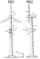
- FIG. 1 shows a wind turbine 23, on the mast 25 of which several wind turbines 10 according to the invention are attached.
- the wind turbines 10 according to the invention are horizontal arranged one above the other.
- the wind turbines according to the invention 10 are preferably below the vertically rotating Fixed rotor 24 to avoid wind turbulence.
- the wind turbines according to the invention consist of a annular rotor 17, as can be seen in Figures 3 and 5 is protected by a panel around the mast 25 turns. It can be seen from FIG. 1 that the paneling has a Has funnel-shaped air inlet that faces the wind becomes.
- the electricity generated by the wind turbines is in a transformer 26 that is regularly on the ground is arranged, converted to the required voltage and frequency.
- Figure 2 shows a side view of the device of the figure 1. This view shows a panel alignment 16 visible, the wind-controlled cladding like a flag 15 aligns.
- FIG. 3 is a detailed structure of the wind turbine 10 remove.
- This has the rotor 17, which is annular is so that it can rotate around the mast 25.
- At the Rotor blades 11 are attached to the outside of the rotor 17 are preferably spoon-shaped. Other forms are but also conceivable.
- Half of the rotor 17 is from the Surrounding 15, which is preferably a U-shaped Has cross section.
- the casing 15 is also rotatable stored and aligned depending on the wind direction 21 so that the rotor blades 11 which are opposed to the wind are protected.
- a possible storage of the cladding is shown in FIG. 9 remove.
- the panel 21 is preferably by a correspondingly large panel aligner 16, that looks like a flag.
- the Fairing aligner 16 is preferably on the rear Edge and the side of the panel 15 facing away from the wind attached.
- Figure 5 is another way of training the Remove panel 15.
- the rotor 17 becomes almost completely surrounded by the fairing.
- the panel points only one air inlet 28 through the above Medium is always aligned against the wind, and so arranged is that the wind directly into the rotor blades 11 of the Rotors 17 engages.
- the panel also has an air outlet 29 on.
- the panel 15 thus creates a pump or.
- the air inlet 28 is preferably funnel-shaped and has Air baffles 30 on the wind in the most optimal deflect as the rotor blades 11. Depending on the arrangement of the The wind should be redirected in the direction of rotation become. If the funnel as in the present case is arranged laterally, so the setting angle changes Air baffles 30 the closer they are to the center of the rotor 17 are.
- the Bearing consists of an L-shaped bearing ring 12 on which the rotor 17 is attached. Between the legs of the bearing ring 12 are bearings 27 arranged in the form of impellers in one oblique angles are arranged between the legs.
- the figure also shows the arrangement of a generator 19, the one without gear, directly via a friction wheel drive 31 is connected to the rotor 17.
- the rotor 17 is on an L-shaped Fixed bearing ring 12 which extends around the mast 25. Extend radially at an equiangular distance the mast 25 bearing 27, which are arranged on connecting struts 13 are.
- the bearings 27 are preferably at an angle of Arranged 45 ° and extend with their outer tread in the angle through the apex of the bearing ring 12 is formed.
- the bearing 27 is preferably an impeller educated.
- the connecting struts 13 are opposite to the bearing 27 Side connected to the mast 25.
- the arrangement of the generator 19 can also be seen in FIG. This is preferably arranged hanging under the rotor 17.
- the rotor 17 is through the L-shaped bearing ring a friction wheel drive 31, which is shown in more detail in FIG is connected to the generator 19.
- a gear shaft 20 of the generator 19 is either direct or via a gear 18 connected to a friction wheel 33.
- the friction wheel 33 will by a tensioning wheel 34 against the preferably the vertical Leg of the L-shaped bearing rings 12 pressed.
- the generator 19 is also through a connecting strut 13 to the mast 25 connected. Depending on the speed of the rotor 17, this can Friction wheel to be put on or not.
- the rotor 17 start rotating slightly without contact with the generator To have 19.
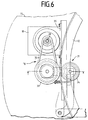
- FIG. 6 shows the detailed structure of the friction wheel drive 31 remove.
- the generator 19 is the friction wheel 33 and the Tensioning wheel 34 arranged on a frame 35, which in turn over a connecting strut 13 is connected to the mast 25.
- the friction wheel 33 is connected to the transmission shaft 20 via a belt 32 of the generator 19 connected. This allows certain gear ratios be predetermined.
- the friction wheel 33 will by spring force against the vertical leg of the L-shaped Bearing rings 12 pressed. To a corresponding friction wheel too will have the tension wheel 34 on the opposite side of the leg pressed with a spring against the friction wheel 33. This creates a pressure on both sides of the leg exercised, which enables a power transmission without friction losses.
- gears are also conceivable. So could well-known automatic transmissions are used which the generator always keep at an optimal number of revolutions. The These gears are controlled depending on the rotation of the rotor.
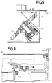
- the drive is shown in side view in FIG.
- the generator 19 is directly over its gear shaft 20 connected to the friction wheel.
- the tensioning wheel 34 is arranged so that pressure from both sides one leg is exerted on the vertical leg becomes.
- the friction wheels are preferably ball mounted.
- the Bearing ring formed in its inside gear-shaped to to drive a second gear.
- the second gear is e.g. connected to the generator 19 via a gear shaft 20.
- the generator 19 could also be integrated directly in the rotor 17 be so that the rotor 17 and the bearing ring 12 in interaction have the effect of a generator.
- Figure 8 is a detailed view of the storage.
- Bearing 27 shaped as a wheel, the axis of which at an angle of 45 ° is arranged.
- the wheel is supported on two ball bearings, which are arranged in a housing which is mounted on a frame 36 is attached.
- the frame 36 is in turn with a connecting strut 13 connected.
- the tread of the wheel is preferred trending so that the treads in the angle formed by the legs of the L-shaped bearing ring fit snugly.
- Figure 9 shows the storage of the fairing 15 on the rotor 17.
- two ball bearings 38, 39 at an angle of 90 ° to each other, each on the leg of an also L-shaped bearing ring 37.
- Camps 38, 39 are attached to the panel 15. That kind of Storage is multiple on the rotor 17 in orbit Lagerings 37 arranged, which is connected to the panel 15 is.
- the housing can also be supported as shown in the figure 4 can be removed.
- both the rotor 17 and the bearing ring 12 are divisible so that they can be guided around an existing mast 25.
- the division preferably takes place in segments of the same size.
- variable connecting struts 13 connect the bearings 27 to the mast 25. They can be different Lengths to match the differing mast thicknesses To take into account.
- the retrofitted wind turbine can already do one use existing transformer 26 to recover the Feed energy into the public grid.
Landscapes
- Engineering & Computer Science (AREA)
- Life Sciences & Earth Sciences (AREA)
- Sustainable Development (AREA)
- Sustainable Energy (AREA)
- Chemical & Material Sciences (AREA)
- Combustion & Propulsion (AREA)
- Mechanical Engineering (AREA)
- General Engineering & Computer Science (AREA)
- Power Engineering (AREA)
- Wind Motors (AREA)
Applications Claiming Priority (2)
| Application Number | Priority Date | Filing Date | Title |
|---|---|---|---|
| DE19853790A DE19853790A1 (de) | 1998-11-21 | 1998-11-21 | Windkraftanlage |
| DE19853790 | 1998-11-21 |
Publications (2)
| Publication Number | Publication Date |
|---|---|
| EP1002949A2 true EP1002949A2 (fr) | 2000-05-24 |
| EP1002949A3 EP1002949A3 (fr) | 2001-12-05 |
Family
ID=7888585
Family Applications (1)
| Application Number | Title | Priority Date | Filing Date |
|---|---|---|---|
| EP99118279A Withdrawn EP1002949A3 (fr) | 1998-11-21 | 1999-09-15 | Eolienne à axe vertical |
Country Status (4)
| Country | Link |
|---|---|
| US (1) | US6270308B1 (fr) |
| EP (1) | EP1002949A3 (fr) |
| JP (1) | JP2000161197A (fr) |
| DE (1) | DE19853790A1 (fr) |
Cited By (5)
| Publication number | Priority date | Publication date | Assignee | Title |
|---|---|---|---|---|
| EP1704325A4 (fr) * | 2003-12-31 | 2010-09-15 | Envision Corp | Moteur de turbine eolienne structure de rotor horizontal |
| ITMI20090551A1 (it) * | 2009-04-07 | 2010-10-08 | Claudio Antolini | Dispositivo per prevenire l'effetto frenante delle pale avanzanti controvento nei generatori eolici ad asse verticale e generatore eolico provvisto di tale dispositivo |
| WO2010137929A1 (fr) * | 2009-05-25 | 2010-12-02 | Abuzed Nagi Dabbab | Moyen de protection pour turbine éolienne |
| NL2006276C2 (nl) * | 2011-02-22 | 2012-08-24 | Itomforce Innovations B V | Constructie met meervoudige windturbine. |
| DE102017002015B4 (de) * | 2017-03-03 | 2019-10-31 | Luis Manuel Amores Pamies | Energieerzeugungsvorrichtung |
Families Citing this family (66)
| Publication number | Priority date | Publication date | Assignee | Title |
|---|---|---|---|---|
| CA2424334C (fr) * | 2000-09-27 | 2008-07-22 | Allan P. Henderson | Fondation a lestage peripherique pour eoliennes et analogues |
| DE10120181A1 (de) * | 2001-04-24 | 2002-11-07 | Wilhelm Groppel | Windkraftanlage |
| DE10145414B4 (de) * | 2001-09-14 | 2013-09-12 | Aloys Wobben | Verfahren zur Errichtung einer Windenergieanlage, Windenergieanlage |
| CA98844S (en) | 2001-10-19 | 2003-06-17 | Kbe Windpower Gmbh | Wind force turbine |
| ATE441030T1 (de) * | 2002-03-08 | 2009-09-15 | Ocean Wind Energy Systems | Offshore-windenergieanlage |
| USD517986S1 (en) * | 2002-06-06 | 2006-03-28 | Aloys Wobben | Wind turbine and rotor blade of a wind turbine |
| US7533505B2 (en) | 2003-01-06 | 2009-05-19 | Henderson Allan P | Pile anchor foundation |
| BRPI0406933B1 (pt) * | 2003-02-01 | 2014-04-08 | Aloys Wobben | Instalação de energia eólica, e, processo para a montagem da mesma |
| DE10339438C5 (de) * | 2003-08-25 | 2011-09-15 | Repower Systems Ag | Turm für eine Windenergieanlage |
| US6981839B2 (en) | 2004-03-09 | 2006-01-03 | Leon Fan | Wind powered turbine in a tunnel |
| US6856042B1 (en) * | 2003-10-09 | 2005-02-15 | Hisaomi Kubota | Wind turbine generator |
| US7618217B2 (en) * | 2003-12-15 | 2009-11-17 | Henderson Allan P | Post-tension pile anchor foundation and method therefor |
| US7215037B2 (en) * | 2004-11-19 | 2007-05-08 | Saverio Scalzi | Protective wind energy conversion chamber |
| US8181724B2 (en) * | 2004-11-22 | 2012-05-22 | Yang Cong | Motor vehicles |
| US8240416B2 (en) * | 2004-11-22 | 2012-08-14 | Yang Cong | Motor vehicles |
| US20100122855A1 (en) * | 2004-11-22 | 2010-05-20 | Yang Cong | Motor Vehicles |
| CN1603613A (zh) * | 2004-11-22 | 2005-04-06 | 丛洋 | 风气发动机即采用风力气压取代燃料能源的发动机 |
| US20100122857A1 (en) * | 2004-11-22 | 2010-05-20 | Yang Cong | Motor Vehicles |
| US8177002B2 (en) * | 2004-11-22 | 2012-05-15 | Yang Cong | Motor vehicles |
| CN101639046B (zh) * | 2004-11-22 | 2012-10-17 | 丛洋 | 专用于风气发动机机动车的喷气系统 |
| US20100101874A1 (en) * | 2004-11-22 | 2010-04-29 | Yang Cong | Motor Vehicles |
| MX2007006101A (es) * | 2004-11-22 | 2007-07-11 | Yang Cong | Motor y vehiculo de motor de viento neumatico. |
| US7980825B2 (en) * | 2005-10-18 | 2011-07-19 | Robert A. Vanderhye | Savonius rotor blade construction particularly for a three bladed savonius rotor |
| CN100564869C (zh) * | 2005-04-08 | 2009-12-02 | 邱垂南 | 飞轮风力转换装置 |
| RU2364749C2 (ru) * | 2005-04-08 | 2009-08-20 | Чуй-Нань ЧИО | Устройство для преобразования энергии ветра с приводом от маховика |
| US7633177B2 (en) * | 2005-04-14 | 2009-12-15 | Natural Forces, Llc | Reduced friction wind turbine apparatus and method |
| DE102005029478A1 (de) * | 2005-06-24 | 2006-12-28 | Alexander Faller Sen. | Duplex-Windkraftanlage |
| EP1854999A1 (fr) * | 2006-05-12 | 2007-11-14 | Mass Metropolitan International AG | Éolienne |
| US20100001532A1 (en) * | 2006-06-12 | 2010-01-07 | Mihai Grumazescu | Wind-driven turbine cells and arrays |
| ZA200901360B (en) * | 2006-08-16 | 2010-05-26 | Yang Cong | Wind-gas engine assembly and motor vehicle with the same |
| GB2444557A (en) * | 2006-12-08 | 2008-06-11 | Anthony William Birmingham | Wind turbine with funnel inlet |
| JP5002309B2 (ja) * | 2007-04-06 | 2012-08-15 | 富士重工業株式会社 | 水平軸風車 |
| USD602860S1 (en) * | 2007-06-14 | 2009-10-27 | Greenergy India Private Limited | Wind turbine |
| USD639240S1 (en) | 2007-07-23 | 2011-06-07 | Aloys Wobben | Wind turbine |
| USD584686S1 (en) | 2007-07-23 | 2009-01-13 | Aloys Wobben | Nacelle of a wind turbine |
| WO2009056898A1 (fr) * | 2007-11-02 | 2009-05-07 | Alejandro Cortina-Cordero | Tour en béton postcontraint pour génératrices éoliennes |
| CN101821500A (zh) * | 2007-10-05 | 2010-09-01 | 维斯塔斯风力系统有限公司 | 用于给风轮机的叶片除冰的方法、风轮机及其使用 |
| US20090191057A1 (en) * | 2008-01-24 | 2009-07-30 | Knutson Roger C | Multi-Axis Wind Turbine With Power Concentrator Sail |
| GB2457772A (en) * | 2008-02-29 | 2009-09-02 | Hopewell Wind Power Ltd | Wind turbine wind deflector. |
| US20090261596A1 (en) * | 2008-04-17 | 2009-10-22 | Windenergy Co., Ltd. | Wind power generator |
| US20100024311A1 (en) * | 2008-07-30 | 2010-02-04 | Dustin Jon Wambeke | Wind turbine assembly with tower mount |
| USD602861S1 (en) * | 2008-08-27 | 2009-10-27 | Talab Patrick H | Wind turbine |
| US8198748B1 (en) * | 2008-11-14 | 2012-06-12 | Victor Korzen | Magnetically levitated linear barrel generator |
| US8368243B1 (en) | 2008-12-19 | 2013-02-05 | Holden Harold H | Roofline conduit for wind generator |
| GB0904816D0 (en) | 2009-03-20 | 2009-05-06 | Revoluter Ltd | Turbine assembly |
| US8109727B2 (en) * | 2009-04-20 | 2012-02-07 | Barber Gerald L | Wind turbine |
| KR101100037B1 (ko) * | 2009-07-08 | 2011-12-30 | 최혁선 | 풍력터빈장치 |
| US8564154B2 (en) | 2010-06-24 | 2013-10-22 | BT Patent LLC | Wind turbines with diffusers for the buildings or structures |
| JP5449060B2 (ja) | 2010-06-30 | 2014-03-19 | 三菱重工業株式会社 | 風力発電装置 |
| USD654433S1 (en) * | 2011-03-04 | 2012-02-21 | Delta Electronics, Inc. | Wind power generator |
| USD665739S1 (en) * | 2011-05-31 | 2012-08-21 | Envision Energy (Denmark) Aps | Blade |
| USD665352S1 (en) * | 2011-09-30 | 2012-08-14 | Enel Green Power S.P.A. | Wind turbine generator part |
| GB201117554D0 (en) * | 2011-10-11 | 2011-11-23 | Moorfield Tidal Power Ltd | Tidal stream generator |
| MX2012000581A (es) * | 2012-01-12 | 2013-07-12 | Jose Luis Santana Macias | Turbina eólica de eje vertical con deflector envolvente escalable polivalente con acoplamientos independientes. |
| CA147876S (en) | 2012-04-11 | 2013-09-27 | Wobben Properties Gmbh | Wind turbine rotor blade |
| USD760165S1 (en) | 2013-07-01 | 2016-06-28 | Marmen Inc | Tower |
| USD750560S1 (en) | 2013-04-11 | 2016-03-01 | Wobben Properties Gmbh | Wind turbine blade |
| ITBO20130423A1 (it) * | 2013-07-31 | 2015-02-01 | Sandra Castaldini | Generatore ausiliario di energia elettrica. |
| US20150108758A1 (en) * | 2013-10-23 | 2015-04-23 | Thomas W. Oakes | Turbine system and method constructed for efficient low fluid flow rate operation |
| DE102014014199A1 (de) | 2014-09-16 | 2016-03-17 | Silvio Sgroi | Windkraftanlage |
| GB2536618B (en) | 2015-03-09 | 2019-03-06 | Bell Gordon | Air capture turbine |
| US20170234302A1 (en) * | 2015-11-25 | 2017-08-17 | Hattar Tanin LLC | Innovative wind turbine construction for 100% energy independence or even being energy positive |
| FR3053083B1 (fr) * | 2016-06-22 | 2019-11-01 | Safran Aircraft Engines | Anneau de carenage de roue a aubes |
| DE102017126691A1 (de) | 2017-11-14 | 2019-05-16 | Dieter Hurnik | Windkraftanlage |
| DE102022121775A1 (de) | 2022-08-29 | 2024-02-29 | Evers Holding & Consulting GmbH | Windkraftanlage |
| CN119532102A (zh) * | 2024-09-27 | 2025-02-28 | 吉电(滁州)章广风力发电有限公司 | 一种风力发电机扇叶 |
Citations (6)
| Publication number | Priority date | Publication date | Assignee | Title |
|---|---|---|---|---|
| DE2620862A1 (de) | 1976-05-11 | 1977-11-17 | Otto Schlapp | Windkraftwerk in turmbauweise mit senkrechten rotoren zur windnutzung, die mit zusaetzlich angeordneten windnutzungsfluegeln oder windraedern mit waagrechten wellen, an gemeinsamen windkraftnutzungsstellen zusammenwirken |
| GB2041457A (en) | 1978-12-15 | 1980-09-10 | Mihajlovic V | Wind motor |
| DE3829112A1 (de) | 1988-08-27 | 1990-03-01 | Joern Martens | Windkraftanlage |
| DD296734A5 (de) | 1990-07-18 | 1991-12-12 | Joachim Poenisch,De | Einrichtung zur erzeugung von elektroenergie aus windkraft |
| DE19615943A1 (de) | 1996-04-22 | 1997-10-23 | Uwe Kochanneck | Solaranlage |
| DE19648632A1 (de) | 1996-10-17 | 1998-04-23 | Burger Helmut | Windkraftanlage zur Umsetzung von Windenergie in elektrische Energie in horizontaler und vertikaler Ausführung |
Family Cites Families (13)
| Publication number | Priority date | Publication date | Assignee | Title |
|---|---|---|---|---|
| US1712149A (en) * | 1926-05-13 | 1929-05-07 | Kolozsy Louis | Wind-power mechanism |
| FR946724A (fr) * | 1947-05-09 | 1949-06-13 | Perfectionnement à la distribution du fluide sur des roues aériennes ou hydrauliques, réceptrices ou motrices | |
| US4031173A (en) * | 1976-03-25 | 1977-06-21 | Paul Rogers | Efficiency and utilization of cooling towers |
| US4134707A (en) * | 1977-04-26 | 1979-01-16 | Ewers Marion H | Wind turbine apparatus |
| US4156580A (en) * | 1977-08-18 | 1979-05-29 | Pohl Lothar L | Wind-turbines |
| DE2757266C2 (de) * | 1977-12-22 | 1979-07-05 | Dornier Gmbh, 7990 Friedrichshafen | Windturbinenanlage mit Hauptrotor und einem oder mehreren Anlaufhilferotoren |
| US4281965A (en) * | 1979-05-07 | 1981-08-04 | Stjernholm Dale T | Cantilever mounted wind turbine |
| US4329593A (en) * | 1980-09-10 | 1982-05-11 | Willmouth Robert W | Wind energy machine utilizing cup impellers |
| US4350900A (en) * | 1980-11-10 | 1982-09-21 | Baughman Harold E | Wind energy machine |
| GB2168763A (en) * | 1984-12-19 | 1986-06-25 | Anthony Close | Vertically mounted wind generator |
| DE3529883A1 (de) * | 1985-08-21 | 1987-02-26 | Alwin Traub | Windkraftanlage lamellenkarussell |
| GB9024500D0 (en) * | 1990-11-10 | 1991-01-02 | Peace Steven J | A vertical axis wind turbine unit capable of being mounted on or to an existing chimney,tower or similar structure |
| WO1997039240A1 (fr) * | 1996-04-12 | 1997-10-23 | Horst Bendix | Cheminee mise hors service servant de tour pour une turbine eolienne |
-
1998
- 1998-11-21 DE DE19853790A patent/DE19853790A1/de not_active Withdrawn
-
1999
- 1999-09-15 EP EP99118279A patent/EP1002949A3/fr not_active Withdrawn
- 1999-11-11 US US09/438,757 patent/US6270308B1/en not_active Expired - Fee Related
- 1999-11-16 JP JP11324979A patent/JP2000161197A/ja active Pending
Patent Citations (6)
| Publication number | Priority date | Publication date | Assignee | Title |
|---|---|---|---|---|
| DE2620862A1 (de) | 1976-05-11 | 1977-11-17 | Otto Schlapp | Windkraftwerk in turmbauweise mit senkrechten rotoren zur windnutzung, die mit zusaetzlich angeordneten windnutzungsfluegeln oder windraedern mit waagrechten wellen, an gemeinsamen windkraftnutzungsstellen zusammenwirken |
| GB2041457A (en) | 1978-12-15 | 1980-09-10 | Mihajlovic V | Wind motor |
| DE3829112A1 (de) | 1988-08-27 | 1990-03-01 | Joern Martens | Windkraftanlage |
| DD296734A5 (de) | 1990-07-18 | 1991-12-12 | Joachim Poenisch,De | Einrichtung zur erzeugung von elektroenergie aus windkraft |
| DE19615943A1 (de) | 1996-04-22 | 1997-10-23 | Uwe Kochanneck | Solaranlage |
| DE19648632A1 (de) | 1996-10-17 | 1998-04-23 | Burger Helmut | Windkraftanlage zur Umsetzung von Windenergie in elektrische Energie in horizontaler und vertikaler Ausführung |
Cited By (6)
| Publication number | Priority date | Publication date | Assignee | Title |
|---|---|---|---|---|
| EP1704325A4 (fr) * | 2003-12-31 | 2010-09-15 | Envision Corp | Moteur de turbine eolienne structure de rotor horizontal |
| ITMI20090551A1 (it) * | 2009-04-07 | 2010-10-08 | Claudio Antolini | Dispositivo per prevenire l'effetto frenante delle pale avanzanti controvento nei generatori eolici ad asse verticale e generatore eolico provvisto di tale dispositivo |
| WO2010137929A1 (fr) * | 2009-05-25 | 2010-12-02 | Abuzed Nagi Dabbab | Moyen de protection pour turbine éolienne |
| NL2006276C2 (nl) * | 2011-02-22 | 2012-08-24 | Itomforce Innovations B V | Constructie met meervoudige windturbine. |
| WO2012115512A1 (fr) * | 2011-02-22 | 2012-08-30 | Itomforce Innovations B.V. | Construction dotée de multiples éoliennes |
| DE102017002015B4 (de) * | 2017-03-03 | 2019-10-31 | Luis Manuel Amores Pamies | Energieerzeugungsvorrichtung |
Also Published As
| Publication number | Publication date |
|---|---|
| EP1002949A3 (fr) | 2001-12-05 |
| JP2000161197A (ja) | 2000-06-13 |
| DE19853790A1 (de) | 2000-05-31 |
| US6270308B1 (en) | 2001-08-07 |
Similar Documents
| Publication | Publication Date | Title |
|---|---|---|
| EP1002949A2 (fr) | Eolienne à axe vertical | |
| EP1440240B1 (fr) | Generateur pour une centrale hydroelectrique | |
| DE102008037609A1 (de) | Rotorflügel mit mehreren Abschnitten für Windkraftanlagen und Windkraftanlagen mit diesen | |
| EP2395232B1 (fr) | Turbine orthogonale basse pression | |
| DE102019100208A1 (de) | Vertikale Windenergieanlage | |
| DE112017004377B4 (de) | Windturbinenanlage | |
| WO2010124778A2 (fr) | Centrale électrique immergée équipée d'une turbine hydraulique tournant dans le même sens et à écoulement bidirectionnel | |
| DE19823473A1 (de) | Strömungsenergieanlage | |
| DE202012013307U1 (de) | Windkraftanlage und Turbinenlaufrad hierfür | |
| DE2444803A1 (de) | Turbine zur umwandlung der energie eines stroemenden mediums in elektrische oder mechanische energie mit hoechstem wirkungsgrad | |
| EP1702159A1 (fr) | Turbine eolienne a enveloppe | |
| DE102009060895A1 (de) | Windkraftanlage mit einem ersten Rotor | |
| EP2636892A2 (fr) | Installation éolienne et procédé de production d'énergie rotative par le vent | |
| DE19807193C1 (de) | Windkraftanlage in Schnelläuferausführung | |
| DE102010032223A1 (de) | Energiegewinnungsanlage | |
| DE102013216334A1 (de) | Drehmomentübertragendes Bauteil eines Getriebes | |
| DE102010024621B4 (de) | Energiewandler | |
| DE202020000307U1 (de) | Vertikale Windenergieanlage | |
| EP1507973B1 (fr) | Turbine eolienne a gaine | |
| EP3807517B1 (fr) | Turbine | |
| DE102011050462A1 (de) | Windkraftanlage | |
| EP3500750A1 (fr) | Éolienne comprenant un rotor vertical et une structure formant face d'entrée | |
| DE102017127787A1 (de) | Vertikalwindkraftanlage | |
| DE102017002015B4 (de) | Energieerzeugungsvorrichtung | |
| WO2011160688A1 (fr) | Éolienne |
Legal Events
| Date | Code | Title | Description |
|---|---|---|---|
| PUAI | Public reference made under article 153(3) epc to a published international application that has entered the european phase |
Free format text: ORIGINAL CODE: 0009012 |
|
| AK | Designated contracting states |
Kind code of ref document: A2 Designated state(s): AT BE CH CY DE DK ES FI FR GB GR IE IT LI LU MC NL PT SE |
|
| AX | Request for extension of the european patent |
Free format text: AL;LT;LV;MK;RO;SI |
|
| PUAL | Search report despatched |
Free format text: ORIGINAL CODE: 0009013 |
|
| AK | Designated contracting states |
Kind code of ref document: A3 Designated state(s): AT BE CH CY DE DK ES FI FR GB GR IE IT LI LU MC NL PT SE |
|
| AX | Request for extension of the european patent |
Free format text: AL;LT;LV;MK;RO;SI |
|
| AKX | Designation fees paid | ||
| REG | Reference to a national code |
Ref country code: DE Ref legal event code: 8566 |
|
| STAA | Information on the status of an ep patent application or granted ep patent |
Free format text: STATUS: THE APPLICATION IS DEEMED TO BE WITHDRAWN |
|
| 18D | Application deemed to be withdrawn |
Effective date: 20020606 |