EP1003040A2 - Drehsensor - Google Patents
Drehsensor Download PDFInfo
- Publication number
- EP1003040A2 EP1003040A2 EP99308962A EP99308962A EP1003040A2 EP 1003040 A2 EP1003040 A2 EP 1003040A2 EP 99308962 A EP99308962 A EP 99308962A EP 99308962 A EP99308962 A EP 99308962A EP 1003040 A2 EP1003040 A2 EP 1003040A2
- Authority
- EP
- European Patent Office
- Prior art keywords
- supporting member
- rotor
- rotation sensor
- detecting
- rotation
- Prior art date
- Legal status (The legal status is an assumption and is not a legal conclusion. Google has not performed a legal analysis and makes no representation as to the accuracy of the status listed.)
- Granted
Links
- 238000001514 detection method Methods 0.000 claims abstract description 15
- 229920003002 synthetic resin Polymers 0.000 claims description 6
- 239000000057 synthetic resin Substances 0.000 claims description 6
- 230000005389 magnetism Effects 0.000 claims description 5
- 239000002184 metal Substances 0.000 claims description 2
- 229910052751 metal Inorganic materials 0.000 claims description 2
- 238000004873 anchoring Methods 0.000 description 4
- XEEYBQQBJWHFJM-UHFFFAOYSA-N Iron Chemical compound [Fe] XEEYBQQBJWHFJM-UHFFFAOYSA-N 0.000 description 2
- 238000010276 construction Methods 0.000 description 2
- 238000010586 diagram Methods 0.000 description 2
- 238000002310 reflectometry Methods 0.000 description 2
- 210000000078 claw Anatomy 0.000 description 1
- 230000003247 decreasing effect Effects 0.000 description 1
- 230000002708 enhancing effect Effects 0.000 description 1
- 230000004907 flux Effects 0.000 description 1
- 229910052742 iron Inorganic materials 0.000 description 1
- 238000005476 soldering Methods 0.000 description 1
Images


Classifications
-
- G—PHYSICS
- G01—MEASURING; TESTING
- G01P—MEASURING LINEAR OR ANGULAR SPEED, ACCELERATION, DECELERATION, OR SHOCK; INDICATING PRESENCE, ABSENCE, OR DIRECTION, OF MOVEMENT
- G01P3/00—Measuring linear or angular speed; Measuring differences of linear or angular speeds
- G01P3/42—Devices characterised by the use of electric or magnetic means
- G01P3/44—Devices characterised by the use of electric or magnetic means for measuring angular speed
- G01P3/48—Devices characterised by the use of electric or magnetic means for measuring angular speed by measuring frequency of generated current or voltage
- G01P3/481—Devices characterised by the use of electric or magnetic means for measuring angular speed by measuring frequency of generated current or voltage of pulse signals
- G01P3/487—Devices characterised by the use of electric or magnetic means for measuring angular speed by measuring frequency of generated current or voltage of pulse signals delivered by rotating magnets
-
- G—PHYSICS
- G01—MEASURING; TESTING
- G01P—MEASURING LINEAR OR ANGULAR SPEED, ACCELERATION, DECELERATION, OR SHOCK; INDICATING PRESENCE, ABSENCE, OR DIRECTION, OF MOVEMENT
- G01P1/00—Details of instruments
- G01P1/02—Housings
- G01P1/026—Housings for speed measuring devices, e.g. pulse generator
Definitions
- the present invention relates to a rotation sensor such as a throttle position sensor, attached to a throttle valve, for detecting an opening level of the valve, and more particularly to a rotation sensor accommodable to the eccentricity of a rotation portion of the valve relative to the rotating shaft of the sensor.
- Fig. 23 is a schematic diagram showing a conventional rotation sensor as described above.
- a shaft 52 is coupled to a rotor 51 of a detection side, the shaft 52 is rotatably supported at a location of a bearing 53, and a magnetized code plate 54 is integrally at the tip of the shaft 52.
- a magnetism detecting element 55 In the vicinity of the circumference of the code plate 54 is disposed a magnetism detecting element 55, which is supported by a casing not shown.
- the conventional rotation sensor which has a so-called one-point support configuration in which the shaft 52 is supported at one point, has the shaft 52 supported by the bearing 53 with some backlash so that it is freely rotatable. Therefore, when the rotor 51 is attached to the shaft 52 with their center axes in misalignment or the rotor 51 itself rotates eccentrically, if the code plate 54 rotates via the shaft 52 as the rotor 51 rotates, since the code plate 54 rotates eccentrically, a gap G between the code plate and the magnetism detecting element 55 changes greatly and therefore a linear output is not obtained in a magnetic variable resistor. This has been a disadvantage of conventional rotation sensors.
- An object of the present invention is to solve these disadvantages of the related art and provide a highly reliable rotation sensor capable of correctly detecting rotation states.
- the present invention provides a rotation sensor comprising:
- both the rotor and the detecting member for detecting a rotation state thereof are supported by the first supporting member and the rotor and the detecting member are movable together in the X and Y directions, even if the rotation portion becomes eccentric, the rotor and the detecting member together can follow the eccentricity and the spacing between the rotor and the detecting member is always constant, and therefore there is no output variation due to the eccentricity of the rotation portion.
- the rotation sensor includes
- both the first supporting member and the third supporting member are constructed from a synthetic resin and the second supporting member is constructed from metal, friction resistance is reduced and the rotation sensor moves smoothly in the X and Y directions, so that it can detect a rotation state more correctly.
- the Y-direction guide means which permits the travel of the first supporting member in the Y direction and prevents the travel thereof in the X direction is provided in the second supporting member
- X-direction guide means which permits the travel of the second supporting member in the X direction and prevents the travel thereof in the Y direction is provided in the third supporting member, whereby the travel in the X and Y directions is distinctly divided so that the rotation sensor can respond appropriately to the eccentricity of a rotation portion.
- the third supporting member is formed with an exterior member of the sensor in a fixed state, the third supporting member need not be provided additionally, so that parts can be reduced in quantity, size, and weight.
- a terminal is provided in the third supporting member, and the terminal and the detecting member are connected by a flexible connecting wire, whereby the first supporting member moves without trouble and a rotation state can be correctly detected.
- a concave housing part is formed in the first supporting member and the detecting member is inserted and secured within the housing member, and thereby the detecting member is disposed close to the rotor, so that correct detection of a rotation state can be made and the detecting member does not project substantially from the first supporting member, providing no obstacle for the travel of the first supporting member.
- the first supporting member is of shape of almost rectangular frame and is disposed in sliding on the second supporting member, the first supporting member moves stably.
- the rotor has a magnetized portion on the circumferential side and the detecting member is a magnetism detecting element, the reliability of detection is high and the configuration of the detection part is simple and inexpensive.
- a rotation part of a detection side is a throttle valve, there can be provided a highly reliable throttle position sensor capable of correct detection of a rotation state.
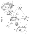
- Fig. 1 is an exploded perspective view showing a rough shape of a rotation sensor according to the present invention.
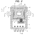
- Fig. 2 is a front cross-sectional view of the rotation sensor.
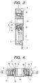
- Fig. 3 is a cross-sectional view taken along the line 3-3 of Fig. 2.
- Fig. 4 is a cross-sectional view taken along the line 4-4 of Fig. 2.
- Fig. 5 is a front view of a housing used in the rotation sensor.
- Fig. 6 is a vertical cross-sectional view of the housing.
- Fig. 7 is a horizontal cross-sectional view of the housing.
- Fig. 8 is a front view of a rotor used in the rotation sensor.
- Fig. 9 is a vertical cross-sectional view of the rotor.
- Fig. 10 is a side view of the rotor.
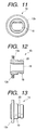
- Fig. 11 is a front view of a core supporter used in the rotation sensor.
- Fig. 12 is a vertical cross-sectional view of the core supporter.
- Fig. 13 is a side view of the core supporter.
- Fig. 14 is a front cross-sectional view of a first supporter used in the rotation sensor.
- Fig. 15 is a cross-sectional view taken along the line 15-15 of Fig. 14.
- Fig. 16 is a cross-sectional view taken along the line 16-16 of Fig. 14.
- Fig. 17 is a side view of the first supporter.
- Fig. 18 is a bottom view of the first supporter.
- Fig. 19 is a front view of a second supporter used in the rotation sensor.
- Fig. 20 is a cross-sectional view taken along the line 20-20 of Fig. 19.
- Fig. 21 is a cross-sectional view taken along the line 21-21 of Fig. 19.
- Fig. 22 is a side view of the second supporter.
- Fig. 23 is a schematic diagram showing a conventional rotation sensor.
- Fig. 1 is a perspective view showing a rough shape of a rotation sensor according to the embodiment
- Fig. 2 is a front cross-sectional view of the rotation sensor
- Fig. 3 is a cross-sectional view taken along the line 3-3 of Fig. 2
- Fig. 4 is a cross-sectional view taken along the line 4-4 of Fig. 2.
- the reference numeral 1 denotes a housing and 2 denotes a printed wiring board, which is disposed within the housing 1 and connected to plural terminals 3 fitted to the housing 1 as shown in Figs. 2 and 3.
- the reference numeral 4 denotes an almost cylindrical rotor; 5, a first supporting member of almost frame shape; 6, three detecting members each consisting of a hole IC, secured to the first supporting member 5; 7, a flexible printed wiring board of almost T-character shape, with the three detecting members 6 soldered, connected to the printed wiring board 2; 8, a second supporting member; and 9, a cover of almost plate shape.
- Figs. 5, 6, and 7 are a front view, a vertical cross-sectional view, and a horizontal cross-sectional view of the housing 1, respectively.
- the housing 1 constructed from a synthetic resin which is of almost box shape, has a concave housing part 10 formed inside it and a through hole 11 provided at a position corresponding to the bottom of the concave housing part 10.
- guide stage parts 12 which extend in parallel to the X direction, and a third supporting member is formed by supporting the second supporting member 8 movably in the X direction by the guide stage part 12.
- Figs. 8, 9, and 10 are a front view, a vertical cross-sectional view, and a side view of the rotor 4, respectively.
- Figs. 11, 12, and 13 are a front view, a vertical cross-sectional view, and a side view of a core supporting member 13 used for the rotor 4, respectively.
- the rotor 4 comprises a core supporter 13, a core ring 14 supported thereby, a magnetic shield ring 15, and a core ring supporting member 16 for supporting the core ring 14 to the core supporter 13.
- the core supporter 13 is constructed from a synthetic resin which is of almost cylindrical shape, and has a non-circular engagement hole 18 formed inside it, through which a rotating shaft 17 (e.g., a metallic rotating shaft connected to a throttle valve. See Figs. 1 and 9), a rotor of a detection side, is fitted.
- a magnetic shield ring 15 On the cylindrical part 19 of the core supporter 13 are successively fitted a magnetic shield ring 15, a core ring 14, and a core ring supporting member 16.
- a concave part 13a provided in the flange of the core supporter 13 and a projected part 14a provided in the core ring 14 engage with each other to determine the position of a rotation direction.
- An anchoring groove 20 of circular ring shape is formed on the circumferential side of the cylindrical part 19
- a projection part 16a inserted in the anchoring groove 20 is provided on the inner circumferential side of the core ring supporting member 16, and the engagement of the anchoring groove 20 and the projection part 16a causes the core ring 14 to rotate integrally while being supported in a sandwiched form between the core supporter 13 and the core ring supporting member 16.
- the core ring 14, which is constructed from, e.g., a plastic magnet, although not shown, is magnetized to the N or S pole on the circumferential side of the core ring 14 to maintain a proper
- the above described magnetic shield ring 15 is provided to prevent a situation in which a rotating shaft constructed from magnetic members such as iron exerts an influence on a flux distribution of the core ring 14 and output changes depending on the existence of the rotating shaft (because a reference value is determined in the state in which no rotating shaft exists) and the shape thereof, so that a reference value is not obtained.
- Fig. 14 is a front cross-sectional view of the first supporter 5; Fig. 15, a cross-sectional view taken along the line 15-15 of Fig. 14; Fig. 16, a cross-sectional view taken along the line 16-16 of Fig. 14; and Figs. 17 and 18 are a side view and a bottom view of the first supporter 5, respectively.
- the first supporter 5 is constructed from a synthetic resin and has a frame part 21 of almost rectangular shape, and has a housing part 22 at the center of the front to house most of the rotor 4, as shown in Fig. 14.
- Element securing parts 23 are concavely mounted, groove parts 23a are continuously provided, the terminals of the detecting members 6 are guided, and small holes 24 are formed in positions opposite to the housing part 22 of the element securing parts 23.
- each detecting member 6 is completely buried in the housing part 22.
- a projection 21a is provided at the bottom of the housing part 22, a flexible printed board 7 is fitted, and both are integrated so that no stress is applied to the soldering parts of the detecting members 6 as the supporter 5 moves.
- each detecting member 6 is disposed in opposed relation to and close to a magnetized portion of the core ring 14 via a small hole 24.
- Fig. 19 is a front view of the second supporter 8; Fig. 20, a cross-sectional view taken along the line 20-20 of Fig. 19; Fig. 21, a cross-sectional view taken along the line 21-21 of Fig. 19; and Fig. 22, a side view of the second supporter 8.
- the second supporter 8 is constructed from a synthetic resin, is rectangular in front shape, has a through hole 26 formed at the central portion thereof, and has guide walls 27 provided in the both sides which extend backward. As shown in Figs. 4, 19, and 21, a first supporter 5 is supported with some press between the guide walls 27 in both sides, but since a side opposite to the base is open, the supporter 8 can bend and move vertically without backlash in the X direction, that is, is supported movably in the Y direction as shown in Fig. 2.
- L-shaped holes 8a extending between the base forming the through hole 26 and the guide walls 27 are provided at the four corners, so that the supporter 8 can bend slightly in the Y direction and is supported in a sandwiched form without backlash between the guide stages 12.
- Projected parts 8b are formed along the X direction on the back of the base, so that the supporter 8 can move without backlash in the Y direction and smoothly in the X direction.
- a through hole 29 is formed at a predetermined position of the cover 9.
- the rotor 4 is supported rotatably by the first supporter 5 as shown by the dotted arrow in Fig. 1, the first supporter 5 is supported movably by the second supporter 8 only in the Y direction orthogonal to the rotating shaft direction of the rotor 4, the second supporter 8 is supported movably by the housing 1 (a third supporter) only in the X direction orthogonal to the rotating shaft direction of the rotor 4, a snap foot 9a of the cover 9 engages with a projection la on the side of the housing 1 to support the supporter 8, and the openings of the housing 1 are covered with the cover 9.
- the core supporter 13 (cylindrical part 19) is loosely inserted around it in the through hole 11 of the housing 1, the through hole 26 of the second supporter 8, and the through hole 29 of the cover 9, and extends outward from the housing 1 and the cover 9.
- the rotating shaft 17 is inserted and engaged in the engagement hole 18 of the core supporter 13, and the rotor 4 rotates together with the rotating shaft 17, while the first supporter 5 is prevented from rotating by the second supporter 8 and the housing 1 (third supporter).
- a rotation state of the rotating shaft 17 is detected and outputted using a magnetic variable resistor by plural detecting members (hole ICs) via the rotor 4 (core ring 14).
- the first supporter can also be cylindrical in shape, if the shape of the first supporter is rectangular as in the above described embodiment, since the first supporter contacts with the second supporter in four locations, a high dimensional accuracy is obtained, so that the first supporter can be supported stably without backlash.
- the housing is used also as the third supporter in the above described embodiment, the present invention is not limited to the above embodiment.
- an exterior member of the sensor in another fixed state such as the cover can also be used as a third supporter.
- the rotor is provided with a magnetized portion and a hole IC is used in the detecting member to magnetically detect a rotation state.
- the present invention is not limited to the above embodiment.
- a rotor is provided with a part having a high reflectivity and a part having a low reflectivity, and a detecting member is provided with a light emitting element and a light receiving element, whereby a rotation state can be optically detected.
- a flexible printed wiring board is used between a detecting member and a terminal.
- the present invention is not limited to the above embodiment.
- Other flexible connecting wires such as coated signal wires may be used as signal wires.
- a rotation sensor according to the present invention is applicable not only to throttle position sensors but also to rotation sensors of other uses such as encoders. Further, the configuration according to the present invention is applicable to variable resistors and contact sensors.
- both the rotor and the detecting member for detecting a rotation state thereof are supported by the first supporting member, and the rotor and the detecting member are movable together in the X and Y directions, even if the rotation portion becomes eccentric, the rotor and the detecting member together can follow the eccentricity and the spacing between the rotor and the detecting member is always constant, and therefore there is no output variation due to the eccentricity of the rotation portion.
Landscapes
- Physics & Mathematics (AREA)
- General Physics & Mathematics (AREA)
- Transmission And Conversion Of Sensor Element Output (AREA)
- Measurement Of Length, Angles, Or The Like Using Electric Or Magnetic Means (AREA)
- Optical Transform (AREA)
- Length Measuring Devices With Unspecified Measuring Means (AREA)
Applications Claiming Priority (2)
| Application Number | Priority Date | Filing Date | Title |
|---|---|---|---|
| JP32846298 | 1998-11-18 | ||
| JP32846298A JP3619687B2 (ja) | 1998-11-18 | 1998-11-18 | 回転型センサ |
Publications (3)
| Publication Number | Publication Date |
|---|---|
| EP1003040A2 true EP1003040A2 (de) | 2000-05-24 |
| EP1003040A3 EP1003040A3 (de) | 2000-06-07 |
| EP1003040B1 EP1003040B1 (de) | 2004-10-06 |
Family
ID=18210546
Family Applications (1)
| Application Number | Title | Priority Date | Filing Date |
|---|---|---|---|
| EP99308962A Expired - Lifetime EP1003040B1 (de) | 1998-11-18 | 1999-11-10 | Drehsensor |
Country Status (4)
| Country | Link |
|---|---|
| US (1) | US6329815B1 (de) |
| EP (1) | EP1003040B1 (de) |
| JP (1) | JP3619687B2 (de) |
| DE (1) | DE69920848T2 (de) |
Cited By (3)
| Publication number | Priority date | Publication date | Assignee | Title |
|---|---|---|---|---|
| US7221151B2 (en) * | 2003-01-31 | 2007-05-22 | Delphi Technologies, Inc. | Magnetic array position sensor |
| EP2030739A3 (de) * | 2007-08-29 | 2009-11-25 | Metabowerke Gmbh | Elektroeinrichtung für ein handgeführtes Elektrohandwerkzeuggerät |
| WO2010133924A1 (en) * | 2009-05-19 | 2010-11-25 | Aktiebolaget Skf | Support member, rotation detection device comprising such a support and rolling bearing assembly including such a detection device |
Families Citing this family (6)
| Publication number | Priority date | Publication date | Assignee | Title |
|---|---|---|---|---|
| JP2005091092A (ja) * | 2003-09-16 | 2005-04-07 | Alps Electric Co Ltd | 位置検出センサ |
| US20060006701A1 (en) * | 2004-07-06 | 2006-01-12 | Jason Wells | System and method for rain detection and automatic operation of power roof and power windows |
| US20100315073A1 (en) * | 2006-10-16 | 2010-12-16 | Kabushiki Kaisha Yaskawa Denki | Magnetic encoder apparatus and manufacturing method therefor |
| DE102010003267B4 (de) | 2010-03-25 | 2023-04-20 | Dr. Johannes Heidenhain Gmbh | Winkelmesseinrichtung |
| MX2019009959A (es) * | 2017-02-22 | 2019-11-05 | Stackpole Int Engineered Products Ltd | Montaje de bomba con un controlador que incluye una placa de circuito impreso y un sensor giratorio 3d para detectar rotacion de la bomba y su método. |
| FI3713058T3 (fi) * | 2019-03-20 | 2023-04-27 | Leine & Linde Ab | Mukautuvasti asennettava pyörimisanturi |
Family Cites Families (6)
| Publication number | Priority date | Publication date | Assignee | Title |
|---|---|---|---|---|
| DE3301205C2 (de) * | 1982-02-26 | 1985-10-03 | Dr. Johannes Heidenhain Gmbh, 8225 Traunreut | Winkelmeßeinrichtung |
| US4901562A (en) * | 1989-03-31 | 1990-02-20 | Dana Corporation | Vehicle wheel speed sensor for a drive axle |
| DE3942826C3 (de) * | 1989-12-23 | 1994-07-14 | T & R Electronic Gmbh | Gehäuseaufhängung für ein Meßgerät für Drehbewegungen |
| JPH0391908U (de) | 1989-12-29 | 1991-09-19 | ||
| JPH0417455A (ja) | 1990-05-11 | 1992-01-22 | Toshiba Corp | 画像表示装置 |
| DE19534063C2 (de) * | 1995-08-05 | 2001-01-18 | Heidenhain Gmbh Dr Johannes | Winkelmeßeinrichtung |
-
1998
- 1998-11-18 JP JP32846298A patent/JP3619687B2/ja not_active Expired - Fee Related
-
1999
- 1999-11-10 EP EP99308962A patent/EP1003040B1/de not_active Expired - Lifetime
- 1999-11-10 DE DE69920848T patent/DE69920848T2/de not_active Expired - Fee Related
- 1999-11-12 US US09/438,449 patent/US6329815B1/en not_active Expired - Fee Related
Cited By (6)
| Publication number | Priority date | Publication date | Assignee | Title |
|---|---|---|---|---|
| US7221151B2 (en) * | 2003-01-31 | 2007-05-22 | Delphi Technologies, Inc. | Magnetic array position sensor |
| EP2030739A3 (de) * | 2007-08-29 | 2009-11-25 | Metabowerke Gmbh | Elektroeinrichtung für ein handgeführtes Elektrohandwerkzeuggerät |
| WO2010133924A1 (en) * | 2009-05-19 | 2010-11-25 | Aktiebolaget Skf | Support member, rotation detection device comprising such a support and rolling bearing assembly including such a detection device |
| CN102439461A (zh) * | 2009-05-19 | 2012-05-02 | Skf公司 | 支承构件、包括该支承构件的旋转检测装置和包括该检测装置的滚动轴承组件 |
| CN102439461B (zh) * | 2009-05-19 | 2013-07-03 | Skf公司 | 支承构件、包括该支承构件的旋转检测装置和包括该检测装置的滚动轴承组件 |
| US8710830B2 (en) | 2009-05-19 | 2014-04-29 | Aktiebolaget Skf | Support member, rotation device comprising such a support and rolling bearing assembly including such a detection device |
Also Published As
| Publication number | Publication date |
|---|---|
| DE69920848D1 (de) | 2004-11-11 |
| JP3619687B2 (ja) | 2005-02-09 |
| EP1003040A3 (de) | 2000-06-07 |
| EP1003040B1 (de) | 2004-10-06 |
| DE69920848T2 (de) | 2005-11-17 |
| JP2000155025A (ja) | 2000-06-06 |
| US6329815B1 (en) | 2001-12-11 |
Similar Documents
| Publication | Publication Date | Title |
|---|---|---|
| US9297637B2 (en) | Rotary position sensor | |
| JP3244621U (ja) | ジョイスティックセンサ | |
| EP1003040B1 (de) | Drehsensor | |
| WO2006058344A2 (en) | Pedal assembly with an integrated non-contact rotational position sensor | |
| US6566865B2 (en) | Non-contact rotational displacement detecting device | |
| US7042210B2 (en) | Non-contact magnetic position sensor | |
| GB2319312A (en) | Shift lever position detecting apparatus | |
| EP1308692A1 (de) | Drehwinkelsensor | |
| EP1732182A1 (de) | Verbindungsanordnung eines Drehverbinders und Steuerwinkelsensor | |
| US12560458B2 (en) | Absolute encoder | |
| JPWO2001044757A1 (ja) | 非接触型位置センサ | |
| US20220018690A1 (en) | Absolute encoder | |
| US6515472B2 (en) | Transmission selector sensor assembly package for integration into transmission assembly | |
| JP2002542473A (ja) | 回転角を無接触方式で検出するための測定装置 | |
| CZ20023251A3 (cs) | Měřicí zařízení k bezdotykovému zjišťování úhlu natočení u uspořádání pedálu | |
| EP1408306B1 (de) | Positionssensor des kontaktlosen typs | |
| JPH11325956A (ja) | 無接触可変電圧器 | |
| JPH0744972Y2 (ja) | 無接触直線変位センサ | |
| JP2005228684A (ja) | 情報入力装置 | |
| JP3019087B1 (ja) | 球体検出装置 | |
| JPS5983002A (ja) | 磁気検出器 | |
| JPS6184534A (ja) | 圧力センサ | |
| JPH0330909Y2 (de) | ||
| JPS6073402A (ja) | 角度センサ | |
| JP2003139228A (ja) | 自動変速機のポジションセンサ |
Legal Events
| Date | Code | Title | Description |
|---|---|---|---|
| PUAI | Public reference made under article 153(3) epc to a published international application that has entered the european phase |
Free format text: ORIGINAL CODE: 0009012 |
|
| PUAL | Search report despatched |
Free format text: ORIGINAL CODE: 0009013 |
|
| AK | Designated contracting states |
Kind code of ref document: A2 Designated state(s): DE FR GB |
|
| AX | Request for extension of the european patent |
Free format text: AL;LT;LV;MK;RO;SI |
|
| AK | Designated contracting states |
Kind code of ref document: A3 Designated state(s): AT BE CH CY DE DK ES FI FR GB GR IE IT LI LU MC NL PT SE |
|
| AX | Request for extension of the european patent |
Free format text: AL;LT;LV;MK;RO;SI |
|
| 17P | Request for examination filed |
Effective date: 20000721 |
|
| AKX | Designation fees paid |
Free format text: DE FR GB |
|
| 17Q | First examination report despatched |
Effective date: 20030221 |
|
| GRAP | Despatch of communication of intention to grant a patent |
Free format text: ORIGINAL CODE: EPIDOSNIGR1 |
|
| GRAS | Grant fee paid |
Free format text: ORIGINAL CODE: EPIDOSNIGR3 |
|
| GRAA | (expected) grant |
Free format text: ORIGINAL CODE: 0009210 |
|
| AK | Designated contracting states |
Kind code of ref document: B1 Designated state(s): DE FR GB |
|
| REG | Reference to a national code |
Ref country code: GB Ref legal event code: FG4D |
|
| REF | Corresponds to: |
Ref document number: 69920848 Country of ref document: DE Date of ref document: 20041111 Kind code of ref document: P |
|
| PLBE | No opposition filed within time limit |
Free format text: ORIGINAL CODE: 0009261 |
|
| STAA | Information on the status of an ep patent application or granted ep patent |
Free format text: STATUS: NO OPPOSITION FILED WITHIN TIME LIMIT |
|
| ET | Fr: translation filed | ||
| 26N | No opposition filed |
Effective date: 20050707 |
|
| PGFP | Annual fee paid to national office [announced via postgrant information from national office to epo] |
Ref country code: FR Payment date: 20061017 Year of fee payment: 8 |
|
| REG | Reference to a national code |
Ref country code: FR Ref legal event code: ST Effective date: 20080930 |
|
| PG25 | Lapsed in a contracting state [announced via postgrant information from national office to epo] |
Ref country code: FR Free format text: LAPSE BECAUSE OF NON-PAYMENT OF DUE FEES Effective date: 20071130 |
|
| PGFP | Annual fee paid to national office [announced via postgrant information from national office to epo] |
Ref country code: DE Payment date: 20090129 Year of fee payment: 10 |
|
| PGFP | Annual fee paid to national office [announced via postgrant information from national office to epo] |
Ref country code: GB Payment date: 20081022 Year of fee payment: 10 |
|
| GBPC | Gb: european patent ceased through non-payment of renewal fee |
Effective date: 20091110 |
|
| PG25 | Lapsed in a contracting state [announced via postgrant information from national office to epo] |
Ref country code: DE Free format text: LAPSE BECAUSE OF NON-PAYMENT OF DUE FEES Effective date: 20100601 |
|
| PG25 | Lapsed in a contracting state [announced via postgrant information from national office to epo] |
Ref country code: GB Free format text: LAPSE BECAUSE OF NON-PAYMENT OF DUE FEES Effective date: 20091110 |