EP1003090A2 - Hebelschaltervorrichtung - Google Patents
Hebelschaltervorrichtung Download PDFInfo
- Publication number
- EP1003090A2 EP1003090A2 EP99122788A EP99122788A EP1003090A2 EP 1003090 A2 EP1003090 A2 EP 1003090A2 EP 99122788 A EP99122788 A EP 99122788A EP 99122788 A EP99122788 A EP 99122788A EP 1003090 A2 EP1003090 A2 EP 1003090A2
- Authority
- EP
- European Patent Office
- Prior art keywords
- lever
- moderation piece
- projecting portions
- arrow
- moving
- Prior art date
- Legal status (The legal status is an assumption and is not a legal conclusion. Google has not performed a legal analysis and makes no representation as to the accuracy of the status listed.)
- Granted
Links
- 239000012212 insulator Substances 0.000 description 4
- 230000006835 compression Effects 0.000 description 2
- 238000007906 compression Methods 0.000 description 2
Images


Classifications
-
- B—PERFORMING OPERATIONS; TRANSPORTING
- B60—VEHICLES IN GENERAL
- B60Q—ARRANGEMENT OF SIGNALLING OR LIGHTING DEVICES, THE MOUNTING OR SUPPORTING THEREOF OR CIRCUITS THEREFOR, FOR VEHICLES IN GENERAL
- B60Q1/00—Arrangement of optical signalling or lighting devices, the mounting or supporting thereof or circuits therefor
- B60Q1/02—Arrangement of optical signalling or lighting devices, the mounting or supporting thereof or circuits therefor the devices being primarily intended to illuminate the way ahead or to illuminate other areas of way or environments
- B60Q1/04—Arrangement of optical signalling or lighting devices, the mounting or supporting thereof or circuits therefor the devices being primarily intended to illuminate the way ahead or to illuminate other areas of way or environments the devices being headlights
- B60Q1/14—Arrangement of optical signalling or lighting devices, the mounting or supporting thereof or circuits therefor the devices being primarily intended to illuminate the way ahead or to illuminate other areas of way or environments the devices being headlights having dimming means
- B60Q1/1446—Arrangement of optical signalling or lighting devices, the mounting or supporting thereof or circuits therefor the devices being primarily intended to illuminate the way ahead or to illuminate other areas of way or environments the devices being headlights having dimming means controlled by mechanically actuated switches
- B60Q1/1453—Hand actuated switches
- B60Q1/1461—Multifunction switches for dimming headlights and controlling additional devices, e.g. for controlling direction indicating lights
- B60Q1/1469—Multifunction switches for dimming headlights and controlling additional devices, e.g. for controlling direction indicating lights controlled by or attached to a single lever, e.g. steering column stalk switches
Definitions
- the present invention relates to a lever switch device for operating a switch according to movement of a movable member based on a rotation operation of a lever.
- FIGS. 4 to 6 An example of conventional embodiments is shown in FIGS. 4 to 6.
- a lever 1 is supported by a turning bracket 2 rotatably around an axis 3 in the arrow A direction and the opposite arrow A direction as well as it is mounted between a case 4 and a cover 5 rotatably around an axis portion 2a of the bracket 2 in the direction orthogonal to the arrow A direction (front and rear side direction with respect to the paper surface).
- a piece accommodating portion 1b is formed at the base end portion 1a of the lever 1, elongating in the axial direction such that a moderation piece 6b forced outward in the axial direction by a spring 6a is inserted in the piece accommodating portion 1b slidably in the arrow B direction and the opposite arrow B direction, that is, in the axial direction.
- operation projecting portions 1c projecting sideways, are formed at both side portions of the base end portion 1a of the lever 1.
- a moderating cam surface 7 is formed in the bracket 2 at a portion facing with the base end portion 1a of the lever 1 such that the tip of the moderation piece 6b is contacted with the cam surface 7 slidably.
- a contact holder 8 is provided in the upper part of FIG. 4 as a movable member.
- the contact holder 8 is provided slidably in the arrow C direction and the opposite arrow C direction, that is, in the substantially the same direction as the moving direction of the moderation piece 6b, and in the direction orthogonal thereto (front and rear side direction with respect to the paper surface).
- the contact holder 8 is provided with two arm portions 8a, with the base end portion 1a of the lever 1 interposed therebetween. Guiding portions 8b comprising inclined grooves are formed on the inner surface side of the arm portions 8a. The operation projecting portions 1c are inserted in the guiding portions 8b slidably.
- a movable contact point 9 is provided on the upper part of the contact holder 8 in FIG. 4.
- the case 4 is provided with an insulator 10 so as to cover the contact holder 8, with a fixed contact point 11 provided on the lower surface of the insulator 10.
- the movable contact point 9 and the fixed contact point 11 includes a switch 12.
- the moving stroke L1 of the contact holder 8 (see FIG. 4) is determined by the rotation angle of the lever 1, the position of the operation projecting portions 1c with respect to the lever 1, and the inclination angle of the guiding portions 8b. Therefore, in the case the rotation angle of the lever 1, the position of the operation projecting portions 1c, and the inclination angle of the guiding portions 8b are the same, the moving stroke L1 of the contact holder cannot be made larger.
- an object of the invention is to provide a lever switch device capable of enlarging the moving stroke of a movable member according to rotation of a lever.
- the invention comprises a lever provided reciprocally rotatably around an axis, a moderation piece provided at the base end portion of the lever reciprocally movably in the axial direction of the lever, forced outward in the axial direction by a spring, a cam surface provided so as to contact with the tip of the moderation piece slidably according to rotation of the lever for moving the moderation piece in the axial direction according to the slide of the moderation piece, operation projecting portions provided in the moderation piece, projecting in the direction orthogonal to the moving direction of the moderation piece and the rotation direction of the base end portion of the lever for moving integrally with the moderation piece, a movable member provided reciprocally movably in the direction substantially the same as the moving direction of the moderation piece, guiding portions provided in the movable member, tilted with respect to the moving direction of the movable member for inserting the operation projecting portions slidably therein so as to move the movable member according to the slide of the operation projecting portions based on
- the operation projecting portions for moving the movable member are provided in the moderation piece for moving along the cam surface according to the rotation of the lever, the moving amount of the moderation piece can be added to the moving stroke of the movable member. Therefore, compared with the case with the operation projecting portions provided at the base end portion of the lever, the moving stroke of the movable member can be enlarged.
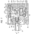
- a lever 21 is supported by a turning bracket 22 rotatably around an axis 23 in the arrow A direction and the opposite arrow A direction as well as it is mounted between a case 24 and a cover 25 rotatably around an axis portion 22a of the bracket 22 in the direction orthogonal to the arrow A direction (front and rear side direction with respect to the paper surface).
- a piece accommodating portion 26 is formed at the base end portion 21a of the lever 21, elongating in the axial direction such that a passing moderation piece 28 forced outward in the axial direction by a spring 27 comprising a compression spring is inserted in the piece accommodating portion 26 slidably in the arrow B direction and the opposite arrow B direction, that is, in the axial direction.
- operation projecting portions 29, projecting sideways, are formed at both side portions of the moderation piece 28 (only one of them is shown in FIG. 3).
- the operation projecting portions 29 are projected in the direction orthogonal to the axial direction, which is the moving direction of the moderation piece 28 (the arrow B direction and the opposite arrow B direction) and the rotational direction of the base end portion 21a of the lever 21 (the arrow A direction and the opposite arrow A direction).
- Holes 30 for guiding the movement of the operation projecting portions 29 are formed at the base end portion 21a of the lever 21, elongating in the axial direction.
- a passing cam surface 31 is formed in the bracket 22 at a portion facing with the base end portion 21a of the lever 21 such that the tip of the moderation piece 28 is contacted with the cam surface 31 slidably.
- the upper part of the cam surface 31 projects to the lever 21 side (left side) with respect to the lower part in FIG. 1.
- an accommodating portion 32 is formed in the upper part of FIG. 1, with a contact holder 33 comprising a movable member provided in the accommodating portion 32.
- the contact holder 33 is provided slidably in the arrow C direction and the opposite arrow C direction, that is, in the substantially the same direction as the moving direction of the moderation piece 28, and in the direction orthogonal thereto (front and rear side direction with respect to the paper surface).
- the contact holder 33 is provided with two arm portions 33a, with the base end portion 21a of the lever 21 interposed therebetween.
- Guiding portions 34 comprising inclined grooves inclined with respect to the moving direction of the contact holder 33 (the arrow C direction and the opposite arrow C direction) are formed on the inner surface side of the arm portions 33a.
- the operation projecting portions 29 are inserted in the guiding portions 34 slidably.
- a movable contact point 35 is provided on the upper part of the contact holder 33 in FIG. 1.
- the case 24 is provided with an insulator 36 so as to cover the contact holder 33, with a fixed contact point 37 to be contacted with or separated from the movable contact point 35 provided on the lower surface of the insulator 36.
- the movable contact point 35 and the fixed contact point 37 comprise a switch 38.
- an accommodating portion 40 is formed in the bracket 22 below the lever 21, with a turning moderation piece 42 forced outward in the axial direction by a spring 41 comprising a compression spring inserted slidably in the accommodating portion 40.
- a roller 43 is provided rotatably at the tip portion of the moderation piece 42.
- a turning moderation portion 44 is provided at a portion facing with the tip portion of the moderation piece 42, with the roller 43 contacting with the moderation portion 44 rotatably.
- the lever 21 when the lever 21 is rotated in the direction orthogonal to the arrow A direction (front and rear side direction with respect to the paper surface), the lever 21 is rotated with the bracket 22 around the axis portion 22a of the bracket 22. Then, the roller 43 of the turning moderation piece 42 rotates the moderation portion 44 as well as the base end portion 21a of the lever 21 presses the arm portions 33a of the contact holder 33 in the direction orthogonal to the arrow A direction so as to move the contact holder 33 in the same direction. Accordingly, the movable contact point 35 is contacted with the left or right fixed contact point (not illustrated) so that the turn switch is switched on.
- the operation projecting portions 29 for moving the contact holder 33 are provided in the moderation piece 28 for moving along the cam surface 31 according to the rotation of the lever 21, the moving amount of the moderation piece 28 in the axial direction (the arrow B direction) can be added to the moving stroke L2 of the contact holder 33 (see FIG. 1). Therefore, the moving stroke L2 of the contact holder 33 can be enlarged compared with the moving stroke L1 of the conventional contact holder 8 (L2>L1).
- the invention is not limited to the embodiment, but can be modified or expanded as follows.
- the embodiment has a configuration comprising the contact holder 33 having the movable contact point 35 as the movable member so that the state of the switch 38 is switched according to the movement of the movable contact 35 movable with the contact holder 33
- the movable member may comprise a tact switch to be operated independently according to the movement thereof.
- the operation projecting portions 29 may be displaced from the axial center line in the rotational direction in stead of being positioned on the axial center line of the base end portion 21a of the lever 21.
- the operation projecting portions for moving the movable member are provided in the moderation piece to be moved along the cam surface according to the rotation of the lever, the moving amount of the moderation piece can be added to the moving stroke of the movable member. Therefore, compared with the case with the operation projecting portions provided at the base end portion of the lever, the moving stroke of the movable member can be enlarged.
Landscapes
- Engineering & Computer Science (AREA)
- Mechanical Engineering (AREA)
- Switches With Compound Operations (AREA)
- Rotary Switch, Piano Key Switch, And Lever Switch (AREA)
- Mechanisms For Operating Contacts (AREA)
Applications Claiming Priority (2)
| Application Number | Priority Date | Filing Date | Title |
|---|---|---|---|
| JP32935198A JP3727790B2 (ja) | 1998-11-19 | 1998-11-19 | レバースイッチ装置 |
| JP32935198 | 1998-11-19 |
Publications (3)
| Publication Number | Publication Date |
|---|---|
| EP1003090A2 true EP1003090A2 (de) | 2000-05-24 |
| EP1003090A3 EP1003090A3 (de) | 2002-12-18 |
| EP1003090B1 EP1003090B1 (de) | 2007-01-17 |
Family
ID=18220495
Family Applications (1)
| Application Number | Title | Priority Date | Filing Date |
|---|---|---|---|
| EP99122788A Expired - Lifetime EP1003090B1 (de) | 1998-11-19 | 1999-11-16 | Hebelschaltervorrichtung |
Country Status (4)
| Country | Link |
|---|---|
| US (1) | US6268575B1 (de) |
| EP (1) | EP1003090B1 (de) |
| JP (1) | JP3727790B2 (de) |
| DE (1) | DE69934860T2 (de) |
Families Citing this family (3)
| Publication number | Priority date | Publication date | Assignee | Title |
|---|---|---|---|---|
| US20080121500A1 (en) * | 2006-11-24 | 2008-05-29 | Kabushiki Kaisha Tokai Rika Denki Seisakusho | Vehicular lever switch apparatus |
| KR20090061369A (ko) * | 2007-12-11 | 2009-06-16 | 현대자동차주식회사 | 시프트 레버 세트를 구비한 자동차 |
| JP7269758B2 (ja) * | 2019-03-07 | 2023-05-09 | 東洋電装株式会社 | レバースイッチ |
Family Cites Families (10)
| Publication number | Priority date | Publication date | Assignee | Title |
|---|---|---|---|---|
| DE1136876B (de) * | 1958-03-14 | 1962-09-20 | Mors Electricite | Geber fuer mechanische Fernsteuerungs-Vorrichtungen |
| US3167622A (en) * | 1962-08-24 | 1965-01-26 | Zinsco Electrical Products | Roller actuated snap action electric toggle switch |
| DE3717251C2 (de) * | 1987-05-22 | 2001-10-04 | Teves Gmbh Alfred | Elektrischer Schalter, insbesondere Lenkstockschalter für Kraftfahrzeuge |
| DE3829109C2 (de) * | 1988-08-27 | 1998-02-26 | Teves Gmbh Alfred | Elektrischer Schalter, insbesondere Lenkstockschalter für Kraftfahrzeuge |
| JPH08253073A (ja) * | 1995-03-20 | 1996-10-01 | Honda Motor Co Ltd | 非常点滅灯装置 |
| JP3888713B2 (ja) * | 1996-09-26 | 2007-03-07 | ナイルス株式会社 | レバースイッチ装置 |
| JPH10172389A (ja) * | 1996-12-11 | 1998-06-26 | Niles Parts Co Ltd | レバースイッチ装置 |
| JPH10172388A (ja) * | 1996-12-11 | 1998-06-26 | Niles Parts Co Ltd | 車両用レバースイッチの構造 |
| JPH1125807A (ja) * | 1997-06-30 | 1999-01-29 | Niles Parts Co Ltd | 車両用レバースイッチの構造 |
| US6140597A (en) * | 1997-09-04 | 2000-10-31 | Harness System Technologies Research, Ltd. | Breaker device having an incomplete-connection prevention function |
-
1998
- 1998-11-19 JP JP32935198A patent/JP3727790B2/ja not_active Expired - Fee Related
-
1999
- 1999-11-12 US US09/432,571 patent/US6268575B1/en not_active Expired - Lifetime
- 1999-11-16 EP EP99122788A patent/EP1003090B1/de not_active Expired - Lifetime
- 1999-11-16 DE DE69934860T patent/DE69934860T2/de not_active Expired - Lifetime
Non-Patent Citations (1)
| Title |
|---|
| None |
Also Published As
| Publication number | Publication date |
|---|---|
| US6268575B1 (en) | 2001-07-31 |
| JP3727790B2 (ja) | 2005-12-14 |
| DE69934860D1 (de) | 2007-03-08 |
| EP1003090A3 (de) | 2002-12-18 |
| JP2000156128A (ja) | 2000-06-06 |
| EP1003090B1 (de) | 2007-01-17 |
| DE69934860T2 (de) | 2007-05-24 |
Similar Documents
| Publication | Publication Date | Title |
|---|---|---|
| US5672855A (en) | Canceling mechanism for a vehicular turn signal switch | |
| JPH056599U (ja) | レバースイツチ装置 | |
| US6268575B1 (en) | Lever switch device | |
| US4739127A (en) | Snap switch | |
| US5200584A (en) | Lever switch | |
| US20080121500A1 (en) | Vehicular lever switch apparatus | |
| US6660951B2 (en) | Canceling structure of combination switch | |
| JP2596766Y2 (ja) | スイッチ装置 | |
| CN217305825U (zh) | 一种可切换滚轮模式的鼠标改良结构 | |
| KR100584946B1 (ko) | 레버 스위치 장치 | |
| JP2002343196A (ja) | スイッチ装置 | |
| JPS6021872Y2 (ja) | スライド式スイツチ | |
| US20080121505A1 (en) | Switch apparatus | |
| CN218447688U (zh) | 面板开关 | |
| JP2605918Y2 (ja) | スイッチ装置 | |
| JP4397677B2 (ja) | 電動工具用スイッチ | |
| JPH0733326Y2 (ja) | スイッチ装置 | |
| JP2575079Y2 (ja) | 車両用レバースイッチの構造 | |
| KR100583877B1 (ko) | 미러 스위치 장치 | |
| JP2602947Y2 (ja) | スイッチ装置 | |
| JP2001076591A (ja) | シーソ型スイッチ装置 | |
| JP3113496B2 (ja) | 速動式スイッチ装置 | |
| JP3682540B2 (ja) | プリンター用操作盤傾斜装置 | |
| JPH081538Y2 (ja) | 複合スイッチ装置 | |
| JPH0597031U (ja) | スイッチ装置 |
Legal Events
| Date | Code | Title | Description |
|---|---|---|---|
| PUAI | Public reference made under article 153(3) epc to a published international application that has entered the european phase |
Free format text: ORIGINAL CODE: 0009012 |
|
| AK | Designated contracting states |
Kind code of ref document: A2 Designated state(s): AT BE CH CY DE DK ES FI FR GB GR IE IT LI LU MC NL PT SE |
|
| AX | Request for extension of the european patent |
Free format text: AL;LT;LV;MK;RO;SI |
|
| PUAL | Search report despatched |
Free format text: ORIGINAL CODE: 0009013 |
|
| AK | Designated contracting states |
Kind code of ref document: A3 Designated state(s): AT BE CH CY DE DK ES FI FR GB GR IE IT LI LU MC NL PT SE |
|
| AX | Request for extension of the european patent |
Free format text: AL;LT;LV;MK;RO;SI |
|
| 17P | Request for examination filed |
Effective date: 20021213 |
|
| AKX | Designation fees paid |
Designated state(s): DE FR GB SE |
|
| GRAP | Despatch of communication of intention to grant a patent |
Free format text: ORIGINAL CODE: EPIDOSNIGR1 |
|
| GRAS | Grant fee paid |
Free format text: ORIGINAL CODE: EPIDOSNIGR3 |
|
| GRAA | (expected) grant |
Free format text: ORIGINAL CODE: 0009210 |
|
| AK | Designated contracting states |
Kind code of ref document: B1 Designated state(s): DE FR GB SE |
|
| REG | Reference to a national code |
Ref country code: GB Ref legal event code: FG4D |
|
| REF | Corresponds to: |
Ref document number: 69934860 Country of ref document: DE Date of ref document: 20070308 Kind code of ref document: P |
|
| REG | Reference to a national code |
Ref country code: SE Ref legal event code: TRGR |
|
| ET | Fr: translation filed | ||
| PLBE | No opposition filed within time limit |
Free format text: ORIGINAL CODE: 0009261 |
|
| STAA | Information on the status of an ep patent application or granted ep patent |
Free format text: STATUS: NO OPPOSITION FILED WITHIN TIME LIMIT |
|
| 26N | No opposition filed |
Effective date: 20071018 |
|
| PGFP | Annual fee paid to national office [announced via postgrant information from national office to epo] |
Ref country code: FR Payment date: 20101123 Year of fee payment: 12 |
|
| PGFP | Annual fee paid to national office [announced via postgrant information from national office to epo] |
Ref country code: DE Payment date: 20101110 Year of fee payment: 12 |
|
| PGFP | Annual fee paid to national office [announced via postgrant information from national office to epo] |
Ref country code: SE Payment date: 20101111 Year of fee payment: 12 Ref country code: GB Payment date: 20101110 Year of fee payment: 12 |
|
| REG | Reference to a national code |
Ref country code: SE Ref legal event code: EUG |
|
| GBPC | Gb: european patent ceased through non-payment of renewal fee |
Effective date: 20111116 |
|
| REG | Reference to a national code |
Ref country code: FR Ref legal event code: ST Effective date: 20120731 |
|
| REG | Reference to a national code |
Ref country code: DE Ref legal event code: R119 Ref document number: 69934860 Country of ref document: DE Effective date: 20120601 |
|
| PG25 | Lapsed in a contracting state [announced via postgrant information from national office to epo] |
Ref country code: SE Free format text: LAPSE BECAUSE OF NON-PAYMENT OF DUE FEES Effective date: 20111117 Ref country code: GB Free format text: LAPSE BECAUSE OF NON-PAYMENT OF DUE FEES Effective date: 20111116 |
|
| PG25 | Lapsed in a contracting state [announced via postgrant information from national office to epo] |
Ref country code: FR Free format text: LAPSE BECAUSE OF NON-PAYMENT OF DUE FEES Effective date: 20111130 |
|
| PG25 | Lapsed in a contracting state [announced via postgrant information from national office to epo] |
Ref country code: DE Free format text: LAPSE BECAUSE OF NON-PAYMENT OF DUE FEES Effective date: 20120601 |