EP1003091A2 - Système d'interface - Google Patents
Système d'interface Download PDFInfo
- Publication number
- EP1003091A2 EP1003091A2 EP99122960A EP99122960A EP1003091A2 EP 1003091 A2 EP1003091 A2 EP 1003091A2 EP 99122960 A EP99122960 A EP 99122960A EP 99122960 A EP99122960 A EP 99122960A EP 1003091 A2 EP1003091 A2 EP 1003091A2
- Authority
- EP
- European Patent Office
- Prior art keywords
- status
- computer
- status information
- information
- stencil printer
- Prior art date
- Legal status (The legal status is an assumption and is not a legal conclusion. Google has not performed a legal analysis and makes no representation as to the accuracy of the status listed.)
- Withdrawn
Links
Images



Classifications
-
- G—PHYSICS
- G06—COMPUTING OR CALCULATING; COUNTING
- G06F—ELECTRIC DIGITAL DATA PROCESSING
- G06F3/00—Input arrangements for transferring data to be processed into a form capable of being handled by the computer; Output arrangements for transferring data from processing unit to output unit, e.g. interface arrangements
- G06F3/12—Digital output to print unit, e.g. line printer, chain printer
- G06F3/1201—Dedicated interfaces to print systems
- G06F3/1202—Dedicated interfaces to print systems specifically adapted to achieve a particular effect
- G06F3/1203—Improving or facilitating administration, e.g. print management
- G06F3/1207—Improving or facilitating administration, e.g. print management resulting in the user being informed about print result after a job submission
-
- G—PHYSICS
- G06—COMPUTING OR CALCULATING; COUNTING
- G06F—ELECTRIC DIGITAL DATA PROCESSING
- G06F3/00—Input arrangements for transferring data to be processed into a form capable of being handled by the computer; Output arrangements for transferring data from processing unit to output unit, e.g. interface arrangements
- G06F3/12—Digital output to print unit, e.g. line printer, chain printer
- G06F3/1201—Dedicated interfaces to print systems
- G06F3/1223—Dedicated interfaces to print systems specifically adapted to use a particular technique
- G06F3/1229—Printer resources management or printer maintenance, e.g. device status, power levels
-
- G—PHYSICS
- G06—COMPUTING OR CALCULATING; COUNTING
- G06F—ELECTRIC DIGITAL DATA PROCESSING
- G06F3/00—Input arrangements for transferring data to be processed into a form capable of being handled by the computer; Output arrangements for transferring data from processing unit to output unit, e.g. interface arrangements
- G06F3/12—Digital output to print unit, e.g. line printer, chain printer
- G06F3/1201—Dedicated interfaces to print systems
- G06F3/1223—Dedicated interfaces to print systems specifically adapted to use a particular technique
- G06F3/1237—Print job management
- G06F3/1259—Print job monitoring, e.g. job status
-
- G—PHYSICS
- G06—COMPUTING OR CALCULATING; COUNTING
- G06F—ELECTRIC DIGITAL DATA PROCESSING
- G06F3/00—Input arrangements for transferring data to be processed into a form capable of being handled by the computer; Output arrangements for transferring data from processing unit to output unit, e.g. interface arrangements
- G06F3/12—Digital output to print unit, e.g. line printer, chain printer
- G06F3/1201—Dedicated interfaces to print systems
- G06F3/1278—Dedicated interfaces to print systems specifically adapted to adopt a particular infrastructure
- G06F3/1284—Local printer device
Definitions
- This invention relates to an interface system for watching the status of a stencil printer when printing data generated by a computer is output to the stencil printer.
- a stencil printer is sometimes connected to a computer by way of an interface system to print on request from the computer.
- a printer driver installed in the computer there has been known one which has function of watching the status of the stencil printer.
- the interface system analyzes the printing data and converts the data to raster data.
- the interface system outputs the raster data as page data and the stencil printer prints on the basis of the page data.
- the interface system is provided with a status control means which sets instruction on the action of the stencil printer on request from the computer.
- the interface system takes information on whether the stencil printer is in a stopped state, in action, or in an error state as status information through the status control means and stores the information in an updated status memory means.
- the interface system sends the updated status of the stencil printer on request from the computer.
- the printer driver of the computer outputs request to switch the direction of data transfer to the interface system when the status information becomes necessary during transfer of the printing data, and the interface system sends the updated status information in a predetermined data length to the computer upon receipt of the request.
- the printer driver During receiving the status information, the printer driver transfers and receives the status information in a fixed format wherein it outputs request to switch the direction of data transfer to the printing data transfer direction after it receives the predetermined data length. Further there has been known a variable format wherein the printer driver watches the time interval between adjacent series of data (time-out period) at a breakpoint of status information from the interface system, recalculates the time- out period each time it receives a series of data, and outputs request to switch the direction of data transfer to the printing data transfer direction after the time-out period lapses.
- the compatibility mode As the standard of data transmission between the computer and the printer, there have been known a compatibility mode, a nibble mode, a byte mode, an ECP mode and an EPP mode.
- the compatibility mode is generally used in the case of one-way communication which is a conventional system.
- the nibble mode is employed as a basic system. That is, when normal printing data are send to the printer from the computer, the printing data is transferred in the compatibility mode and when the computer requires status information on the printer, the status information is transferred from the printer to the computer in the nibble mode. Accordingly, during printing, the printing data and the status information are alternately transferred at predetermined intervals.
- the primary object of the present invention is to provide an interface system which can efficiently transfer the status information.
- an interface system which transmits printing data from a computer to a stencil printer and transmits status information on the stencil printer to the computer, characterized by having
- status information means information on whether the stencil printer is in a stopped state, in action, or in an error state.
- the interface system of the present invention be provided with a means for transmitting the updated status information in place of the status difference information when so requested by the computer.
- the status difference information generation means be provided with a means which separates the updated status information into fixed status information which represents the fixed status of the stencil printer and variable status information which represents the variable status of the stencil printer, and generates the status difference information on the basis of the variable status information.
- the status difference information which represents difference of the updated status information from the previously transmitted status information is transmitted to the computer
- the amount of data to be transmitted is minimized and the status information on the stencil printer can be efficiently transmitted to the computer. Accordingly, even in the case where the amount of printing data is large as in a host base printer driver, the status of the stencil printer can be watched without deteriorating data transmission efficiency.
- the status information is transmitted to the computer from the interface system interrupting transfer of the printing data from the computer to the interface in a nibble mode of IEEE 1284, where data are transmitted 4 bits by 4bits
- the status information can be more efficiently transmitted by reducing the amount of data in the manner described above.
- data traffic can be reduced and data transfer efficiency is improved by reducing the amount of data of status information.
- the interface system of the present invention When the interface system of the present invention is provided with a means for transmitting the updated status information in place of the status difference information when so requested by the computer, the whole updated status information can be transmitted to the computer in situations where the previously transmitted status information has been lost from the computer, e.g., by disconnecting the computer from the power source or a different computer is connected to the interface system.
- the communication load between the interface system and the stencil printer can be lightened, whereby the status information can be transferred more efficiently.
- a printing system comprises a stencil printer 1, which is composed of a stencil making section and a stencil printing section, a computer 2 which outputs printing instructions to the stencil printer 1 and watches the status of the stencil printer, and an interface system 3 in accordance with an embodiment of the present invention.
- a second computer 4 is connected to the interface system 3 through a pair of modems 5 and 6 and a telephone line, and third and fourth computers 7 and 8 are connected to the interface system through a LAN.
- Exchange of data between the second computer 4 and the interface system 3 and that between the third and fourth computers 7 and 8 and the interface system 3 are the same as that between the first computer 2 and the interface system 3. Accordingly exchange of data between the first computer 2 and the interface system 3 will be only described, hereinbelow.
- the interface system 3 comprises a CPU 10 which controls the interface system 3, and a ROM 11, a RAM 12, an input/output means 13, a status control means 14 and a video data control means 15 which are connected to the CPU 10.
- the status control means 14 controls the status of the stencil printer 1
- the video data control means 15 controls video data generated by printing data.
- the interface system 3 switches the direction of data transfer when the computer 2 requests the status information on the stencil printer 1 during transmission of printing data from the computer 2 and transmits the status information from the stencil printer 1 to the computer 2.
- the ROM 11 stores therein programs having various functions for controlling the interface system 3. Specifically, there stored in the ROM 11 programs for executing functions of controlling input of printing data into the stencil printer 1, controlling output of the status information from the interface system 3 to the computer 2, updating the structure of the status information transmitted from the stencil printer 1, controlling input of the status information from the stencil printer 1 to the interface system 3, analyzing the printing data from the computer 2 to obtain raster data, and controlling output of video data to the stencil printer 1.
- the RAM 12 temporarily stores data transmitted to the interface system 3 or data to be transmitted to the stencil printer 1 or the computer 2. Specifically, the RAM 12 stores the printing data to be transmitted from the computer 2 to the stencil printer 1, the raster data obtained by analyzing the printing data, the updated status information, the previously transmitted status information which has been previously transmitted to the computer 2, the status difference information which represents a difference of the updated status information from the previously transmitted status information and are obtained in the manner to be described later, and the like.
- the input/output means 13 is for exchanging data with the external systems. Specifically, the input/output means 13 receives the printing data and the status information from the computer 2 as well as request for refresh status (to be described later), and outputs the status information to the computer 2.
- the status control means 14 sets instructions on the action of the stencil printer 1 and takes in the status information on the status of the stencil printer 1, that is, whether the stencil printer 1 is in a stopped state, in action, or in an error state.
- the video data control means 15 outputs the raster data in the RAM 12 to the stencil printer 1.
- the status of the stencil printer 1 comprises fixed status which is not varied with progress of printing or lapse of time (e.g., status of video clock of the stencil printer 1, status of version of the stencil printer 1 and the like) and variable status such as the number of remainder copies, the printing speed and the size of the printing papers.
- the contents of the status are distinguished by an ID number.
- the fixed status information does not change after it is once transmitted to the computer 2.
- the updated status information transmitted from the stencil printer 1 is separated into fixed status information and variable status information, and status difference information is generated on the basis of only the variable status information. That is, the status difference information is obtained by collecting only variable status information which represents status of the stencil printer 1 different from the status represented by the previously transmitted status information corresponding thereto, and then is transmitted to the computer 2.
- FIG 4 shows forms of request command to the stencil printer 1 and response status from the same.
- request command "CH” represents a command header (the start of the command packet)
- CE represents the end of command (the end of the command packet)
- content of request represents the contents of request such as those shown in Figure 5.
- 0x01 means that the basic status is requested
- 0x02 means that the number of copies to be printed is requested
- 0x03 means that the resolution is requested.
- SH represents a status header (the start of the status packet)
- SE represents the end of status (the end of the status packet). For example, for a request "0x02", the upper byte and the lower byte of the response status on the number of copies to be printed are taken and recorded in the updated status information at ID numbers 3 and 4.
- the interface system 3 transmits various request packets to the stencil printer 1 in order to obtain various kinds of status information.
- the stencil printer 1 analyzes the request packets and transmits response status packets in response to the request packets to the interface system 3.
- the interface system 3 repeatedly makes request at predetermined intervals and stores the status information at the respective times in the RAM 12 in sequence.
- the interface system 3 reads out the updated status information, determines the status difference information and transmits the status difference information to the computer 2 on request from the computer 2.
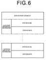
- the status difference information comprises a status post counter and n , pieces of status information.
- k -th ( k stands for 1 to n ) status information includes the status ID number for the status information and the status data.
- the status post counter is attached only to the first status difference information and represents the status ID numbers and the number of pieces of the status data ( n in this particular example) in the status difference information to be transmitted.
- the status ID numbers are those in the updated status information shown in Figure 3 and the status data represents the actual content of the status which has changed. For example, when only the lower byte for the number of remainder copies changes from 8 to 7, the status difference information becomes the following 3-byte data.
- step S4 determines whether the power signal of the stencil printer 1 is on.
- steps S1 to S4 are repeated until the power signal is turned on.
- step S5 When it is determined in step S5 that the fixed status request flag is "True”, the interface system 3 takes in the fixed status of the stencil printer 1 and stores the fixed status in the RAM 12 as updated status information (step S6) and sets the fixed status request flag to "False” (step S7). Then the interface system 3 takes in variable status and stores the variable status in the RAM 12 as updated status information.
- step S8 On the other hand, when it is determined in step S5 that the fixed status request flag is "False”, the interface system 3 directly executes step S8 after step 5 and the interface system 3 takes in variable status and stores the variable status in the RAM 12 as updated status information. (step S8) Then the interface system 3 determines in step S9 whether the computer 2 is making a request for the status information. When it is determined in step S9 that the computer 2 is not making a request for the status information, the interface system 3 repeats steps S4 to S9 until the computer 2 comes to make the request.
- step S10 determines in step S10 whether the computer 2 is making a request for refresh status information.
- the interface system 3 extracts only the variable status from the status information transmitted from the stencil printer 1 as updated status information and generates status difference information as the difference of the variable status of the updated status information from the previously transmitted status information which has been previously transmitted to the computer 2.
- step S12 When it is determined in step S10 that the computer 2 is making a request for refresh status information, the interface system 3 first clears previously transmitted status information stored in the RAM 12 (step S11) and then executes step S12.
- the status difference information generated by the interface system 3 becomes equal to the updated status information as transmitted from the stencil printer 1.
- the interface system 3 transmits the status difference information thus obtained to the computer 2.
- the interface system 3 updates the previously transmitted status information according to the status difference information in step S14 and then returns to step S4.
- the interface system 3 repeats steps S4 to S14 until the computer 2 stops watching the status of the stencil printer 1.
- the interface system 3 stops transmission of the status information.
- the printing system of this embodiment since only the status difference information which represents difference of the updated status information from the previously transmitted status information is transmitted to the computer 2, the amount of data to be transmitted is minimized and the status information on the stencil printer 1 can be efficiently transmitted to the computer 2.
- the updated status information transmitted from the stencil printer 1 is separated into fixed status information and variable status information, and status difference information is generated on the basis of only the variable status information, the status difference information may be generated without separating the updated status information into fixed and variable status information.
Landscapes
- Engineering & Computer Science (AREA)
- Theoretical Computer Science (AREA)
- Human Computer Interaction (AREA)
- Physics & Mathematics (AREA)
- General Engineering & Computer Science (AREA)
- General Physics & Mathematics (AREA)
- Accessory Devices And Overall Control Thereof (AREA)
- Debugging And Monitoring (AREA)
- Communication Control (AREA)
Applications Claiming Priority (2)
| Application Number | Priority Date | Filing Date | Title |
|---|---|---|---|
| JP32804198A JP3537332B2 (ja) | 1998-11-18 | 1998-11-18 | インターフェース装置 |
| JP32804198 | 1998-11-18 |
Publications (2)
| Publication Number | Publication Date |
|---|---|
| EP1003091A2 true EP1003091A2 (fr) | 2000-05-24 |
| EP1003091A3 EP1003091A3 (fr) | 2003-12-17 |
Family
ID=18205862
Family Applications (1)
| Application Number | Title | Priority Date | Filing Date |
|---|---|---|---|
| EP99122960A Withdrawn EP1003091A3 (fr) | 1998-11-18 | 1999-11-18 | Système d'interface |
Country Status (3)
| Country | Link |
|---|---|
| US (1) | US6196735B1 (fr) |
| EP (1) | EP1003091A3 (fr) |
| JP (1) | JP3537332B2 (fr) |
Cited By (1)
| Publication number | Priority date | Publication date | Assignee | Title |
|---|---|---|---|---|
| EP1691269A1 (fr) * | 2005-02-09 | 2006-08-16 | Deutsche Post AG | Système d'impression |
Families Citing this family (17)
| Publication number | Priority date | Publication date | Assignee | Title |
|---|---|---|---|---|
| JP4565706B2 (ja) * | 2000-06-12 | 2010-10-20 | 東北リコー株式会社 | 孔版印刷機及び印刷システム |
| US7117239B1 (en) | 2000-07-28 | 2006-10-03 | Axeda Corporation | Reporting the state of an apparatus to a remote computer |
| US7185014B1 (en) * | 2000-09-22 | 2007-02-27 | Axeda Corporation | Retrieving data from a server |
| US8108543B2 (en) | 2000-09-22 | 2012-01-31 | Axeda Corporation | Retrieving data from a server |
| US7149792B1 (en) | 2000-11-20 | 2006-12-12 | Axeda Corporation | Device registration mechanism |
| US7254601B2 (en) | 2001-12-20 | 2007-08-07 | Questra Corporation | Method and apparatus for managing intelligent assets in a distributed environment |
| US7178149B2 (en) | 2002-04-17 | 2007-02-13 | Axeda Corporation | XML scripting of soap commands |
| US7966418B2 (en) | 2003-02-21 | 2011-06-21 | Axeda Corporation | Establishing a virtual tunnel between two computer programs |
| JP2005157521A (ja) * | 2003-11-21 | 2005-06-16 | Hitachi Ltd | 遠隔記憶装置の状態情報監視方法および記憶サブシステム |
| JP4421385B2 (ja) | 2004-06-09 | 2010-02-24 | 株式会社日立製作所 | 計算機システム |
| US8370479B2 (en) * | 2006-10-03 | 2013-02-05 | Axeda Acquisition Corporation | System and method for dynamically grouping devices based on present device conditions |
| US8065397B2 (en) * | 2006-12-26 | 2011-11-22 | Axeda Acquisition Corporation | Managing configurations of distributed devices |
| JP4930051B2 (ja) * | 2006-12-28 | 2012-05-09 | ブラザー工業株式会社 | ステータスモニタプログラム |
| JP4693803B2 (ja) | 2007-03-12 | 2011-06-01 | コニカミノルタビジネステクノロジーズ株式会社 | Httpサーバ及びプログラム |
| US8478861B2 (en) | 2007-07-06 | 2013-07-02 | Axeda Acquisition Corp. | Managing distributed devices with limited connectivity |
| JP4967913B2 (ja) * | 2007-08-06 | 2012-07-04 | ブラザー工業株式会社 | 通信システムと通信装置 |
| JP5283477B2 (ja) | 2008-10-23 | 2013-09-04 | アトムメディカル株式会社 | 保育器 |
Citations (1)
| Publication number | Priority date | Publication date | Assignee | Title |
|---|---|---|---|---|
| EP0654757A2 (fr) * | 1993-11-16 | 1995-05-24 | Seiko Epson Corporation | Appareil d'impression et méthode pour son contrôle |
Family Cites Families (6)
| Publication number | Priority date | Publication date | Assignee | Title |
|---|---|---|---|---|
| US5214772A (en) * | 1989-12-13 | 1993-05-25 | Joseph Weinberger | System for automatically monitoring copiers from a remote location |
| JP3238817B2 (ja) * | 1993-12-28 | 2001-12-17 | キヤノン株式会社 | 画像形成装置の管理装置および画像形成装置 |
| US5502543A (en) * | 1994-06-28 | 1996-03-26 | Xerox Corporation | System for collecting statistical data on remotely monitored machines |
| CN100381941C (zh) * | 1995-02-22 | 2008-04-16 | 佳能株式会社 | 图象形成设备、图象形成系统以及向图象形成装置输出图象信息的设备 |
| US5798738A (en) * | 1995-03-25 | 1998-08-25 | Ricoh Company, Ltd. | Printing manager system for a copier in a network |
| JPH1063444A (ja) * | 1996-08-27 | 1998-03-06 | Riso Kagaku Corp | 画像形成装置用コンピュータインターフェイス装置 |
-
1998
- 1998-11-18 JP JP32804198A patent/JP3537332B2/ja not_active Expired - Lifetime
-
1999
- 1999-11-17 US US09/441,668 patent/US6196735B1/en not_active Expired - Lifetime
- 1999-11-18 EP EP99122960A patent/EP1003091A3/fr not_active Withdrawn
Patent Citations (1)
| Publication number | Priority date | Publication date | Assignee | Title |
|---|---|---|---|---|
| EP0654757A2 (fr) * | 1993-11-16 | 1995-05-24 | Seiko Epson Corporation | Appareil d'impression et méthode pour son contrôle |
Cited By (2)
| Publication number | Priority date | Publication date | Assignee | Title |
|---|---|---|---|---|
| EP1691269A1 (fr) * | 2005-02-09 | 2006-08-16 | Deutsche Post AG | Système d'impression |
| WO2006084533A1 (fr) * | 2005-02-09 | 2006-08-17 | Deutsche Post Ag | Systeme d'impression |
Also Published As
| Publication number | Publication date |
|---|---|
| JP2000148416A (ja) | 2000-05-30 |
| JP3537332B2 (ja) | 2004-06-14 |
| EP1003091A3 (fr) | 2003-12-17 |
| US6196735B1 (en) | 2001-03-06 |
Similar Documents
| Publication | Publication Date | Title |
|---|---|---|
| EP1003091A2 (fr) | Système d'interface | |
| US8037131B2 (en) | Data transfer utilizing preview data | |
| US6321266B1 (en) | Input/output apparatus connected to a plurality of host computers via a network | |
| US6970263B2 (en) | Print system, printing method, and server | |
| US5933851A (en) | Time-stamp and hash-based file modification monitor with multi-user notification and method thereof | |
| US8384972B2 (en) | Image input/output control apparatus, image processing apparatus, image processing method, data communication apparatus, and data communication method | |
| US5175762A (en) | Remote printing using FAX | |
| EP0483984B1 (fr) | Transfert Ascii à Ascii en utilisant un protocole de facsimile | |
| US7230733B2 (en) | Communication control method of internet facsimile and internet facsimile | |
| JP2001080141A (ja) | 印刷制御装置及び方法、プリンタ装置及び印刷方法、印刷システム及び印刷方法 | |
| JPH11275299A (ja) | 画像読取装置及び画像読取装置における動作指示通知方法 | |
| DE69125451T2 (de) | Ferndrucker mit Fax | |
| JP2833512B2 (ja) | ファクシミリ装置 | |
| JP2658931B2 (ja) | プリンタコントローラ | |
| JP2844775B2 (ja) | ファクシミリ装置 | |
| JP4135439B2 (ja) | 画像処理システム、画像処理装置、画像処理方法、プログラム、記憶媒体 | |
| JPH09261377A (ja) | ファクシミリ端末 | |
| JPH1139117A (ja) | プリンタ制御装置 | |
| JP3527049B2 (ja) | ファクシミリ装置 | |
| JP2518818B2 (ja) | 通信制御装置 | |
| JPH0667825A (ja) | 遠隔印刷システム | |
| JPH07177352A (ja) | プリンタ | |
| JPH10240655A (ja) | インタフェース装置 | |
| JPH05301383A (ja) | カラー・プリンタ及びカラー印刷システム | |
| JPH02308662A (ja) | データ通信方式および送受信装置 |
Legal Events
| Date | Code | Title | Description |
|---|---|---|---|
| PUAI | Public reference made under article 153(3) epc to a published international application that has entered the european phase |
Free format text: ORIGINAL CODE: 0009012 |
|
| 17P | Request for examination filed |
Effective date: 19991118 |
|
| AK | Designated contracting states |
Kind code of ref document: A2 Designated state(s): AT BE CH CY DE DK ES FI FR GB GR IE IT LI LU MC NL PT SE |
|
| AX | Request for extension of the european patent |
Free format text: AL;LT;LV;MK;RO;SI |
|
| PUAL | Search report despatched |
Free format text: ORIGINAL CODE: 0009013 |
|
| AK | Designated contracting states |
Kind code of ref document: A3 Designated state(s): AT BE CH CY DE DK ES FI FR GB GR IE IT LI LU MC NL PT SE |
|
| AX | Request for extension of the european patent |
Extension state: AL LT LV MK RO SI |
|
| AKX | Designation fees paid |
Designated state(s): DE FR GB |
|
| 17Q | First examination report despatched |
Effective date: 20071112 |
|
| STAA | Information on the status of an ep patent application or granted ep patent |
Free format text: STATUS: THE APPLICATION IS DEEMED TO BE WITHDRAWN |
|
| 18D | Application deemed to be withdrawn |
Effective date: 20091127 |