EP1003163A1 - Optischer aufzeichnungsträger - Google Patents
Optischer aufzeichnungsträger Download PDFInfo
- Publication number
- EP1003163A1 EP1003163A1 EP99923917A EP99923917A EP1003163A1 EP 1003163 A1 EP1003163 A1 EP 1003163A1 EP 99923917 A EP99923917 A EP 99923917A EP 99923917 A EP99923917 A EP 99923917A EP 1003163 A1 EP1003163 A1 EP 1003163A1
- Authority
- EP
- European Patent Office
- Prior art keywords
- groove
- grooves
- track
- laser beam
- recording
- Prior art date
- Legal status (The legal status is an assumption and is not a legal conclusion. Google has not performed a legal analysis and makes no representation as to the accuracy of the status listed.)
- Withdrawn
Links
Images






Classifications
-
- G—PHYSICS
- G11—INFORMATION STORAGE
- G11B—INFORMATION STORAGE BASED ON RELATIVE MOVEMENT BETWEEN RECORD CARRIER AND TRANSDUCER
- G11B11/00—Recording on or reproducing from the same record carrier wherein for these two operations the methods are covered by different main groups of groups G11B3/00 - G11B7/00 or by different subgroups of group G11B9/00; Record carriers therefor
- G11B11/10—Recording on or reproducing from the same record carrier wherein for these two operations the methods are covered by different main groups of groups G11B3/00 - G11B7/00 or by different subgroups of group G11B9/00; Record carriers therefor using recording by magnetic means or other means for magnetisation or demagnetisation of a record carrier, e.g. light induced spin magnetisation; Demagnetisation by thermal or stress means in the presence or not of an orienting magnetic field
- G11B11/105—Recording on or reproducing from the same record carrier wherein for these two operations the methods are covered by different main groups of groups G11B3/00 - G11B7/00 or by different subgroups of group G11B9/00; Record carriers therefor using recording by magnetic means or other means for magnetisation or demagnetisation of a record carrier, e.g. light induced spin magnetisation; Demagnetisation by thermal or stress means in the presence or not of an orienting magnetic field using a beam of light or a magnetic field for recording by change of magnetisation and a beam of light for reproducing, i.e. magneto-optical, e.g. light-induced thermomagnetic recording, spin magnetisation recording, Kerr or Faraday effect reproducing
- G11B11/1055—Disposition or mounting of transducers relative to record carriers
- G11B11/10556—Disposition or mounting of transducers relative to record carriers with provision for moving or switching or masking the transducers in or out of their operative position
- G11B11/10563—Access of indexed parts
- G11B11/10565—Marks for track change, e.g. prepits, gray codes
-
- G—PHYSICS
- G11—INFORMATION STORAGE
- G11B—INFORMATION STORAGE BASED ON RELATIVE MOVEMENT BETWEEN RECORD CARRIER AND TRANSDUCER
- G11B11/00—Recording on or reproducing from the same record carrier wherein for these two operations the methods are covered by different main groups of groups G11B3/00 - G11B7/00 or by different subgroups of group G11B9/00; Record carriers therefor
- G11B11/10—Recording on or reproducing from the same record carrier wherein for these two operations the methods are covered by different main groups of groups G11B3/00 - G11B7/00 or by different subgroups of group G11B9/00; Record carriers therefor using recording by magnetic means or other means for magnetisation or demagnetisation of a record carrier, e.g. light induced spin magnetisation; Demagnetisation by thermal or stress means in the presence or not of an orienting magnetic field
- G11B11/105—Recording on or reproducing from the same record carrier wherein for these two operations the methods are covered by different main groups of groups G11B3/00 - G11B7/00 or by different subgroups of group G11B9/00; Record carriers therefor using recording by magnetic means or other means for magnetisation or demagnetisation of a record carrier, e.g. light induced spin magnetisation; Demagnetisation by thermal or stress means in the presence or not of an orienting magnetic field using a beam of light or a magnetic field for recording by change of magnetisation and a beam of light for reproducing, i.e. magneto-optical, e.g. light-induced thermomagnetic recording, spin magnetisation recording, Kerr or Faraday effect reproducing
- G11B11/1055—Disposition or mounting of transducers relative to record carriers
- G11B11/10556—Disposition or mounting of transducers relative to record carriers with provision for moving or switching or masking the transducers in or out of their operative position
- G11B11/10563—Access of indexed parts
-
- G—PHYSICS
- G11—INFORMATION STORAGE
- G11B—INFORMATION STORAGE BASED ON RELATIVE MOVEMENT BETWEEN RECORD CARRIER AND TRANSDUCER
- G11B7/00—Recording or reproducing by optical means, e.g. recording using a thermal beam of optical radiation by modifying optical properties or the physical structure, reproducing using an optical beam at lower power by sensing optical properties; Record carriers therefor
- G11B7/007—Arrangement of the information on the record carrier, e.g. form of tracks, actual track shape, e.g. wobbled, or cross-section, e.g. v-shaped; Sequential information structures, e.g. sectoring or header formats within a track
- G11B7/00718—Groove and land recording, i.e. user data recorded both in the grooves and on the lands
-
- G—PHYSICS
- G11—INFORMATION STORAGE
- G11B—INFORMATION STORAGE BASED ON RELATIVE MOVEMENT BETWEEN RECORD CARRIER AND TRANSDUCER
- G11B7/00—Recording or reproducing by optical means, e.g. recording using a thermal beam of optical radiation by modifying optical properties or the physical structure, reproducing using an optical beam at lower power by sensing optical properties; Record carriers therefor
- G11B7/007—Arrangement of the information on the record carrier, e.g. form of tracks, actual track shape, e.g. wobbled, or cross-section, e.g. v-shaped; Sequential information structures, e.g. sectoring or header formats within a track
- G11B7/00745—Sectoring or header formats within a track
-
- G—PHYSICS
- G11—INFORMATION STORAGE
- G11B—INFORMATION STORAGE BASED ON RELATIVE MOVEMENT BETWEEN RECORD CARRIER AND TRANSDUCER
- G11B7/00—Recording or reproducing by optical means, e.g. recording using a thermal beam of optical radiation by modifying optical properties or the physical structure, reproducing using an optical beam at lower power by sensing optical properties; Record carriers therefor
- G11B7/08—Disposition or mounting of heads or light sources relatively to record carriers
- G11B7/085—Disposition or mounting of heads or light sources relatively to record carriers with provision for moving the light beam into, or out of, its operative position or across tracks, otherwise than during the transducing operation, e.g. for adjustment or preliminary positioning or track change or selection
- G11B7/08505—Methods for track change, selection or preliminary positioning by moving the head
- G11B7/08541—Methods for track change, selection or preliminary positioning by moving the head involving track counting to determine position
-
- G—PHYSICS
- G11—INFORMATION STORAGE
- G11B—INFORMATION STORAGE BASED ON RELATIVE MOVEMENT BETWEEN RECORD CARRIER AND TRANSDUCER
- G11B7/00—Recording or reproducing by optical means, e.g. recording using a thermal beam of optical radiation by modifying optical properties or the physical structure, reproducing using an optical beam at lower power by sensing optical properties; Record carriers therefor
- G11B7/24—Record carriers characterised by shape, structure or physical properties, or by the selection of the material
- G11B7/2403—Layers; Shape, structure or physical properties thereof
- G11B7/24047—Substrates
-
- G—PHYSICS
- G11—INFORMATION STORAGE
- G11B—INFORMATION STORAGE BASED ON RELATIVE MOVEMENT BETWEEN RECORD CARRIER AND TRANSDUCER
- G11B7/00—Recording or reproducing by optical means, e.g. recording using a thermal beam of optical radiation by modifying optical properties or the physical structure, reproducing using an optical beam at lower power by sensing optical properties; Record carriers therefor
- G11B7/24—Record carriers characterised by shape, structure or physical properties, or by the selection of the material
- G11B7/26—Apparatus or processes specially adapted for the manufacture of record carriers
- G11B7/261—Preparing a master, e.g. exposing photoresist, electroforming
-
- G—PHYSICS
- G11—INFORMATION STORAGE
- G11B—INFORMATION STORAGE BASED ON RELATIVE MOVEMENT BETWEEN RECORD CARRIER AND TRANSDUCER
- G11B2220/00—Record carriers by type
- G11B2220/20—Disc-shaped record carriers
- G11B2220/25—Disc-shaped record carriers characterised in that the disc is based on a specific recording technology
- G11B2220/2525—Magneto-optical [MO] discs
-
- G—PHYSICS
- G11—INFORMATION STORAGE
- G11B—INFORMATION STORAGE BASED ON RELATIVE MOVEMENT BETWEEN RECORD CARRIER AND TRANSDUCER
- G11B7/00—Recording or reproducing by optical means, e.g. recording using a thermal beam of optical radiation by modifying optical properties or the physical structure, reproducing using an optical beam at lower power by sensing optical properties; Record carriers therefor
- G11B7/007—Arrangement of the information on the record carrier, e.g. form of tracks, actual track shape, e.g. wobbled, or cross-section, e.g. v-shaped; Sequential information structures, e.g. sectoring or header formats within a track
-
- G—PHYSICS
- G11—INFORMATION STORAGE
- G11B—INFORMATION STORAGE BASED ON RELATIVE MOVEMENT BETWEEN RECORD CARRIER AND TRANSDUCER
- G11B7/00—Recording or reproducing by optical means, e.g. recording using a thermal beam of optical radiation by modifying optical properties or the physical structure, reproducing using an optical beam at lower power by sensing optical properties; Record carriers therefor
- G11B7/24—Record carriers characterised by shape, structure or physical properties, or by the selection of the material
- G11B7/2407—Tracks or pits; Shape, structure or physical properties thereof
- G11B7/24085—Pits
-
- Y—GENERAL TAGGING OF NEW TECHNOLOGICAL DEVELOPMENTS; GENERAL TAGGING OF CROSS-SECTIONAL TECHNOLOGIES SPANNING OVER SEVERAL SECTIONS OF THE IPC; TECHNICAL SUBJECTS COVERED BY FORMER USPC CROSS-REFERENCE ART COLLECTIONS [XRACs] AND DIGESTS
- Y10—TECHNICAL SUBJECTS COVERED BY FORMER USPC
- Y10T—TECHNICAL SUBJECTS COVERED BY FORMER US CLASSIFICATION
- Y10T428/00—Stock material or miscellaneous articles
- Y10T428/21—Circular sheet or circular blank
Definitions
- the present invention relates to an optical recording medium on which information about recording tracks is recorded in the form of a bit pattern, an optical recording medium substrate for use in the optical recording medium, a method of manufacturing a master disk for use in manufacturing the optical recording medium, and a method of accessing tracks provided on the optical recording medium.
- magneto-optical disk system is reliable and can repeatedly record data on the recording medium and erase data therefrom. The magneto-optical disk system is therefore widely used.
- the magneto-optical disk Used as a recording medium in the magneto-optical disk system is a magneto-optical disk.
- the magneto-optical disk in common use has concentric grooves or a spiral groove in the signal recording surface, for guiding the recording/reproducing laser beam along the recording tracks.
- the recording tracks are formed along the concentric grooves or the spiral groove.
- a magneto-optical disk of this type has been proposed, in which the recording tracks are divided into sectors having an appropriate length so that may be easily recorded and accessed. Management information, such as physical addresses, is recorded in the sectors so that data may be processed in units of sectors.
- the recording area is divided into several zones in most cases, for which different basic clock signals are allocated, and each track is divided into tens to hundreds of sectors.
- the management information for each sector is written, in the form of emboss pits, in a region called "land" provided between the adjacent grooves, so that the disk may be easily produced in great quantities.
- the track pitch be decreased to enhance the recording density on the surface of the magneto-optical disk. This is because the amount of information processed in the magneto-optical disk system has increased.
- the region where the pits representing the management information are formed has a so-called mirror part that has neither pits nor grooves is provided.
- the light spot of the reading laser beam moves across a track over the mirror part in the seek operation to access the desired track, no signal is generated to indicate that the light spot has crossed the track over a track.
- the number of tracks the light spot has crossed may not be correctly counted in some cases.
- the present invention has been made in consideration of the existing technology described above.
- the object of the invention is to provide an optical recording medium which can record data at high density and on which a target track can be accessed at high speed, an optical recording medium substrate for use in this optical recording medium, a method of manufacturing a master disk for use in manufacturing the optical recording medium, and a method of accessing tracks provided on the optical recording medium.
- An optical recording medium has recording tracks formed along concentric grooves or a spiral groove. Information is recorded on the lands provided between the grooves.
- the recording area has regions where no the grooves are made.
- Each non-groove region has a part that corresponds to a land. In this part of each region, a pit pattern representing information about the recording track is formed.
- the optical recording medium is characterized in that a detection pattern is provided on each region where no groove are made, in order to optically detecting that the light spot of a reading laser beam has moved across the recording track.
- the reading laser beam is applied to the detection pattern, generating a signal, as the light spot of the reading laser beam moves across the region where no grooves are made.
- the signal is used to count tracks, making it possible to access the track at high speed as is desired.
- each detection pattern be provided in the form of a U-groove along the recording track, integrated with the pit pattern. If the detection pattern is a U-groove, provided integral with the pit pattern, it will be formed with ease.
- An optical recording medium substrate is designed for use in an optical recording medium which has recording tracks formed along concentric grooves or a spiral groove. Information is recorded on the lands provided between the grooves.
- the recording area has regions where no the grooves are made.
- Each non-groove region has a part that corresponds to a land. In this part of each region, a pit pattern representing information about the recording track is formed.
- the optical recording medium substrate is characterized in that a detection pattern is provided at a part corresponding to each region where no groove are made, in order to optically detecting that the light spot of a reading laser beam has moved across the recording track.
- the reading laser beam is applied to the detection pattern, generating a signal, as the light spot of the reading laser beam moves across the region where no grooves are made.
- the signal is used to count tracks, making it possible to access the track at high speed as is desired.
- each detection pattern be provided in the form of a U-groove along the recording track, integrated with the pits that form the pit pattern. If the detection pattern is a U-groove, provided integral with the pits forming the pit pattern, it will be formed with ease.
- a method of manufacturing a master disk for use in manufacturing an optical recording medium that has recording tracks formed along concentric grooves or a spiral groove. Information is recorded on the lands provided between the grooves.
- the recording area of the medium has regions where no grooves are made.
- Each non-groove region has a part corresponding to a land. In this part of each region, a pit pattern representing information about the recording track is formed.
- a detection pattern is provided on that part, integrated with the pit pattern, in order to optically detecting that the light spot of a reading laser beam has moved across the recording track.
- the method is characterized in that a laser beam is applied at a specific intensity to that part of a photosensitive layer which corresponds to the pit pattern and at a different intensity to the other part of the photosensitive layer, in the process of applying the laser beam to the photosensitive layer to form a latent image corresponding to the detection pattern.
- the latent image corresponding to the detection pattern is thereby formed to a certain depth in the part corresponding to the pit pattern and to a different depth in the other part of the photosensitive layer.
- a method of manufacturing a master disk for use in manufacturing an optical recording medium that has recording tracks formed along concentric grooves or a spiral groove. Information is recorded on the lands provided between the grooves.
- the recording area of the medium has regions where no grooves are made.
- Each non-groove region has a part corresponding to a land. In this part of each region, a pit pattern representing information about the recording track is formed.
- a detection pattern is provided on that part, integrated with the pit pattern, in order to optically detecting that the light spot of a reading laser beam has moved across the recording track.
- the method is characterized in that a laser beam is applied with a specific diameter to that part of a photosensitive layer which corresponds to the pit pattern and with a different diameter to the other part of the photosensitive layer, in the process of applying the laser beam to the photosensitive layer to form a latent image corresponding to the detection pattern.
- the latent image corresponding to the detection pattern is thereby formed to have a certain width in the part corresponding to the pit pattern and a different width in the other part of the photosensitive layer.
- a method of accessing tracks provided on the optical recording medium that has recording tracks formed along concentric grooves or a spiral groove.
- Information is recorded on the lands provided between the grooves.
- the recording area of the medium has regions where no grooves are made.
- Each non-groove region has a part corresponding to a land.
- a pit pattern representing information about the recording track is formed.
- a detection pattern is provided on that part, integrated with the pit pattern, in order to optically detecting that the light spot of a reading laser beam has moved across the recording track.
- the method is characterized in that, in the process of performing a seek operation on the optical recording medium to access a desired recording track, tracks are counted for the regions where no grooves are made, on the basis of the information optically obtained from the detection pattern, and for the regions where grooves are made, on the basis of the information optically obtained from the grooves.
- magneto-optical disk comprising a disk substrate, a magneto-optical recording layer provided on the disk substrate, and a protection layer provided on the magneto-optical recording layer.
- the magneto-optical disk according to the invention has a recording area and concentric grooves or a spiral groove.
- the grooves or groove is provided in the recording area. Recording tracks are formed along concentric grooves or a spiral groove.
- the magneto-optical disk is designed to record information in the lands provided between the grooves.
- the recording tracks are divided into sectors of appropriate lengths.
- Management information such as a physical address, is recorded in each of the sectors so that data may be processed in units of sectors.
- the magneto-optical disk is a magneto-optical disk called "discontinuous groove type.”
- the recording area includes regions (header regions) where no grooves are made. In each region where no grooves are made, there is formed a pit pattern that represents the management information described above.
- This magneto-optical disk is characterized in that a detection pattern is formed, along with the pit pattern, in each region where no grooves are formed.
- the detection pattern is used to detect that the light spot of a reading laser beam has moved across the recording track.
- the pit pattern and the detection pattern are formed in a region where no grooves are made, at a distance of about 1 ⁇ 2 track pitch from an extension of the groove, as measured in the direction at right angles to the recording track. In other words, they are formed along the extension of the groove, at almost the midpoint between two adjacent grooves, which corresponds to the land.
- the tracks are counted on the basis of the signals generated by applying the reading laser beam to the grooves, in the case where the light spot of the reading laser beam moves across the regions where grooves are made in the course of a seek operation for accessing the desired track.
- the tracks are counted on the basis of the signals generated by applying the reading laser beam to the detection patterns. In either case, the desired track can be reliably accessed.
- each detection pattern is formed integral with a pit pattern, in the form of, for example, a U-groove that extends in the same direction as the grooves which are also U-grooves.
- each detection pattern is formed integral with one pit pattern in the form of a U-groove
- the detection pattern formed integral with the pit pattern in the form of a U-groove will be called "track-counting U-groove.” That part of the track-counting U-groove, which corresponds to the pit pattern, will be called “M part,” and the other part of the track-counting U-groove will be called “S part.”
- the magneto-optical disk of the ISO standard format has grooves G, each being continuous and made in the boundaries between the recording tracks.
- a pit pattern P representing management information is formed in a region (i.e., header region H) of the land L provided between two adjacent grooves G.
- the reading laser beam is applied to the grooves, thereby generating signals.
- Tracks are counted on the basis of the signals. More specifically, the tracks are counted during the seek operation, on the basis of tracking error signals each indicating that the light spot of the reading laser beam is deviated from a track.
- the magneto-optical disk according to the present embodiment is one of the so-called discontinuous groove type disks.
- Each track has a region where no grooves are made. Hence, the track cannot be counted on the basis of the signal generated when the reading laser beam is applied to the non-groove region of the track.
- a track-counting U-groove in that part of the non-groove region which corresponds to the land.
- a signal is generated when the light spot of the reading laser beam moves across the non-groove region, illuminating the track-counting U-groove.
- the track is counted on the basis of this signal.
- the track is counted on the basis of the signal generated by applying the laser beam to the groove when the light spot of the reading laser beam crosses any region where a groove is made, in the same way as in the magneto-optical disk of the ISO standard format.
- the signal generated by applying the reading laser beam to the groove should have the same polarity as the signal generated by applying the reading laser beam to the track-counting U-groove formed at a distance of about 1 ⁇ 2 track pitch from an extension of the groove.
- the polarity of the tracking error signal is inverted at the amplitude of 1/4 ⁇ ', 2/4 ⁇ ', ⁇ .
- the polarity of the tracking error signal can be altered by adjusting the depth of the groove that is irradiated with the reading laser beam.
- This principle is utilized with the magneto-optical disk according to this embodiment. That is, the depth of the groove and the depth of the track-counting U-groove are set at appropriate values, thereby imparting the same polarity to the signal generated by applying the reading laser beam to the groove and the track-counting U-groove. As a result, the tracks can be counted reliably.
- each detection pattern for achieving the track counting is provided integral with one pit pattern representing the management information, in the form of a track-counting U-groove. Therefore, the M part and S part of the track-counting U-groove must have different shapes in order to impart a reproducing modulation factor to the pit pattern.
- FIG. 2 to 6 shows a magneto-optical disk according to the present invention.
- the M part 101 and the S part 102 differ in depth, imparting to the pit pattern a reproducing modulation factor that can be read.
- FIG. 2 is a magnified view of a part of the recording area of a magneto-optical disk 10 according to this embodiment.
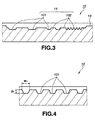
- FIG. 3 is a sectional view taken along line a-a in FIG. 2;
- FIG. 4 is a sectional view taken along line b-b in FIG. 2;
- FIG. 5 is a sectional view taken along line c-c in FIG. 2;
- FIG. 6 is a sectional view taken along line d-d in FIG. 2.
- the magneto-optical disk 10 shown in FIGS. 2 to 6 has recording tracks 11 and grooves 12 that extend along the recording tracks 11. Each land 13 provided between two adjacent grooves 12 is used as a signal-recording region, in which signals will be recorded by means of magneto-optical recording.
- the grooves 12 are discontinuous, and non-groove regions on the tracks are provided at substantially the same position with respect to the tracks.
- Track-counting U-grooves 14 are made in those parts of the non-groove regions (i.e., header regions H) which correspond to the lands 13.
- Each of the track-counting U-grooves 14 is an integral groove consisting of an M part 101 and an S part 102.
- the S part 102 has a predetermined depth measured from the surface of the land 13, which is a reference surface.
- the M part 101 has a predetermined width measured the surface of the S part 102.
- the track-counting U-groove 14 extends along the recording track 11, substantially aligned with the center line of that part of the non-groove region which corresponds to the land 13.
- the depth D 1 of the M part 101 and the depth D 2 of the S part 102, both measured from the surface of the land 13 at the M part 101 satisfy the relation of ⁇ /(4n) ⁇ D 2 ⁇ D 1 ⁇ ⁇ /(2n) , where ⁇ is the wavelength of the reading laser beam and n is the refractive index of the disk substrate.
- both the depth D 1 of the M part 101 and the depth D 2 of the S part 102, measured from the surface of the land 13, are greater than a quarter (1/4) of ⁇ /n and less than 1/2 of ⁇ /n.
- the depth D 1 from the surface of the land 13 of the M part 101 is greater than the depth D 2 from the surface of the land 13 of the S part 102.
- the width W 1 of the M part 101 and the width W 2 of the S part 102 are set at the same value which is equal to or less than half (1/2) the pitch of the recording tracks 11.
- the grooves 12 made in the magneto-optical disk 10 have a depth D 3 from the surfaces of the lands 13.
- the depth D 3 is set at a value that satisfies the relation of D 3 ⁇ ⁇ /(4n) , where ⁇ is the wavelength of the reading laser beam and n is the refractive index of the disk substrate.
- the depth D 3 of the grooves 12 measured from the surfaces of the lands 13 is set less than a quarter (1/4) of ⁇ /n.
- the width W 3 of the grooves 12 is set at half (1/2) the pitch of the recording tracks 11 or less than half (1 ⁇ 2) the pitch of the track 11.
- a seek operation is carried out to access a desired recording track 11.
- a signal is generated by applying the beam to the groove 12.
- the track is counted on the basis of the signal.
- a signal is generated by applying the beam to the track-counting U-groove 14. The track is counted on the basis of this signal.
- the depths D 1 and D 2 of the M part and S part of the track-counting U-groove 14, both measured from the surface of the land 13, are greater than a quarter (1/4) of ⁇ /n and less than half (1 ⁇ 2) the ⁇ /n.
- the depth D 3 of the groove 12 measured from the surfaces of the land 13 is set less than a quarter (1/4) of ⁇ /n.
- This magneto-optical disk 10 is characterized in that the M part 101 of each track-counting U-groove 14 has a depth D 1 from the surface of the land 13, which is greater than the depth D 2 of the S part 102 measured from the surface of the land 13. Therefore, the pit pattern can have a reproducing modulation factor that can be read.
- the magneto-optical disk 10 is characterized, also in that the grooves 12 are discontinuous and that a track-counting U-groove 14 is made in the non-groove region of each track. Therefore, each groove 12 and the track-counting U-groove 14 do not interfere with each other even if the pitch of the recording tracks 11 is short and the width of the land 13 between two adjacent grooves 12 is therefore small.
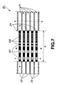
- FIG. 7 is a magnified view of one part of the recording area of a magneto-optical disk 20 according to this invention.
- FIG. 8 is a sectional view taken along line e-e in FIG. 7;
- FIG. 9 is a sectional view taken along line f-f in FIG. 7;
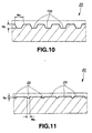
- FIG. 10 is a sectional view taken along line g-g in FIG. 7;
- FIG. 11 is a sectional view taken along line h-h in FIG. 7.
- the magneto-optical disk 20 shown in FIGS. 7 to 11 has grooves 22, each made in the boundaries between two adjacent recording tracks 21. Each land 23 between two adjacent grooves 22 is used as a signal-recording region for recording signals by means of magneto-optical recording.
- the grooves 22 are discontinuous. Non-groove regions are provided at substantially the same position with respect to the recording tracks 21. Track-counting U-grooves 24 are made in those parts of the non-groove regions (i.e., header regions H) which correspond to the lands 23.
- Each of the track-counting U-grooves 24 is an integral groove consisting of an M part 101 and an S part 102.
- the track-counting U-groove 24 extends along the recording track 21, substantially aligned with the center line of that part of the non-groove region which corresponds to the land 23.
- the depth D 4 of the M part 101 and the depth D 5 of the S part 102, both measured from the surface of the land 23 at the M part 101 satisfy the relation of ⁇ /(4n) ⁇ D 4 ⁇ D 5 ⁇ ⁇ /(2n) , where ⁇ is the wavelength of the reading laser beam and n is the refractive index of the disk substrate.
- both the depth D 4 of the M part 101 and the depth D 5 of the S part 102, measured from the surface of the land 23, are greater than a quarter (1/4) of ⁇ /n and less than half (1 ⁇ 2) of ⁇ /n.
- the depth D 4 from the surface of the land 23 of the M part 101 is less than the depth D 5 from the surface of the land 23 of the S part 102.
- the width W 4 of the M part 101 and the width W 5 of the S part 102 are set at the same value which is equal to or less than half (1 ⁇ 2) the pitch of the recording tracks 21.
- the grooves 22 have a depth D 6 from the surfaces of the lands 23.
- the depth D 6 is set at a value that satisfies the relation of D 6 ⁇ ⁇ /(4n) , where ⁇ is the wavelength of the reading laser beam and n is the refractive index of the disk substrate.
- the depth D 6 of the grooves 22 measured from the surfaces of the lands 23 is set less than a quarter (1/4) of ⁇ /n.
- the width W 6 of the grooves 22 is set at half (1 ⁇ 2) the pitch of the recording tracks 21 or less than half (1 ⁇ 2) the pitch of the track 21.
- a seek operation is carried out to access a desired recording track 21.
- a signal is generated by applying the beam to the groove 22.
- the track is counted on the basis of the signal as with the magneto-optical disk 10 described above.
- a signal is generated by applying the beam to the track-counting U-groove 24.
- the track is counted on the basis of this signal.
- the depths D 4 and D 5 of the M part 101 and S part 102 of the track-counting U-groove 24, both measured from the surface of the land 23, are greater than a quarter (1/4) of ⁇ /n.
- the depth D 6 of the groove 22 measured from the surfaces of the land 23 is set less than a quarter (1/4) of ⁇ /n.
- This magneto-optical disk 20 is characterized in that the M part 101 of each track-counting U-groove 14 has a depth D 4 from the surface of the land 23, which is greater than the depth D 5 of the S part 102 measured from the surface of the land 23. Therefore, the pit pattern can have a reproducing modulation factor that can be read.
- the magneto-optical disk 20 is characterized, also in that the grooves 22 are discontinuous and that a track-counting U-groove 24 is made in the non-groove region of each track. Therefore, each groove 22 and the track-counting U-groove 24 do not interfere with each other even if the pitch of the recording tracks 21 is short and the width of the land 23 between two adjacent grooves 22 is therefore small.
- magneto-optical disk 20 it is possible to decrease the track pitch by utilizing, for example, magnetically-induced super resolution, thereby to enhance the surface-recording density.
- FIG. 12 to 16 shows a magneto-optical disk according to the invention.
- the M part 101 and the S part 102 differ in width, imparting to the pit pattern a reproducing modulation factor that can be read.
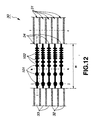
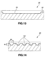
- FIG. 12 is a magnified view of a part of the recording area of a magneto-optical disk 30 according to this embodiment.
- FIG. 13 is a sectional view taken along line i-i in FIG. 12;
- FIG. 14 is a sectional view taken along line j-j in FIG. 12;
- FIG. 15 is a sectional view taken along line k-k in FIG. 12, and
- FIG. 16 is a sectional view taken along line l-l in FIG. 12.
- the magneto-optical disk 30 shown in FIGS. 12 to 16 has grooves 32, each made in the boundaries between two adjacent recording tracks 31. Each land 33 between two adjacent grooves 32 is used as a signal-recording region for recording signals by means of magneto-optical recording.
- the grooves 32 are discontinuous. Non-groove regions are provided at substantially the same position with respect to the recording tracks 31. Track-counting U-grooves 34 are made in those parts of the non-groove regions (i.e., header regions H) which correspond to the lands 33.
- Each of the track-counting U-grooves 34 is an integral groove consisting of an M part 101 and an S part 102.
- the M part 101 has the same depth as the S part 102 and a larger width than the S part 102.
- the track-counting U-groove 34 extends along the recording track 31, substantially aligned with the center line of that part of the non-groove region which corresponds to the land 33.
- the depth D 7 of the M part 101 and the depth D 8 of the S part 102, both measured from the surface of the land 33 satisfy the relation of ⁇ /(4n) ⁇ D 7 ⁇ ⁇ /(2n) and the relation of ⁇ /(4n) ⁇ D 8 ⁇ ⁇ /(2n) , where ⁇ is the wavelength of the reading laser beam and n is the refractive index of the disk substrate.
- both the depth D 7 of the M part 101 and the depth D 8 of the S part 102, measured from the surface of the land 33 are greater than a quarter (1/4) of ⁇ /n and less than half (1 ⁇ 2) of ⁇ /n.
- the depth D 7 from the surface of the land 33 of the M part 101 and the depth D 8 from the surface of the 33 of the S part 102 are set at the same value.
- the width W 7 of the M part 101 and the width W 8 of the S part 102 are set at values which are equal to or less than half (1 ⁇ 2) the pitch of the recording tracks 31.
- the width W 7 of the M part 101 is greater than the width W 8 of the S part 102
- the magneto-optical disk 30 is characterized in that the grooves 32 have a depth D 9 from the surfaces of the lands 33, which is set at a value that satisfies the relation of D 9 ⁇ ⁇ /(4n) , where ⁇ is the wavelength of the reading laser beam and n is the refractive index of the disk substrate.
- the depth D 9 of the grooves 32 measured from the surfaces of the lands 33 is set less than a quarter (1/4) of ⁇ /n.
- the width W 9 of the grooves 32 is set at half (1 ⁇ 2) the pitch of the recording tracks 31 or less than half (1 ⁇ 2) the pitch of the track 31.
- a seek operation is carried out to access a desired recording track 31.
- a signal is generated by applying the beam to the groove 32.
- the track is counted on the basis of the signal as with the magneto-optical disks 10 and 20 described above.
- a signal is generated by applying the beam to the track-counting U-groove 34.
- the track is counted on the basis of this signal.
- the depths D 7 and D 8 of the M part 101 and S part 102 of the track-counting U-groove 34, both measured from the surface of the land 33, are greater than a quarter (1/4) of ⁇ /n.
- the depth D 9 of the groove 32 measured from the surfaces of the land 33 is set less than a quarter (1/4) of ⁇ /n.
- the signal generated by applying the reading laser beam to the groove 32 has the same polarity as the signal generated by applying the reading laser beam to the track-counting U-groove 34 made at a distance of about half (1 ⁇ 2) the track pitch from the groove 32.
- the tracks can be reliably counted on the magneto-optical disk 30.
- the desired track 31 can thereby be accessed.
- This magneto-optical disk 30 is designed such that the M part 101 of each track-counting U-groove 34 has a width W 7 that is greater than the width W 8 of the S part 102. Hence, it is possible to impart to the pit pattern a reproducing modulation factor that can be read.
- the magneto-optical disk 30 is characterized, also in that the grooves 32 are discontinuous and that a track-counting U-groove 34 is made in the non-groove region of each track. Therefore, each groove 32 and the track-counting U-groove 34 do not interfere with each other even if the pitch of the recording tracks 31 is short and the width of the land 33 between two adjacent grooves 32 is therefore small.
- magneto-optical disk 30 it is possible to decrease the pitch of the recording tracks 31 by utilizing, for example, magnetically-induced super resolution, thereby to enhance the surface-recording density very much.
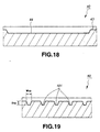
- FIG. 17 is a magnified view of one part of the recording area of a magneto-optical disk 40 according to this invention.
- FIG. 18 is a sectional view taken along line m-m in FIG. 17;
- FIG. 19 is a sectional view taken along line n-n in FIG. 17;
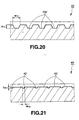
- FIG. 20 is a sectional view taken along line o-o in FIG. 17;
- FIG. 21 is a sectional view taken along line p-p in FIG. 17.
- the magneto-optical disk 40 shown in FIGS. 17 to 21 has grooves 42, each made in the boundaries between two adjacent recording tracks 41.
- Each land 43 between two adjacent grooves 42 is used as a signal-recording region for recording signals by means of magneto-optical recording.
- the grooves 42 are discontinuous. Non-groove regions are provided at substantially the same position with respect to the recording tracks 41. Track-counting U-grooves 44 are made in those parts of the non-groove regions (i.e., header regions H) which correspond to the lands 43.
- Each of the track-counting U-grooves 44 has a predetermined depth from the surface of the land 43, which is the reference surface.
- the U-groove 44 is an integral groove consisting of an M part 101 and an S part 102.
- the track-counting U-groove 44 extends along the recording track 41, substantially aligned with the center line of that part of the non-groove region which corresponds to the land 43.
- the depth D 10 of the M part 101 and the depth D 11 of the S part 102, both measured from the surface of the land 43 satisfy the relation of ⁇ /(4n) ⁇ D 10 ⁇ ⁇ /(2n) and the relation of ⁇ /(4n) ⁇ D 11 ⁇ ⁇ /(2n) , where ⁇ is the wavelength of the reading laser beam and n is the refractive index of the disk substrate.
- both the depth D 10 of the M part 101 and the depth D 11 of the S part 102, measured from the surface of the land 43 are greater than a quarter (1/4) of ⁇ /n and less than half (1 ⁇ 2) of ⁇ /n.
- the depth D 10 from the surface of the land 43 of the M part 101 and the depth D 11 from the surface of the 43 of the S part 102 are set at the same value.
- the width W 10 of the M part 101 and the width W 11 of the S part 102 are set at values which are equal to or less than half (1 ⁇ 2) the pitch of the recording tracks 41. Moreover, the width W 10 of the M part 101 is greater than the width W 11 of the S part 102.
- the magneto-optical disk 40 is characterized in that the grooves 42 have a depth D 12 from the surfaces of the lands 43, which is set at a value that satisfies the relation of D 12 ⁇ ⁇ /(4n) , where ⁇ is the wavelength of the reading laser beam and n is the refractive index of the disk substrate.
- the depth D 12 of the grooves 42 measured from the surfaces of the lands 43 is set less than a quarter (1/4) of ⁇ /n.
- the width W 12 of the grooves 42 is set at half (1 ⁇ 2) the pitch of the recording tracks 41 or less than half (1 ⁇ 2) the pitch of the track 41.
- a seek operation is carried out to access a desired recording track 41.
- a signal is generated by applying the beam to the groove 42.
- the track is counted on the basis of the signal as with the magneto-optical disks 10, 20 and 30 described above.
- a signal is generated by applying the beam to the track-counting U-groove 44.
- the track is counted on the basis of this signal.
- the depths D 10 and D 11 of the M part 101 and S part 102 of the track-counting U-groove 44, both measured from the surface of the land 43, are greater than a quarter (1/4) of ⁇ /n.
- the depth D 12 of the groove 42 measured from the surfaces of the land 43 is set less than a quarter (1/4) of ⁇ /n.
- the signal generated by applying the reading laser beam to the groove 42 has the same polarity as the signal generated by applying the reading laser beam to the track-counting U-groove 44 made at a distance of about half (1 ⁇ 2) the track pitch from the groove 42.
- the tracks can be reliably counted on the magneto-optical disk 40.
- the desired track 41 can thereby be accessed.
- This magneto-optical disk 40 is designed such that the M part 101 of each track-counting U-groove 44 has a width W 10 that is smaller than the width W 11 of the S part 102. Hence, it is possible to impart to the pit pattern a reproducing modulation factor that can be read.
- the magneto-optical disk 40 is characterized, also in that the grooves 42 are discontinuous and that a track-counting U-groove 44 is made in the non-groove region of each track. Therefore, each groove 42 and the track-counting U-groove 44 do not interfere with each other even if the pitch of the recording tracks 41 is short and the width of the land 43 between two adjacent grooves 42 is therefore small.
- magneto-optical disk 40 it is possible to decrease the pitch of the recording tracks 41 by utilizing, for example, magnetically-induced super resolution, thereby to enhance the surface-recording density very much.
- Any magneto-optical disk according to the invention is manufactured by forming a magneto-optical layer on a disk substrate and then a protective layer on the magneto-optical layer, as has been indicated above.
- the substrate of the magneto-optical disk is obtained by injecting disk material heated and melted, into a cavity of a mold set in an injection molding apparatus.
- the mold is composed of a pair of metal mold halves, and a master disk is arranged in the cavity of the mold.
- the master disk has, on its surface, a reversed groove pattern and a reversed pit pattern.
- the master disk used to manufacture the disk substrate is produced in the following manner.
- the major surface of a disc-shaped glass substrate, which has been polished with high precision was coated with a close-contact adhesive.
- the major surface of the glass substrate is then coated with a photoresist having a uniform thickness and being sufficiently sensitive to the wavelength of the laser beam emitted from an exposure apparatus.
- the organic solvent in the photoresist is made to evaporate, whereby a photoresist layer is formed on the glass substrate.
- the glass substrate, now having the photoresist layer formed on it, is set in the exposure apparatus.
- the exposure apparatus applies a laser beam to the photoresist layer formed on the glass substrate, thus scanning the photoresist layer.
- the master disk may be one for manufacturing a magneto-optical disk that has track-counting U-grooves, each having M and S parts of different depths, like the magneto-optical disk 10 shown in FIGS. 2 to 6 and the magneto-optical disk 20 shown in FIGS. 7 to 11.
- two laser beams having different intensifies are applied, respectively, to those two parts of the photoresist layer which corresponds to the M part and S part.
- An latent image corresponding to the M part is formed to a depth
- an latent image corresponding to the S part is formed to a different depth.
- a master resist which has a recess-projection pattern that corresponds to prescribed grooves and track-counting U-grooves.
- a metal film such as a silver film, nickel film or the like, is formed on the major surface of the master resist which has the recess-projection pattern, by means of sputtering, vapor deposition, electroless plating, or the like.
- the master resist now having the metal film is set in an electro-plating apparatus. Electro-plating is carried out, using the metal film as an electrode. An electro-plated layer is thereby formed on the major surface of the master resist.
- the master resist is peeled from the metal film and the electro-plated layer.
- the residual metal film is removed by means of pressing.
- a master disk is thereby manufactured.
- a latent image corresponding to the track-counting U-grooves can be reliably formed, merely by changing the laser beam to be applied to the photoresist layer, in terms of intensity or diameter.
- the magneto-optical disk according to the present invention can therefore be manufactured with ease.
- the optical recording medium according to this invention has detection patterns, each provided in a non-groove region and used to optically detect that the light spot of a reading laser beam has crossed a recording track. In the course of accessing a track, it is detected that the light spot moves across a recording track when the light spot moves over a detection pattern. This makes it possible to access a track at high speed.
- the optical recording medium substrate according to the invention has detection patterns, each provided in a non-groove region and used to optically detect that the light spot of a reading laser beam has crossed a recording track.
- the light spot is detected to cross a recording track when it moves over the detection pattern. Any recording track can therefore be accessed reliably at high speed.
- a laser beam of a certain intensity is applied to a part of a photosensitive layer, which corresponds to a pit pattern, and a laser beam of a different intensity is applied to the other part of the layer, in the process of forming a latent image of a detection pattern on the photosensitive layer by applying laser beams thereto. Therefore, a latent image of a specific depth is formed on the part corresponding to the pit pattern, while a latent image of a different depth is formed on the other part. Thus, it is easy to form a latent image having a specific depth at the part corresponding to the pit pattern and a different depth at the other part.
- a laser beam of a certain diameter is applied to a part of a photosensitive layer, which corresponds to a pit pattern, and a laser beam of a different diameter is applied to the other part of the layer, in the process of forming a latent image of a detection pattern on the photosensitive layer by applying laser beams thereto.
- a latent image having a certain width is formed on the part corresponding to the pit pattern, while a latent image having a different width is formed on the other part.
- tracks are counted at non-groove regions on the basis of the information optically obtained from a detection pattern, and at groove regions on the basis of the information optically obtained from the grooves. Hence, the tracks can be reliably counted, making it possible to access a desired track at high speed.
Landscapes
- Engineering & Computer Science (AREA)
- Manufacturing & Machinery (AREA)
- Optical Recording Or Reproduction (AREA)
- Optical Record Carriers And Manufacture Thereof (AREA)
- Manufacturing Optical Record Carriers (AREA)
Applications Claiming Priority (3)
| Application Number | Priority Date | Filing Date | Title |
|---|---|---|---|
| JP15627798A JP3615054B2 (ja) | 1998-06-04 | 1998-06-04 | 光学記録媒体 |
| JP15627798 | 1998-06-04 | ||
| PCT/JP1999/003006 WO1999063534A1 (en) | 1998-06-04 | 1999-06-04 | Optical recording medium |
Publications (2)
| Publication Number | Publication Date |
|---|---|
| EP1003163A1 true EP1003163A1 (de) | 2000-05-24 |
| EP1003163A4 EP1003163A4 (de) | 2001-02-14 |
Family
ID=15624309
Family Applications (1)
| Application Number | Title | Priority Date | Filing Date |
|---|---|---|---|
| EP99923917A Withdrawn EP1003163A4 (de) | 1998-06-04 | 1999-06-04 | Optischer aufzeichnungsträger |
Country Status (6)
| Country | Link |
|---|---|
| US (1) | US6800348B2 (de) |
| EP (1) | EP1003163A4 (de) |
| JP (1) | JP3615054B2 (de) |
| KR (1) | KR20010022622A (de) |
| CN (1) | CN1274459A (de) |
| WO (1) | WO1999063534A1 (de) |
Cited By (1)
| Publication number | Priority date | Publication date | Assignee | Title |
|---|---|---|---|---|
| EP1403859A4 (de) * | 2001-06-29 | 2007-03-07 | Sony Corp | Optische aufzeichnung, wiedergabemedium, muttermatrix zur herstellung einer optischen aufzeichnung, wiedergabemedium und optische aufzeichnung, wiedergabegerät |
Families Citing this family (6)
| Publication number | Priority date | Publication date | Assignee | Title |
|---|---|---|---|---|
| JP2002222548A (ja) * | 2001-01-26 | 2002-08-09 | Sony Corp | 光記録媒体、光記録媒体製造用原盤、光記録媒体製造用原盤の製造装置、光記録媒体製造用原盤の製造方法 |
| JP2002298343A (ja) * | 2001-03-28 | 2002-10-11 | Nec Corp | 光ディスクの記録再生方法および記録再生装置 |
| JP2004005872A (ja) * | 2002-04-09 | 2004-01-08 | Matsushita Electric Ind Co Ltd | 光ディスク原盤作製方法および光ディスクとその製造方法 |
| JP2006252743A (ja) * | 2005-03-08 | 2006-09-21 | Qinghua Univ | マルチレベル読み出し専用光ディスク及びその製造方法 |
| JP5202534B2 (ja) * | 2006-10-16 | 2013-06-05 | トムソン ライセンシング | ポジティブマーク群及びネガティブマーク群を有するトラック群を備える光学記憶媒体、並びにその光学記憶媒体製造のためのスタンパ及び製造方法 |
| US20140250482A1 (en) * | 2013-03-01 | 2014-09-04 | Prime Image Delaware, Inc. | System and method for removing a pause in a delayed remote broadcast interview |
Family Cites Families (16)
| Publication number | Priority date | Publication date | Assignee | Title |
|---|---|---|---|---|
| JPH0799592B2 (ja) | 1985-10-02 | 1995-10-25 | 松下電器産業株式会社 | 光学式情報記憶担体 |
| JPH0478034A (ja) * | 1990-05-15 | 1992-03-12 | Toshiba Corp | 光情報記録媒体及び光情報記録再生装置 |
| US5406546A (en) * | 1992-10-05 | 1995-04-11 | Tdk Corporation | Magneto-optical disk |
| JPH06282849A (ja) * | 1993-01-29 | 1994-10-07 | Sony Corp | 光記録媒体、光記録媒体の記録再生装置及び再生装置 |
| JPH06302031A (ja) | 1993-02-22 | 1994-10-28 | Sharp Corp | 光磁気記録媒体および光磁気記録装置 |
| JPH0714230A (ja) | 1993-06-25 | 1995-01-17 | Matsushita Electric Ind Co Ltd | 光磁気記録媒体及びその再生方法 |
| US5638354A (en) | 1993-07-16 | 1997-06-10 | Ricoh Company, Ltd. | Optical information recording medium |
| JP3375694B2 (ja) | 1993-07-19 | 2003-02-10 | パイオニア株式会社 | 光磁気ディスク及び光磁気ディスク再生装置 |
| US5581539A (en) * | 1994-08-12 | 1996-12-03 | Mitsubishi Chemical Corporation | Optical recording medium |
| JP3707835B2 (ja) * | 1995-08-10 | 2005-10-19 | 株式会社東芝 | 光ディスク装置 |
| JP3063598B2 (ja) * | 1995-12-01 | 2000-07-12 | 三菱電機株式会社 | 光ディスクおよび光ディスク装置 |
| JPH09251668A (ja) * | 1996-03-15 | 1997-09-22 | Sony Corp | 光学式記録媒体 |
| JPH09259439A (ja) * | 1996-03-19 | 1997-10-03 | Fujitsu Ltd | 光記録媒体及びトラックを計数する方法 |
| JP3063613B2 (ja) * | 1996-03-25 | 2000-07-12 | 三菱電機株式会社 | 光ディスク媒体及び光ディスク装置 |
| JP3091876B2 (ja) | 1996-08-30 | 2000-09-25 | 富士通株式会社 | 光記録媒体及びドライブ装置 |
| JP3753517B2 (ja) * | 1997-10-20 | 2006-03-08 | 富士通株式会社 | 光記録媒体ドライブ装置 |
-
1998
- 1998-06-04 JP JP15627798A patent/JP3615054B2/ja not_active Expired - Fee Related
-
1999
- 1999-06-04 CN CN99801301A patent/CN1274459A/zh active Pending
- 1999-06-04 WO PCT/JP1999/003006 patent/WO1999063534A1/ja not_active Ceased
- 1999-06-04 US US09/485,206 patent/US6800348B2/en not_active Expired - Fee Related
- 1999-06-04 KR KR1020007001216A patent/KR20010022622A/ko not_active Ceased
- 1999-06-04 EP EP99923917A patent/EP1003163A4/de not_active Withdrawn
Cited By (1)
| Publication number | Priority date | Publication date | Assignee | Title |
|---|---|---|---|---|
| EP1403859A4 (de) * | 2001-06-29 | 2007-03-07 | Sony Corp | Optische aufzeichnung, wiedergabemedium, muttermatrix zur herstellung einer optischen aufzeichnung, wiedergabemedium und optische aufzeichnung, wiedergabegerät |
Also Published As
| Publication number | Publication date |
|---|---|
| EP1003163A4 (de) | 2001-02-14 |
| JPH11353656A (ja) | 1999-12-24 |
| JP3615054B2 (ja) | 2005-01-26 |
| WO1999063534A1 (en) | 1999-12-09 |
| US20020127365A1 (en) | 2002-09-12 |
| KR20010022622A (ko) | 2001-03-26 |
| CN1274459A (zh) | 2000-11-22 |
| US6800348B2 (en) | 2004-10-05 |
Similar Documents
| Publication | Publication Date | Title |
|---|---|---|
| EP0657884B1 (de) | Verfahren zum magnetischen Aufzeichnen und Wiedergeben von Daten, magnetischer Auzeichnungsträger, sein Herstellungsverfahren und Gerät zur magnetischen Aufzeichnung | |
| US5933411A (en) | Optical recording medium having a wobbling section for recording address information and methods of recording and reproduction using same | |
| US5676854A (en) | Optical memory having narrowed track pitch | |
| EP0656625B1 (de) | Optische Scheibe und Verfahren zur Wiedergabe darauf aufgezeichneter Information | |
| EP0306324B1 (de) | Optisches Speichersystem | |
| US6800348B2 (en) | Optical recording medium | |
| JP3512583B2 (ja) | 光ディスク | |
| JP2644840B2 (ja) | 光ディスク | |
| US5856969A (en) | Optical disk which reduces cross erasure of data recorded on lands and grooves | |
| US5654953A (en) | Optical disk and method of manufacturing the same | |
| EP0982716B1 (de) | Optisches Aufzeichnungsmedium und Matrizenplatte zur Herstellung desgleichen | |
| JP3108671B2 (ja) | 光磁気メモリ素子 | |
| JP4040563B2 (ja) | 光ディスク装置 | |
| JP2863431B2 (ja) | 光磁気記録再生装置 | |
| EP1063642B1 (de) | Optisches Aufzeichnungsmedium | |
| JP2848992B2 (ja) | 光記録媒体及びそれに用いる光記録媒体用基板 | |
| US6208595B1 (en) | Magneto-optical recording medium | |
| JP3108682B2 (ja) | 光磁気メモリ素子の製造方法 | |
| JP3371193B2 (ja) | 光ディスク、その原盤及びこれらの製造方法 | |
| JPH06168451A (ja) | 光ディスク装置 | |
| JP2001006219A (ja) | 光記録媒体、光記録媒体用基板及び光記録媒体製造用原盤 | |
| JPH08273204A (ja) | 光ディスク及び光ディスクの製造方法 | |
| JP2002175627A (ja) | 光記録媒体用スタンパの作製方法およびそのスタンパを使用して作製した光記録媒体 | |
| JP2566111C (de) | ||
| KR20030080877A (ko) | 글래스 디스크의 트랙형성방법 및 트랙킹 방법 |
Legal Events
| Date | Code | Title | Description |
|---|---|---|---|
| PUAI | Public reference made under article 153(3) epc to a published international application that has entered the european phase |
Free format text: ORIGINAL CODE: 0009012 |
|
| 17P | Request for examination filed |
Effective date: 20000203 |
|
| AK | Designated contracting states |
Kind code of ref document: A1 Designated state(s): DE FR GB NL |
|
| A4 | Supplementary search report drawn up and despatched |
Effective date: 20010103 |
|
| AK | Designated contracting states |
Kind code of ref document: A4 Designated state(s): DE FR GB NL |
|
| RIC1 | Information provided on ipc code assigned before grant |
Free format text: 7G 11B 7/24 A, 7G 11B 11/10 B, 7G 11B 7/007 B, 7G 11B 7/085 B, 7G 11B 7/26 B, 7G 11B 7/013 B |
|
| STAA | Information on the status of an ep patent application or granted ep patent |
Free format text: STATUS: THE APPLICATION HAS BEEN WITHDRAWN |
|
| 18W | Application withdrawn |
Effective date: 20050727 |