EP1003189A2 - Lèves vitres electriques pour véhicules à moteur - Google Patents
Lèves vitres electriques pour véhicules à moteur Download PDFInfo
- Publication number
- EP1003189A2 EP1003189A2 EP99121817A EP99121817A EP1003189A2 EP 1003189 A2 EP1003189 A2 EP 1003189A2 EP 99121817 A EP99121817 A EP 99121817A EP 99121817 A EP99121817 A EP 99121817A EP 1003189 A2 EP1003189 A2 EP 1003189A2
- Authority
- EP
- European Patent Office
- Prior art keywords
- control
- lever
- motors
- knob
- cup
- Prior art date
- Legal status (The legal status is an assumption and is not a legal conclusion. Google has not performed a legal analysis and makes no representation as to the accuracy of the status listed.)
- Withdrawn
Links
Images

Classifications
-
- H—ELECTRICITY
- H01—ELECTRIC ELEMENTS
- H01H—ELECTRIC SWITCHES; RELAYS; SELECTORS; EMERGENCY PROTECTIVE DEVICES
- H01H25/00—Switches with compound movement of handle or other operating part
- H01H25/04—Operating part movable angularly in more than one plane, e.g. joystick
-
- E—FIXED CONSTRUCTIONS
- E05—LOCKS; KEYS; WINDOW OR DOOR FITTINGS; SAFES
- E05F—DEVICES FOR MOVING WINGS INTO OPEN OR CLOSED POSITION; CHECKS FOR WINGS; WING FITTINGS NOT OTHERWISE PROVIDED FOR, CONCERNED WITH THE FUNCTIONING OF THE WING
- E05F15/00—Power-operated mechanisms for wings
- E05F15/40—Safety devices, e.g. detection of obstructions or end positions
-
- E—FIXED CONSTRUCTIONS
- E05—LOCKS; KEYS; WINDOW OR DOOR FITTINGS; SAFES
- E05F—DEVICES FOR MOVING WINGS INTO OPEN OR CLOSED POSITION; CHECKS FOR WINGS; WING FITTINGS NOT OTHERWISE PROVIDED FOR, CONCERNED WITH THE FUNCTIONING OF THE WING
- E05F15/00—Power-operated mechanisms for wings
- E05F15/60—Power-operated mechanisms for wings using electrical actuators
- E05F15/603—Power-operated mechanisms for wings using electrical actuators using rotary electromotors
- E05F15/665—Power-operated mechanisms for wings using electrical actuators using rotary electromotors for vertically-sliding wings
- E05F15/689—Power-operated mechanisms for wings using electrical actuators using rotary electromotors for vertically-sliding wings specially adapted for vehicle windows
- E05F15/695—Control circuits therefor
-
- H—ELECTRICITY
- H01—ELECTRIC ELEMENTS
- H01H—ELECTRIC SWITCHES; RELAYS; SELECTORS; EMERGENCY PROTECTIVE DEVICES
- H01H1/00—Contacts
- H01H1/12—Contacts characterised by the manner in which co-operating contacts engage
- H01H1/36—Contacts characterised by the manner in which co-operating contacts engage by sliding
- H01H1/40—Contact mounted so that its contact-making surface is flush with adjoining insulation
- H01H1/403—Contacts forming part of a printed circuit
-
- E—FIXED CONSTRUCTIONS
- E05—LOCKS; KEYS; WINDOW OR DOOR FITTINGS; SAFES
- E05F—DEVICES FOR MOVING WINGS INTO OPEN OR CLOSED POSITION; CHECKS FOR WINGS; WING FITTINGS NOT OTHERWISE PROVIDED FOR, CONCERNED WITH THE FUNCTIONING OF THE WING
- E05F15/00—Power-operated mechanisms for wings
-
- E—FIXED CONSTRUCTIONS
- E05—LOCKS; KEYS; WINDOW OR DOOR FITTINGS; SAFES
- E05Y—INDEXING SCHEME ASSOCIATED WITH SUBCLASSES E05D AND E05F, RELATING TO CONSTRUCTION ELEMENTS, ELECTRIC CONTROL, POWER SUPPLY, POWER SIGNAL OR TRANSMISSION, USER INTERFACES, MOUNTING OR COUPLING, DETAILS, ACCESSORIES, AUXILIARY OPERATIONS NOT OTHERWISE PROVIDED FOR, APPLICATION THEREOF
- E05Y2400/00—Electronic control; Electrical power; Power supply; Power or signal transmission; User interfaces
- E05Y2400/80—User interfaces
- E05Y2400/85—User input means
- E05Y2400/852—Sensors
- E05Y2400/854—Switches
-
- E—FIXED CONSTRUCTIONS
- E05—LOCKS; KEYS; WINDOW OR DOOR FITTINGS; SAFES
- E05Y—INDEXING SCHEME ASSOCIATED WITH SUBCLASSES E05D AND E05F, RELATING TO CONSTRUCTION ELEMENTS, ELECTRIC CONTROL, POWER SUPPLY, POWER SIGNAL OR TRANSMISSION, USER INTERFACES, MOUNTING OR COUPLING, DETAILS, ACCESSORIES, AUXILIARY OPERATIONS NOT OTHERWISE PROVIDED FOR, APPLICATION THEREOF
- E05Y2400/00—Electronic control; Electrical power; Power supply; Power or signal transmission; User interfaces
- E05Y2400/80—User interfaces
- E05Y2400/85—User input means
- E05Y2400/856—Actuation thereof
- E05Y2400/858—Actuation thereof by body parts, e.g. by feet
- E05Y2400/86—Actuation thereof by body parts, e.g. by feet by hand
-
- E—FIXED CONSTRUCTIONS
- E05—LOCKS; KEYS; WINDOW OR DOOR FITTINGS; SAFES
- E05Y—INDEXING SCHEME ASSOCIATED WITH SUBCLASSES E05D AND E05F, RELATING TO CONSTRUCTION ELEMENTS, ELECTRIC CONTROL, POWER SUPPLY, POWER SIGNAL OR TRANSMISSION, USER INTERFACES, MOUNTING OR COUPLING, DETAILS, ACCESSORIES, AUXILIARY OPERATIONS NOT OTHERWISE PROVIDED FOR, APPLICATION THEREOF
- E05Y2800/00—Details, accessories and auxiliary operations not otherwise provided for
- E05Y2800/40—Physical or chemical protection
- E05Y2800/424—Physical or chemical protection against unintended use, e.g. protection against vandalism or sabotage
-
- E—FIXED CONSTRUCTIONS
- E05—LOCKS; KEYS; WINDOW OR DOOR FITTINGS; SAFES
- E05Y—INDEXING SCHEME ASSOCIATED WITH SUBCLASSES E05D AND E05F, RELATING TO CONSTRUCTION ELEMENTS, ELECTRIC CONTROL, POWER SUPPLY, POWER SIGNAL OR TRANSMISSION, USER INTERFACES, MOUNTING OR COUPLING, DETAILS, ACCESSORIES, AUXILIARY OPERATIONS NOT OTHERWISE PROVIDED FOR, APPLICATION THEREOF
- E05Y2900/00—Application of doors, windows, wings or fittings thereof
- E05Y2900/50—Application of doors, windows, wings or fittings thereof for vehicles
- E05Y2900/53—Type of wing
- E05Y2900/55—Windows
-
- H—ELECTRICITY
- H01—ELECTRIC ELEMENTS
- H01H—ELECTRIC SWITCHES; RELAYS; SELECTORS; EMERGENCY PROTECTIVE DEVICES
- H01H2300/00—Orthogonal indexing scheme relating to electric switches, relays, selectors or emergency protective devices covered by H01H
- H01H2300/01—Application power window
Definitions
- the present invention refers to a separate switch that controls all the motors for the power windows of the motor vehicle, either the front ones only or the rear ones with optional control functions for all the motors together or inhibition of the control of the back windows from the rear of the motor vehicle (safety measure for children).
- the present motor vehicle devices present groups of motors for power windows located in different parts of the motor vehicle, for example on the door handles, on the central tunnel or on the dashboard, according to the stylistic/ergonomic choices of the manufacturers.
- Said devices share the characteristic that each window is controlled by a switch for the up-and-down mode, both automatically and manually.
- switches are gathered on a single metal support mounted on the door on the driver side or on the tunnel, being integrated by an additional switch to lock the controls of the rear part of the motor vehicle (safety measure for children). It becomes evident that the utilisation of so large a number of switches means high costs.
- German Patent n°3524439 it is also known, among the electrical controls of the devices of the motor vehicle, a device to adjust the position of the rearview mirrors of a motor vehicle, presenting a separate control consisting of a lever housed in a way such that it can be rotated and inclined in order to select and control the two electrical motors of each mirror.
- reference number 1 indicates the envelope of the separate control with a snap mounted bottom 3 and including electrical contacts 4.
- a control lever 5 resting on a fulcrum on the envelope 1, is adapted, when inclined on a side, to move a bond 7 with a pair of pin contacts 9.
- the lever 5 is kept in a vertical position because its lower edge is provided by a retractable rounded point 10 which is pushed by a pressure spring into a conic notch 11, made in the bottom 3 at the vertical axis of the envelope 1.
- a side push on the knob 13 of the lever 5, allows the lever to be inclined in an unstable position, with a rotation around the point 14 located at the wall of the cover 1, and the point 10 to slide on the surface of the notch 11.
- the lever 5 may be snap rotated into six selection positions, that is a neutral position, a position of simultaneous control of the four motors of the power windows, and a control position for each of the motors.
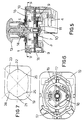
- a release control integrally located rotatably to the lever 5 above the printed circuit 9. It is made of an arch support 16 provided with two diametrically opposite caps 17, stressed into diametral expansion by a spring 18.
- the caps 17 can slide on the inner surface of a ring guide 19, with a basically rectangular plan, the hole of which presents two recesses 21 and 22, at the main axis and four additional recesses, 23, 24, 25 and 26 at the diagonals.
- An action on the knob 13 causes the rotation of the support 16 that drags the caps 17. They end snap positioned into two of the facing recesses made on the inner wall of the ring.
- Figures 1 to 4 show a possible location of the separate control on a part of the inner covering of the passenger compartment 30, more in particular on the dashboard or on the central tunnel between the seats.
- the covering 30 forms a cup 31 in which the upper part of the lever 5 protrudes with the control knob 13.
- the envelope 1 with the bottom 3 is hidden in the part under the cup 31.
- the wall of the covering 30 forms, on the edge of the cup 31, a radial projection 32 protruding towards the centre of the cup, till it covers part of the control knob 13.
- On the upper surface of the knob there are two position marks 33 and 34, of different design, which respectively indicate the portion of the knob in the rotation field of which either all the windows or the front windows only are selected, and the portion where the rear windows or the neutral position are selected.
- References marks 35 are present also on the inner wall of the cup, in order to indicate the position of the main axis (neutral or all) and the two diagonals (right, left).
- the corresponding mark is placed on the reference indicated on the cup (for example front left in figure 1) and the knob 13 is pulled in the direction of arrow A in order to lift the window or is pushed in the direction of arrow B in order to lower it.
- the projection 32 has been expressly made to prevent the knob to be accidentally pushed and moved to the right in figures 1, 2 and 3, in order to prevent the windows from being closed when it is not desired, for example to prevent children from doing that. It will be therefore recommended that the control be mounted in such a way that when the knob is moved to the right one or all the windows are lowered.
Landscapes
- Control Of Multiple Motors (AREA)
- Electric Propulsion And Braking For Vehicles (AREA)
- Window Of Vehicle (AREA)
- Power-Operated Mechanisms For Wings (AREA)
Applications Claiming Priority (2)
| Application Number | Priority Date | Filing Date | Title |
|---|---|---|---|
| ITTO980965 IT1305185B1 (it) | 1998-11-17 | 1998-11-17 | Comando per gli alzacristalli elettrici di un autoveicolo. |
| ITTO980965 | 1998-11-17 |
Publications (2)
| Publication Number | Publication Date |
|---|---|
| EP1003189A2 true EP1003189A2 (fr) | 2000-05-24 |
| EP1003189A3 EP1003189A3 (fr) | 2002-10-02 |
Family
ID=11417186
Family Applications (1)
| Application Number | Title | Priority Date | Filing Date |
|---|---|---|---|
| EP99121817A Withdrawn EP1003189A3 (fr) | 1998-11-17 | 1999-11-04 | Lèves vitres electriques pour véhicules à moteur |
Country Status (2)
| Country | Link |
|---|---|
| EP (1) | EP1003189A3 (fr) |
| IT (1) | IT1305185B1 (fr) |
Cited By (2)
| Publication number | Priority date | Publication date | Assignee | Title |
|---|---|---|---|---|
| FR2828707A1 (fr) * | 2001-08-14 | 2003-02-21 | Renault | Systeme de commande pour vitres electriques de vehicule automobile |
| WO2003055722A1 (fr) * | 2001-12-31 | 2003-07-10 | Lear Automotive (Eeds) Spain, S.L. | Circuit de communication et interrupteur de commande de mecanismes leve-vitre de vehicules |
Family Cites Families (7)
| Publication number | Priority date | Publication date | Assignee | Title |
|---|---|---|---|---|
| JPS5670936U (fr) * | 1979-11-05 | 1981-06-11 | ||
| DE3524439A1 (de) * | 1985-07-09 | 1987-01-22 | Kirsten Elektrotech | Schalter fuer das einstellen von mindestens zwei spiegeln eines kraftfahrzeuges |
| DE3721267A1 (de) * | 1987-06-27 | 1989-01-05 | Daimler Benz Ag | Steuereinheit zur handsteuerung von reversierbaren elektrischen verstelleinrichtungen |
| DE69022118T2 (de) * | 1989-05-30 | 1996-02-15 | Ichiko Industries Ltd | Fernsteuerungsschalter für die Lageeinstellung von Kraftfahrzeugspiegeln. |
| DE4008641A1 (de) * | 1990-03-17 | 1991-09-19 | Daimler Benz Ag | Steuervorrichtung zur handverstellung von reversierbaren elektrischen verstelleinrichtungen |
| JP3219353B2 (ja) * | 1994-08-26 | 2001-10-15 | アルプス電気株式会社 | 回転操作型スイッチおよび多方向入力装置 |
| FR2731090B1 (fr) * | 1995-02-23 | 1997-05-16 | Peugeot | Actionneur multifonctions notamment pour vehicule automobile |
-
1998
- 1998-11-17 IT ITTO980965 patent/IT1305185B1/it active
-
1999
- 1999-11-04 EP EP99121817A patent/EP1003189A3/fr not_active Withdrawn
Cited By (2)
| Publication number | Priority date | Publication date | Assignee | Title |
|---|---|---|---|---|
| FR2828707A1 (fr) * | 2001-08-14 | 2003-02-21 | Renault | Systeme de commande pour vitres electriques de vehicule automobile |
| WO2003055722A1 (fr) * | 2001-12-31 | 2003-07-10 | Lear Automotive (Eeds) Spain, S.L. | Circuit de communication et interrupteur de commande de mecanismes leve-vitre de vehicules |
Also Published As
| Publication number | Publication date |
|---|---|
| EP1003189A3 (fr) | 2002-10-02 |
| ITTO980965A1 (it) | 2000-05-17 |
| IT1305185B1 (it) | 2001-04-10 |
Similar Documents
| Publication | Publication Date | Title |
|---|---|---|
| EP0537718B1 (fr) | Accoudoir pour véhicules | |
| EP2216201B1 (fr) | Unité de commande de siège électrique | |
| US6904995B2 (en) | Arrangement of operator control elements | |
| US6833517B2 (en) | Multiple switch device | |
| US20010052715A1 (en) | Control panel for a vehicle | |
| US5508897A (en) | Overhead lamp assembly | |
| US5777394A (en) | Seat adjusting switch particularly for vehicle seats | |
| US20040244524A1 (en) | Electronically actuated shifter mechanism | |
| EP0200247A2 (fr) | Dispositif électrique pour allumer rapidement des cigares et des cigarettes, en particulier pour véhicule automobile | |
| KR100962157B1 (ko) | 인터페이스 장치 | |
| US6538220B2 (en) | Switch pod assembly | |
| EP1003189A2 (fr) | Lèves vitres electriques pour véhicules à moteur | |
| RU2640373C2 (ru) | Подлокотник для автомобиля | |
| US20190219150A1 (en) | Shift device | |
| US6150620A (en) | Steering column switch for a motor vehicle | |
| US6601905B1 (en) | Convertible power top and power window switch | |
| US6555769B2 (en) | Key-type control device | |
| US20080012413A1 (en) | Seat Adjustment Mechanism Comprising a Rotative Actuating Element | |
| EP1340647B1 (fr) | Commande manuelle pour le réglage de la position d'un siège | |
| EP3670234B1 (fr) | Agencement d'une unité de fonctionnement dans un véhicule à moteur | |
| US6121558A (en) | Steering column switch | |
| JPS6337325Y2 (fr) | ||
| JPH10169309A (ja) | パワーウインドウスイッチ | |
| JPS6411493B2 (fr) | ||
| KR102506453B1 (ko) | 차량용 멀티 오퍼레이팅 스위치 유닛 |
Legal Events
| Date | Code | Title | Description |
|---|---|---|---|
| PUAI | Public reference made under article 153(3) epc to a published international application that has entered the european phase |
Free format text: ORIGINAL CODE: 0009012 |
|
| AK | Designated contracting states |
Kind code of ref document: A2 Designated state(s): AT BE CH CY DE DK ES FI FR GB GR IE IT LI LU MC NL PT SE |
|
| AX | Request for extension of the european patent |
Free format text: AL;LT;LV;MK;RO;SI |
|
| RAP3 | Party data changed (applicant data changed or rights of an application transferred) |
Owner name: BITRON S.P.A. |
|
| PUAL | Search report despatched |
Free format text: ORIGINAL CODE: 0009013 |
|
| AK | Designated contracting states |
Kind code of ref document: A3 Designated state(s): AT BE CH CY DE DK ES FI FR GB GR IE IT LI LU MC NL PT SE |
|
| AX | Request for extension of the european patent |
Free format text: AL;LT;LV;MK;RO;SI |
|
| STAA | Information on the status of an ep patent application or granted ep patent |
Free format text: STATUS: THE APPLICATION IS DEEMED TO BE WITHDRAWN |
|
| 18D | Application deemed to be withdrawn |
Effective date: 20011201 |