EP1003215A2 - Dissipateur de chaleur avec bride intégrale auto-bloquante - Google Patents
Dissipateur de chaleur avec bride intégrale auto-bloquante Download PDFInfo
- Publication number
- EP1003215A2 EP1003215A2 EP99308907A EP99308907A EP1003215A2 EP 1003215 A2 EP1003215 A2 EP 1003215A2 EP 99308907 A EP99308907 A EP 99308907A EP 99308907 A EP99308907 A EP 99308907A EP 1003215 A2 EP1003215 A2 EP 1003215A2
- Authority
- EP
- European Patent Office
- Prior art keywords
- heat
- alignment
- clamping arm
- recited
- heat sink
- Prior art date
- Legal status (The legal status is an assumption and is not a legal conclusion. Google has not performed a legal analysis and makes no representation as to the accuracy of the status listed.)
- Withdrawn
Links
Images


Classifications
-
- H—ELECTRICITY
- H10—SEMICONDUCTOR DEVICES; ELECTRIC SOLID-STATE DEVICES NOT OTHERWISE PROVIDED FOR
- H10W—GENERIC PACKAGES, INTERCONNECTIONS, CONNECTORS OR OTHER CONSTRUCTIONAL DETAILS OF DEVICES COVERED BY CLASS H10
- H10W40/00—Arrangements for thermal protection or thermal control
- H10W40/60—Securing means for detachable heating or cooling arrangements, e.g. clamps
- H10W40/641—Snap-on arrangements, e.g. clips
Definitions
- the present invention is directed, in general, to a heat sink and, more specifically, to a heat sink having an integral self-locking clamp and component alignment features.
- heat sinks use some form of mechanical method to attach the heat-generating component to the heat sink.
- the most common methods are: adhesives, spring clamping devices, or hold-down brackets with a mechanical fastener, such as a bolt.
- Adhesives have well known disadvantages associated with storage and handling.
- the heat sinks are usually made of two pieces: a main heat sink body, and a separate retaining clamp.
- the clamp is a flat spring that at least partially surrounds the component and engages detents or notches in the main heat sink body.
- the retaining clamp may have a hook on one end that engages an aperture in the main body and is secured to the body by a machine screw.
- the technician typically must assemble the parts and the component, or apply the adhesive by hand.
- This hand assembly often results in imprecise alignment of the component and the heat sink. Additionally, this hand alignment requires an appreciable amount of time, which slows down production and ultimately increases the cost of the assembly.
- the heat sink incorporates structural support features for the component
- cooperative alignment of the heat sink and the component is essential so that the assembly readily aligns with the intended apertures on the printed wiring board (PWB).
- PWB printed wiring board
- This alignment problem may be overcome by allowing some variability in locating the component on the heat sink, i.e. , the component may be shifted laterally when in contact with the heat sink so as to align the leads and supports with the appropriate apertures on the PWB. Of course, this variability may lead to a loose junction between the component and the heat sink. While these fastening methods are adequate in retaining the component on the heat sink, there is a significant cost associated with the time it takes an assembler to make the mechanical attachment of the component to the heat sink.
- the present invention provides a heat sink for use with a heat-generating electrical component.
- the heat sink comprises a heat-conducting body having first and second opposing edges, and a clamping arm.
- the heat sink is configured to at least partially support the electrical, heat-generating component.
- the heat-conducting body further includes a receiving catch coupled to the first edge.
- the clamping arm has a first end hinged to the heat-conducting body at the second edge and a second end configured to cooperatively engage the receiving catch and maintain the clamping arm in a locked position.
- the heat sink further includes alignment bosses configured to receive and align the electrical, heat-generating component.
- the heat-conducting body has a mounting face that opposes the clamping arm when the clamping arm is in the locked position, and the alignment bosses are formed on the mounting face.
- the clamping arm has an interior face that opposes the heat-conducting body when the clamping arm is in the locked position, and the alignment bosses are formed on the interior face.
- the alignment bosses may be formed on both the heat-conducting body and the clamping arm.
- the heat-conducting body may also include a fiducial aperture configured to align the electrical heat-generating component in a position to cooperatively engage the plurality of alignment bosses.
- the heat sink in yet another embodiment, may include solderable alignment tangs configured to engage corresponding alignment apertures in a printed wiring board.
- the heat sink may also comprise a heat-dissipating fin.
- the first end further includes a compliant hinge integrally formed with the heat-conducting body and the clamping arm.
- the heat sink further includes alignment bosses and alignment tangs. The alignment bosses and alignment tangs are cooperatively positioned to align an electrical lead of the electrical component to a corresponding alignment aperture formed in a printed wiring board when the electrical component is retained by the heat sink.
- the heat-conducting body includes a body flute configured to stiffen the heat-conducting body, and allow the heat sink to be formed from the thinnest possible material.
- the clamping arm may include a clamping arm flute configured to stiffen the clamping arm.
- the heat sink including heat-conducting body and the clamping arm, may be integrally formed from aluminum, copper, or steel.
- a heat sink 100 comprises a heat-conducting body 110 and a clamping arm 120.
- the heat sink 100 may be fabricated from a sheet of any suitable heat-conducting material; however, tin-plated or tin/lead-plated steel, copper, and aluminum are preferred materials. These materials are especially useful because they are: relatively inexpensive, good heat conductors, readily formed, common in the electronics industry and, with the exception of aluminum, may be readily soldered. Tin-plated or lead-plated steel is highly desirable because of very low cost and high structural strength.
- the heat-conducting body 110 is formed with first and second opposing edges 111, 112 and the clamping arm has first and second ends 121, 122.
- a compliant hinge 123 is integrally formed between the second edge 112 and the first end 121 of the clamping arm 120.
- a receiving catch 113 is formed at the first edge 111 of the heat-conducting body 110 that mates with a holding sear 124 formed in the second end 122 of the clamping arm 120.
- the heat sink 100 further includes one or more body flutes 115 that stiffen the heat-conducting body 110.
- the heat sink 100 may also include a clamping arm flute 125 that provides additional strength or stiffens the clamping arm 120.
- the heat sink 100 further includes alignment bosses 130a, 130b, 130c, 130d, 130e, collectively designated 130, formed on an interior face 126 of the clamping arm 120.
- the alignment bosses 130 may be formed on a mounting face 117 of the heat-conducting body 110.
- the alignment bosses 130 may be formed on both the clamping arm 120 and the heat-conducting body 110.
- the alignment bosses 130 are configured to receive and align an electrical, heat-generating component 140 having electrical leads 145.
- the heat sink 100 may further comprise solderable alignment tangs 150 that descend from a lower edge 116 of the heat-conducting body 110.
- a fiducial aperture 114 is formed in the heat-conducting body 110 to assist an assembler in placing the heat-generating component 140.
- the heatsink 100 may further include one or more heat-dissipating fins 170.
- One who is skilled in the art is familiar with the design and use of heat-dissipating fins on heat sinks.
- a compliant hinge 123 is formed by relieving areas 201 and 203 defining a bend line for the arm 120. Area 202 may also be relieved if desired, but it is not always required.
- the compliant hinge 123 must be strong enough to prevent fatigue due to bending stresses generated when the arm is closed, yet permit hinge bending with relatively low force.
- One who is skilled in the art may readily perform the stress analysis to design such a compliant hinge 123.
- FIGURE 3 illustrated is an isometric view of an electrical, heat-generating component assembled to the heat sink of FIGURE 1.
- a component/heat sink assembly 300 is assembled by placing the electrical, heat-generating component 140 on the heat-conducting body 110 with a lower, right corner 341 of the heat-generating component 140 aligned with the fiduciary aperture 114.
- the clamping arm 120 is folded about the compliant hinge 123 until the alignment bosses 130 capture the electrical, heat-generating component 140 and the holding sear 124 engages the receiving catch 113.
- a height 323 of the compliant hinge 123 is such that the electrical, heat-generating component 140 is held securely between the interior face 126 of the clamping arm 120 and the mounting face 117 of the heat-conducting body 110.
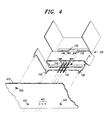
- FIGURE 4 illustrated is an isometric view of the heat sink and component assembly of FIGURE 3 proximate a printed wiring board.
- the component/heat sink assembly 300 may be readily located on a printed wiring board 410 with the alignment tangs 150 extending into corresponding alignment apertures 450 and electrical leads 145 aligned with corresponding contact openings 445.
- the relative positions of alignment tangs 150, alignment bosses 130, and component leads 145 cooperate to facilitate assembly of the component/heat sink assembly 300 to the printed wiring board 410.
- a heat sink 100 has been described that eliminates the need for adhesives, spring clamping devices, or hold-down brackets with a secondary mechanical fastener.
- the heat sink 100 is readily manufactured of sheet metal by stamping and forming. Assembling the heat-generating component 140 to the heat sink 100 is easily performed by a technician.
- the electrical component leads 145 and alignment tangs 150 of the component/heat sink assembly 300 readily align with contact openings 445 and alignment apertures 450, respectively, formed in a printed wiring board 410.
Landscapes
- Cooling Or The Like Of Semiconductors Or Solid State Devices (AREA)
- Cooling Or The Like Of Electrical Apparatus (AREA)
- Mounting Components In General For Electric Apparatus (AREA)
Applications Claiming Priority (2)
| Application Number | Priority Date | Filing Date | Title |
|---|---|---|---|
| US09/196,730 US6128191A (en) | 1998-11-20 | 1998-11-20 | Heat sink with integral self-locking clamp |
| US196730 | 1998-11-20 |
Publications (2)
| Publication Number | Publication Date |
|---|---|
| EP1003215A2 true EP1003215A2 (fr) | 2000-05-24 |
| EP1003215A3 EP1003215A3 (fr) | 2003-06-04 |
Family
ID=22726613
Family Applications (1)
| Application Number | Title | Priority Date | Filing Date |
|---|---|---|---|
| EP99308907A Withdrawn EP1003215A3 (fr) | 1998-11-20 | 1999-11-09 | Dissipateur de chaleur avec bride intégrale auto-bloquante |
Country Status (3)
| Country | Link |
|---|---|
| US (1) | US6128191A (fr) |
| EP (1) | EP1003215A3 (fr) |
| JP (1) | JP2000165063A (fr) |
Families Citing this family (6)
| Publication number | Priority date | Publication date | Assignee | Title |
|---|---|---|---|---|
| US6330160B1 (en) * | 2000-07-25 | 2001-12-11 | Lucent Technologies, Inc. | Component retention clip for a heat sink assembly |
| US7017433B2 (en) * | 2001-10-04 | 2006-03-28 | Ssi Technologies, Inc. | Non-contacting sensor multichip module with integral heat-sinks |
| US7151669B2 (en) * | 2003-07-18 | 2006-12-19 | Kechuan K Liu | Configurable heat sink with matrix clipping system |
| US20080019095A1 (en) * | 2006-07-24 | 2008-01-24 | Kechuan Liu | Configurable heat sink with matrix clipping system |
| JP5728865B2 (ja) * | 2010-01-07 | 2015-06-03 | 株式会社リコー | 放熱機構、及び放熱板の支え金具 |
| USD758327S1 (en) * | 2014-09-30 | 2016-06-07 | Valeo Vision | Heat sink for a lighting device module for a vehicle |
Family Cites Families (7)
| Publication number | Priority date | Publication date | Assignee | Title |
|---|---|---|---|---|
| US4054901A (en) * | 1975-10-14 | 1977-10-18 | Thermalloy, Inc. | Index mounting unitary heat sink apparatus with apertured base |
| US4203488A (en) * | 1978-03-01 | 1980-05-20 | Aavid Engineering, Inc. | Self-fastened heat sinks |
| US4235285A (en) * | 1979-10-29 | 1980-11-25 | Aavid Engineering, Inc. | Self-fastened heat sinks |
| US4509839A (en) * | 1983-06-16 | 1985-04-09 | Imc Magnetics Corp. | Heat dissipator for semiconductor devices |
| US4609040A (en) * | 1985-04-01 | 1986-09-02 | Thermalloy Incorporated | Self-securing heat sink |
| US5329436A (en) * | 1993-10-04 | 1994-07-12 | David Chiu | Removable heat sink for xenon arc lamp packages |
| US5611393A (en) * | 1996-02-23 | 1997-03-18 | Wakefield Engineering, Inc. | Clamping heat sink |
-
1998
- 1998-11-20 US US09/196,730 patent/US6128191A/en not_active Expired - Lifetime
-
1999
- 1999-11-09 EP EP99308907A patent/EP1003215A3/fr not_active Withdrawn
- 1999-11-16 JP JP11326031A patent/JP2000165063A/ja active Pending
Also Published As
| Publication number | Publication date |
|---|---|
| US6128191A (en) | 2000-10-03 |
| JP2000165063A (ja) | 2000-06-16 |
| EP1003215A3 (fr) | 2003-06-04 |
Similar Documents
| Publication | Publication Date | Title |
|---|---|---|
| JP5160434B2 (ja) | 多接合部ばねフィンガを有する接地ばねを用いて電子コンポーネントに熱的に接触したヒート・シンクを接地するための方法および装置 | |
| EP3407692B1 (fr) | Module de puissance, ensemble de module de puissance et son procédé d'assemblage | |
| US5991154A (en) | Attachment of electronic device packages to heat sinks | |
| US5077638A (en) | Heat sink for an electric circuit board | |
| US4388967A (en) | Solderable mounting stakes for heat sinks | |
| US7151669B2 (en) | Configurable heat sink with matrix clipping system | |
| US7746648B2 (en) | Modular heat-radiation structure and controller including the structure | |
| EP1037517A2 (fr) | Assemblage refroidisseur pour composants electroniques | |
| EP1709854B1 (fr) | Systeme et procede de mise a niveau automatique des puits thermiques pour dispositifs de plusieurs hauteurs | |
| EP1047293A2 (fr) | Fixation pour radiateur et méthode | |
| US7441590B2 (en) | Radiator for semiconductor | |
| US20020131238A1 (en) | Heat sink | |
| US6128191A (en) | Heat sink with integral self-locking clamp | |
| US6154367A (en) | Heat sink for printed circuit board | |
| WO2002076166A1 (fr) | Drain thermique | |
| EP1113495B1 (fr) | Transistor de puissance monté en surface avec dissipateur thermique | |
| JPH02138797A (ja) | 電子機器 | |
| US6552903B2 (en) | Electronic module | |
| JP2001244669A (ja) | 電子部品の放熱構造 | |
| KR102619975B1 (ko) | 방열 성능이 개선된 인쇄회로기판 | |
| JPH0810230Y2 (ja) | 電気部品と放熱体の取付構造 | |
| EP4557901A1 (fr) | Ensemble de dissipation de chaleur pour circuit | |
| JPH06342989A (ja) | パワー素子の固定方法 | |
| JP2002184919A (ja) | 半導体パッケージ及びその取付方法 | |
| JP2504590B2 (ja) | 空気調和機の室外ユニット用電装品取付け構造 |
Legal Events
| Date | Code | Title | Description |
|---|---|---|---|
| PUAI | Public reference made under article 153(3) epc to a published international application that has entered the european phase |
Free format text: ORIGINAL CODE: 0009012 |
|
| AK | Designated contracting states |
Kind code of ref document: A2 Designated state(s): AT BE CH CY DE DK ES FI FR GB GR IE IT LI LU MC NL PT SE |
|
| AX | Request for extension of the european patent |
Free format text: AL;LT;LV;MK;RO;SI |
|
| PUAL | Search report despatched |
Free format text: ORIGINAL CODE: 0009013 |
|
| AK | Designated contracting states |
Designated state(s): AT BE CH CY DE DK ES FI FR GB GR IE IT LI LU MC NL PT SE |
|
| AX | Request for extension of the european patent |
Extension state: AL LT LV MK RO SI |
|
| AKX | Designation fees paid | ||
| REG | Reference to a national code |
Ref country code: DE Ref legal event code: 8566 |
|
| STAA | Information on the status of an ep patent application or granted ep patent |
Free format text: STATUS: THE APPLICATION IS DEEMED TO BE WITHDRAWN |
|
| 18D | Application deemed to be withdrawn |
Effective date: 20031205 |