EP1003248A2 - Connecteur coaxial modulaire coudé - Google Patents
Connecteur coaxial modulaire coudé Download PDFInfo
- Publication number
- EP1003248A2 EP1003248A2 EP99121954A EP99121954A EP1003248A2 EP 1003248 A2 EP1003248 A2 EP 1003248A2 EP 99121954 A EP99121954 A EP 99121954A EP 99121954 A EP99121954 A EP 99121954A EP 1003248 A2 EP1003248 A2 EP 1003248A2
- Authority
- EP
- European Patent Office
- Prior art keywords
- housing
- connector module
- contact
- inner center
- connecting side
- Prior art date
- Legal status (The legal status is an assumption and is not a legal conclusion. Google has not performed a legal analysis and makes no representation as to the accuracy of the status listed.)
- Withdrawn
Links
Images

Classifications
-
- H—ELECTRICITY
- H01—ELECTRIC ELEMENTS
- H01R—ELECTRICALLY-CONDUCTIVE CONNECTIONS; STRUCTURAL ASSOCIATIONS OF A PLURALITY OF MUTUALLY-INSULATED ELECTRICAL CONNECTING ELEMENTS; COUPLING DEVICES; CURRENT COLLECTORS
- H01R35/00—Flexible or turnable line connectors, i.e. the rotation angle being limited
-
- H—ELECTRICITY
- H01—ELECTRIC ELEMENTS
- H01R—ELECTRICALLY-CONDUCTIVE CONNECTIONS; STRUCTURAL ASSOCIATIONS OF A PLURALITY OF MUTUALLY-INSULATED ELECTRICAL CONNECTING ELEMENTS; COUPLING DEVICES; CURRENT COLLECTORS
- H01R24/00—Two-part coupling devices, or either of their cooperating parts, characterised by their overall structure
- H01R24/38—Two-part coupling devices, or either of their cooperating parts, characterised by their overall structure having concentrically or coaxially arranged contacts
- H01R24/40—Two-part coupling devices, or either of their cooperating parts, characterised by their overall structure having concentrically or coaxially arranged contacts specially adapted for high frequency
- H01R24/50—Two-part coupling devices, or either of their cooperating parts, characterised by their overall structure having concentrically or coaxially arranged contacts specially adapted for high frequency mounted on a PCB [Printed Circuit Board]
-
- H—ELECTRICITY
- H01—ELECTRIC ELEMENTS
- H01R—ELECTRICALLY-CONDUCTIVE CONNECTIONS; STRUCTURAL ASSOCIATIONS OF A PLURALITY OF MUTUALLY-INSULATED ELECTRICAL CONNECTING ELEMENTS; COUPLING DEVICES; CURRENT COLLECTORS
- H01R24/00—Two-part coupling devices, or either of their cooperating parts, characterised by their overall structure
- H01R24/38—Two-part coupling devices, or either of their cooperating parts, characterised by their overall structure having concentrically or coaxially arranged contacts
- H01R24/40—Two-part coupling devices, or either of their cooperating parts, characterised by their overall structure having concentrically or coaxially arranged contacts specially adapted for high frequency
- H01R24/54—Intermediate parts, e.g. adapters, splitters or elbows
- H01R24/542—Adapters
-
- H—ELECTRICITY
- H01—ELECTRIC ELEMENTS
- H01R—ELECTRICALLY-CONDUCTIVE CONNECTIONS; STRUCTURAL ASSOCIATIONS OF A PLURALITY OF MUTUALLY-INSULATED ELECTRICAL CONNECTING ELEMENTS; COUPLING DEVICES; CURRENT COLLECTORS
- H01R2103/00—Two poles
Definitions
- the present invention relates to an angled coaxial connector module for mounting to a circuit board. More particularly, the invention relates to such an angled coaxial connector module which demonstrates relatively high electrical efficiency and which can be manufactured at relatively low cost.
- Coaxial connector modules are known in the prior art, as shown for example by U.S. Patent No. 5,169,343. As seen in such patent, coaxial connector modules are employed to electrically connect high frequency signals to a circuit on a circuit board.
- prior art coaxial connector modules includes contact elements with multiple internal connections within a housing. Such internal connections resulted in decreased electrical efficiency, increased parasitic effects, and increased construction costs.
- These prior devices also included relatively complex housing constructions in order to separately channel multiple high frequency signals and shields, thereby resulting in increased construction and materials costs.
- the center contact of each contact element includes two pieces, each inserted from a respective housing face into a channel, where the two pieces are soldered or welded together inside the housing, and where the channel is then filled with an insulating material.
- an insertion and assembly process can be cumbersome and prone to error.
- the quality of the joint between the two pieces can be suspect, resulting in electrical inefficiencies that can include unwanted resistive, capacitive, and/or inductive characteristics that might interfere with high frequency signals.
- the housing includes a block of metal surrounding the insulation and acting as a shield. The use of a block of metal necessarily includes considerable time and expense in milling and drilling to form the required channels therein.
- the present invention satisfies the aforementioned needs by providing an angled coaxial connector module for being mounted to a circuit board.
- the connector module has a housing with a contact side for mating with a corresponding connector and a connecting side for mounting the connector module to the circuit board.
- the housing is constructed of an electrically insulating material.
- At least one electrical contact element extends through the housing between the contact side and the connecting side.
- the contact element has an electrically conductive inner center contact, an electrically conductive outer shielding tube surrounding the inner center contact at least within the housing, and an insulating member surrounding the inner center contact at least within the housing and electrically isolating the inner center contact and the outer shielding tube.
- the inner center contact and the outer shielding tube each have a corresponding bent portion within the housing such that the contact side of the housing is at an angle with respect to the connecting side of the housing.
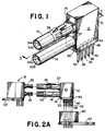
- the connector module has a housing 12 and at least one electrical contact element 14 (two are shown).
- the housing 12 has a contact side 16 for mating connector module 10 with a corresponding connector 18 and a connecting side 20 for mounting connector module 10 to a printed circuit board 22 (shown in Figs. 2A and 2B).
- the housing 12 is constructed of an electrically insulating material such as a plastic or elastomeric material. It is noted that other electrical insulating materials may be employed without departing from the spirit and scope of the present invention.
- the connector module 10 has two electrical contact elements 14. It is noted that any other number of electrical contact elements 14 may be employed in the connector module 10 without departing from the spirit and scope of the present invention. Of course, physical constraints incumbent in the dimensions of any given housing 12 and contact element 14 will as a practical matter limit the number of such contact elements 14 that will fit into such housing 12.
- the connector module 10 has a plurality of electrical contact elements 14, such elements 14 are arranged in rows and columns on the contact side 18 of the housing.
- the connector module 10 shown has a pair of electrical contact elements 14 arranged in one column and two rows.
- the contact elements 14 may be arranged in staggered rows.
- each contact element 14 is shown to extend through the housing 12 between the contact side 16 and the connecting side 20.
- the contact elements 14 extend through the housing 12 to the connecting side 20 while maintaining the aforementioned row and column arrangement, although other internal arrangements may be employed without departing from the spirit and scope of the present invention.
- Each contact element 14 has an electrically conductive inner center contact 24 and an electrically conductive outer shielding tube 26 surrounding the inner center contact 24 at least within the housing 12.
- each of the inner center contact 24 and the outer shielding tube 26 is formed as a substantially unitary body (i.e., as one piece).
- each element 24, 26 may be molded, or may be appropriately rolled from a sheet of material.
- each of the inner center contact 24 and the outer shielding tube 26 is constructed of trial or another similar electrically conductive material.
- other electrically conductive materials may be employed without departing from the spirit and scope of the present invention.
- each contact element 14 also includes an insulating member 28 that surrounds the inner center contact 24 at least within the housing 12 and that electrically isolates the inner center contact 24 and the outer shielding tube 26.
- the insulating member 28 is constructed of PTFE (i.e., TEFLON) or another similar plastic or elastomeric material, although other insulating materials may be employed in connection with the insulating member 28 without departing from the spirit and scope of the present invention.
- each of the inner center contact 24 and the outer shielding tube 26 have corresponding bent portions 30 within the housing 12.
- the contact side 16 of the housing 14 is at a substantially right angle with respect to the connecting side 20 of the housing side 14.
- the right angle connector module 10 may be mounted on the circuit board 22 and coupled with the corresponding right angle connector 18, with the net result being that the circuit board 22 and circuit board 23 occupy substantially parallel planes.
- the circuit boards 22 and 23 may be desirable that the circuit boards 22 and 23 not occupy parallel planes.
- the contact side 16 of the housing 14 may be at practically any angle with respect to the connecting side 20 of the housing side 14 without departing from the spirit and scope of the present invention.
- each contact element 14 is constructed to be a substantially linear (i.e., straight), then is bent in an appropriate area by an appropriate mechanical device or assembly, and then is incorporated within or molded within the connector module 10.
- an appropriate mechanical device or assembly is known, and therefore need not be further described here.
- the insulating member 28 comprises a series of discrete insulating beads 32, at least within the housing 12, where each bead 32 is relatively flexible. As shown, the beads 32 are necessarily positioned within the outer shielding tube 26 and surrounding the inner center contact 24. Preferably, each bead has a relatively short axial length as compared with the length of the contact element 14.
- Each insulating bead 32 is appropriately positioned adjacent neighboring insulating beads 32 such that electrical isolation between the inner center contact 24 and the outer shielding tube 26 is maintained, even at the bent portions 30.
- the flexibility of the insulating beads 32, especially in the vicinity of the bent portion 30, should prevent bead disintegration that could potentially occur as a result of bending the electrical contact element 14 including the beads 32.
- each contact element 14, including the inner center contact 24, the insulating member 28, and the outer shielding tube 26, preferably extends outside the housing 12 from the contact side 16 a predetermined distance which is appropriate for interconnection to the corresponding connector 18 (as seen Fig. 2A).
- each inner center contact 24 terminates in a female member 34a surrounded by an insulating collar 33
- each outer shielding tube 26 terminates at a female member 34b coaxial with and exterior to the female member 34a and the collar 33.
- a corresponding male-male termination 35 on the corresponding connector 18 (Fig. 2A) can be received by each electrical contact element 14 of the connector module 10.
- each electrical contact element 14 may terminate at the extension from the contact side 16 in any appropriate manner without departing from the spirit and scope of the present invention.
- each termination 35 on the corresponding connector 18 it may be necessary that the outer shielding tube 26 of each contact element 14 have a relatively large first cross-sectional diameter D1 at the extension from the contact side 16 outside the housing 12, as illustrated in Figs. 3B.
- D1 may not be necessary and may in fact be too large inside the housing 12.
- the outer shielding tube 26 it is preferable that the outer shielding tube 26 have a relatively small second cross-sectional diameter D2 inside the housing 12, as also illustrated in Fig. 3B.
- the relative diameters D1, D2 of the outer shielding tube 26 both inside and outside the housing 12, can and will vary.
- the connector module 10 may also include a retention clip 36 to retain the connector module 10 in a coupled relationship with the corresponding connector 18 (Fig. 2A).
- the retention clip 36 is positioned or formed on the outer shielding tube 26 of one of the contact elements 14 outside the housing 12.
- Retention clip 36 includes a springed tab or the like that securely retainingly engages a receiving recess (not shown) in the corresponding connector 18 to lock the connector module 10 in a mated position therewith.
- the corresponding connector 18 includes a shroud extending out from the main body thereof (not shown) to form a cavity within which the terminations 35 reside.
- the previously mentioned receiving recess is formed in such shroud.
- the shroud may also have various other slots, apertures, etc. (not shown) for receiving corresponding projections, keys, etc. associated with the connector module 10.
- One such key 37 can be seen in the drawings as a shaped radial extension on one of the outer shielding tubes 26 adjacent the contact side 16 of the housing 12.
- the connector module 10 and the corresponding connector 18 would form a matched set based on such projections, keys, apertures, slots, etc.
- the housing 12 is preferably formed by pre-positioning each contact element 14 and then molding the housing material (e.g., plastic) over the pre-positioned elements to form a plastic over-molded housing 12.
- the plastic over-molded housing 12 provides structural support to the contact elements 14. Methods for performing plastic over-molding are known and therefore need not be further described here.
- the molded plastic that forms the housing 12 has an appropriate dielectric constant such that stray capacitive coupling between each of the contact elements 14 is minimized, thereby minimizing cross-talk between the contact elements 14.
- a first releasable insertion pin 38 is electrically coupled to the inner center contact 24 of each contact element 14 at the connecting side 20 of the housing 12.
- the first pin 38 preferably extends coaxially from the inner center contact 24 outside the housing 12 a predetermined distance.
- Such first pin 38 can either be releasably coupled to a complimentary pin-receiving receptacle block or pin receiver 40 (shown in Fig. 2A) or inserted into pre-formed bores in a circuit board.
- the pin receiver 40 is securely mounted to the circuit board 22.
- the connector module 10 and each inner center contact 24 thereof can be releasably electrically and mechanically coupled to the circuit board 22 by way of each first pin 38.
- each outer shielding tube 26 should also be releasably electrically coupled to circuit board 22. It is preferable that at least one second insertion pin 42 be electrically coupled to the outer shielding tube 26 of each contact element 14 at the connecting side 20 of the housing 12. As with each first pin 38, each second pin 42 also extends from the housing 12 a predetermined distance such that each second pin 42 can be releasably coupled to either pin receiver 40 or inserted into bores formed in a circuit board.
- the connector module 10 has a shield plate 44 positioned on the connecting side 20 of the housing 12.
- shield plate 44 is mechanically coupled to the housing 12 during the aforementioned plastic over-molding of the housing 12.
- the shield plate 44 abuts and is electrically coupled to the outer shielding tube 26 of each contact element 14.
- the outer shielding tube 26 of each contact element 14 is electrically coupled to one another by way of the shield plate 44.
- the shield plate includes apertures through which each first pin 38 may be inserted and coupled to a respective inner center contact 24. The shielding plate 44 should not violate the electrical isolation of each inner center contact 24 and any outer shielding tube 26.
- each second pin 42 be electrically coupled to the shield plate 44. Since the outer shielding tubes 26 are electrically coupled to one another by way of the shield plate 44, the number of second pins 42 need not necessarily correspond to the number of contact elements 14. Instead, and as is shown in Figs. 1, 2A, and 3A the number of second pins 42 may differ. The exact number of second pins 42 employed will vary based upon many considerations, all without departing from the spirit and scope of the present invention.
- each first pin 38 is a separate element from its corresponding inner center contact 24, and is therefore mechanically coupled thereto.
- each second pin 42 is a separate element from the shield plate 44, and is therefore mechanically coupled thereto by any suitable means.
- the mechanical coupling is achieved by micro-butt-welding such that unwanted resistance, capacitance, inductance, and other electrical characteristics are avoided or at least minimized.
- Each first pin 38 and its corresponding inner center contact 24 may be formed as a substantially unitary body, and second pins 42 and shield plate 44 may likewise be formed as a substantially unitary body, without departing from the spirit and scope of the present invention.
- each of the first and second insertion pins 38, 42 includes an expanded mid-portion 46 in order to maintain a tight interference fit when the pin is inserted in either receiver 40 or bores in a circuit board.
- the particular design and construction of the first and second insertion pins 38, 42 may differ without departing from the spirit and scope of the present invention.
- pins 48 are electrically coupled to the shield plate 44 and extend in substantially the same direction and distance as the extensions of the inner center contacts 24 from the housing 12. Pins 48 can also be employed to secure the connector module 10 directly to circuit board 22.
- the pins 48 are micro-butt-welded to the shield plate 44. Pins 48 and the shield plate 44 may also be formed as a substantially unitary body, without departing from the spirit and scope of the present invention.
- the present invention comprises a new and useful angled coaxial connector module.
- the contact elements of the connector module do not have internal connections that would decrease electrical efficiency.
- the connector module may be constructed in a cost-effective manner from relatively inexpensive materials such that a relatively high state electrical efficiency is maintained. Changes could be made to the embodiments described above without departing from the broad inventive concepts thereof. It is understood, therefore, that this invention is not limited to the particular embodiments disclosed, but it is intended to cover modifications within the spirit and scope of the present invention as defined by the appended claims.
Landscapes
- Coupling Device And Connection With Printed Circuit (AREA)
Applications Claiming Priority (2)
| Application Number | Priority Date | Filing Date | Title |
|---|---|---|---|
| US09/196,926 US6305947B1 (en) | 1998-11-19 | 1998-11-19 | Angled coaxial connector module |
| US196926 | 1998-11-19 |
Publications (2)
| Publication Number | Publication Date |
|---|---|
| EP1003248A2 true EP1003248A2 (fr) | 2000-05-24 |
| EP1003248A3 EP1003248A3 (fr) | 2001-04-04 |
Family
ID=22727321
Family Applications (1)
| Application Number | Title | Priority Date | Filing Date |
|---|---|---|---|
| EP99121954A Withdrawn EP1003248A3 (fr) | 1998-11-19 | 1999-11-09 | Connecteur coaxial modulaire coudé |
Country Status (7)
| Country | Link |
|---|---|
| US (1) | US6305947B1 (fr) |
| EP (1) | EP1003248A3 (fr) |
| JP (1) | JP2000260538A (fr) |
| KR (1) | KR20000035540A (fr) |
| CA (1) | CA2289140A1 (fr) |
| SG (1) | SG82029A1 (fr) |
| TW (1) | TW520797U (fr) |
Cited By (3)
| Publication number | Priority date | Publication date | Assignee | Title |
|---|---|---|---|---|
| EP1187268A3 (fr) * | 2000-08-30 | 2002-09-25 | Molex Incorporated | Connecteur coaxial modulaire et son procédé de fabrication |
| EP1566862A1 (fr) * | 2004-02-20 | 2005-08-24 | Osram Sylvania Inc. | Connecteur à angle droit |
| EP3281258A1 (fr) * | 2015-04-10 | 2018-02-14 | Robert Bosch GmbH | Appareil de commande électronique |
Families Citing this family (30)
| Publication number | Priority date | Publication date | Assignee | Title |
|---|---|---|---|---|
| US6979202B2 (en) | 2001-01-12 | 2005-12-27 | Litton Systems, Inc. | High-speed electrical connector |
| US6910897B2 (en) | 2001-01-12 | 2005-06-28 | Litton Systems, Inc. | Interconnection system |
| US6843657B2 (en) | 2001-01-12 | 2005-01-18 | Litton Systems Inc. | High speed, high density interconnect system for differential and single-ended transmission applications |
| WO2003008751A1 (fr) | 2001-07-16 | 2003-01-30 | Hunter Douglas Industries B.V. | Fermeture de type volet pour ouvertures architecturales |
| US6431915B1 (en) * | 2001-09-10 | 2002-08-13 | Hon Hai Precision Ind. Co., Ltd. | RF cable connector assembly for preventing mis-mating |
| FR2839815B1 (fr) * | 2002-05-15 | 2004-06-25 | Positronic Ind | Procede de scellage de contacts de connecteur de traversee de cloison de type coaxiaux, contact coaxial adapte et connecteur ainsi obtenu |
| US6905367B2 (en) | 2002-07-16 | 2005-06-14 | Silicon Bandwidth, Inc. | Modular coaxial electrical interconnect system having a modular frame and electrically shielded signal paths and a method of making the same |
| TWD105679S1 (zh) | 2002-09-25 | 2005-07-21 | 松下電工股份有限公司 | 光配線用連接器 |
| CA102539S (en) | 2002-09-25 | 2004-03-22 | Matsushita Electric Works Ltd | Connector for optical wiring |
| JP3848300B2 (ja) * | 2003-05-28 | 2006-11-22 | 株式会社アドバンテスト | コネクタ |
| US6776621B1 (en) | 2003-08-27 | 2004-08-17 | Itt Manufacturing Enterprises, Inc. | Board mounted coax connector assembly |
| US6932616B1 (en) * | 2004-05-12 | 2005-08-23 | Osram Sylvania Inc. | Connector with integral EMI shield |
| US7540771B2 (en) * | 2004-07-10 | 2009-06-02 | Gigalane Co., Ltd | Right angle coaxial connector mountable on PCB |
| US7264499B2 (en) * | 2004-10-14 | 2007-09-04 | Pent Technologies, Inc. | Power entry assembly for an electrical distribution system |
| US7121883B1 (en) * | 2005-06-06 | 2006-10-17 | John Mezzalingua Associates, Inc. | Coax connector having steering insulator |
| US20080096426A1 (en) * | 2006-10-20 | 2008-04-24 | Z-Com, Inc. | Coupling device for testing antenna |
| KR100880713B1 (ko) * | 2007-01-09 | 2009-02-02 | (주)기가레인 | 기판 실장형의 직각형 동축 코넥터 |
| US7473137B2 (en) * | 2007-03-30 | 2009-01-06 | Intel Corporation | Right-angle coaxial connector |
| US7699617B2 (en) * | 2007-10-08 | 2010-04-20 | Winchester Electronics Corporation | Modular interconnect apparatus |
| JP5155700B2 (ja) * | 2008-03-11 | 2013-03-06 | 富士通コンポーネント株式会社 | コネクタ |
| JP2010033836A (ja) * | 2008-07-28 | 2010-02-12 | Fujitsu Ltd | コネクタ及びコネクタ用伝送配線 |
| KR101054538B1 (ko) * | 2009-04-06 | 2011-08-04 | 엘에스엠트론 주식회사 | 전자파 차폐 커넥터 |
| US8096834B2 (en) * | 2009-08-12 | 2012-01-17 | Giga-Byte Technology Co., Ltd. | Connector with electromagnetic conduction mechanism |
| GB201113338D0 (en) * | 2011-08-03 | 2011-09-14 | Rota Eng Ltd | Connector |
| DE102012204002B4 (de) * | 2012-03-14 | 2024-11-21 | Zf Friedrichshafen Ag | Steckervorrichtung für eine Leiterplatte eines Steuergeräts für ein Fahrzeuggetriebe, Steuersystem für ein Fahrzeuggetriebe und Verfahren zum Montieren eines Steuersystems für ein Fahrzeuggetriebe |
| KR101476654B1 (ko) * | 2013-04-09 | 2014-12-26 | (주)옥성 | 고주파용 동축 커넥터 제조장치와 이를 이용한 고주파용 동축 커넥터 제조방법 및 이 방법에 의해 제조된 고주파용 동축 커넥터 |
| DE202013006662U1 (de) * | 2013-07-24 | 2013-08-08 | Rosenberger Hochfrequenztechnik Gmbh & Co. Kg | System aus Leiterplatte und rohrförmigem Mantel |
| US9762001B2 (en) * | 2016-02-01 | 2017-09-12 | Delphi Technologies, Inc. | Right angled coaxial electrical connector and methods for verifying proper assembly thereof |
| EP3930104A1 (fr) * | 2020-06-24 | 2021-12-29 | Rosenberger Hochfrequenztechnik GmbH & Co. KG | Module de câbles extérieurs, connecteur enfichable électrique et agencement de raccordement électrique |
| CN114640000A (zh) * | 2022-01-25 | 2022-06-17 | 富加宜连接器(东莞)有限公司 | 一种同轴高速连接器 |
Family Cites Families (20)
| Publication number | Priority date | Publication date | Assignee | Title |
|---|---|---|---|---|
| US3201722A (en) | 1963-10-17 | 1965-08-17 | Charles B May | Transmission line adapter for connecting coaxial and strip transmission lines at right angles |
| US4842528A (en) * | 1987-03-27 | 1989-06-27 | Amp Incorporated | Solder post retention means |
| US5060373A (en) | 1989-08-22 | 1991-10-29 | The Phoenix Company Of Chicago, Inc. | Methods for making coaxial connectors |
| GB9019540D0 (en) | 1990-09-07 | 1990-10-24 | Amp Great Britain | Coaxial electrical connectors and their manufacture |
| US5169343A (en) | 1990-11-29 | 1992-12-08 | E. I. Du Pont De Nemours And Company | Coax connector module |
| US5088937A (en) | 1991-04-19 | 1992-02-18 | Amp Incorporated | Right angle coaxial jack connector |
| US5161991A (en) * | 1991-07-31 | 1992-11-10 | Sun Microsystems, Inc. | Electrostatic discharge plate for an electrical connector |
| FR2685553A1 (fr) | 1991-12-18 | 1993-06-25 | Radiall Sa | Element de connecteur coaxial coude apte a etre fixe a une carte imprimee. |
| NL9202302A (nl) | 1992-12-31 | 1994-07-18 | Du Pont Nederland | Koaxiaal interkonnektiesysteem. |
| FR2702095B1 (fr) | 1993-02-26 | 1995-04-14 | Radiall Sa | Elément coudé de connecteur coaxial apte à être fixé à une carte imprimée. |
| US5397241A (en) | 1993-10-25 | 1995-03-14 | At&T Corp. | High density electrical connector |
| FR2726128B1 (fr) | 1994-10-19 | 1996-12-27 | Radiall Sa | Connecteur electrique multivoie sans barriere electromagnetique entre les voies |
| DE4438872C1 (de) | 1994-11-03 | 1995-12-07 | Harting Elektronik Gmbh | Koaxialer Winkelverbinder zur Montage auf einer Leiterplatte |
| US5641294A (en) | 1995-05-31 | 1997-06-24 | Northern Telecom Limited | Backplane assembly including coaxial connectors |
| US5842872A (en) * | 1995-06-30 | 1998-12-01 | The Whitaker Corporation | Modular right angle board mountable coaxial connector |
| WO1997002629A1 (fr) | 1995-06-30 | 1997-01-23 | The Whitaker Corporation | Connecteur coaxial a angle droit se montant sur un panneau modulaire |
| US5645454A (en) | 1995-11-24 | 1997-07-08 | Itt Corporation | Right angle coaxial connector and method of assembling same |
| FR2746971B1 (fr) | 1996-04-01 | 1998-04-30 | Framatome Connectors France | Connecteur blinde miniature a tiges de contact coudees |
| WO1997040554A1 (fr) | 1996-04-25 | 1997-10-30 | The Whitaker Corporation | Ensemble contact pour connecteur coaxial |
| US5718606A (en) | 1996-10-30 | 1998-02-17 | Component Equipment Company, Inc. | Electrical connector between a pair of printed circuit boards |
-
1998
- 1998-11-19 US US09/196,926 patent/US6305947B1/en not_active Expired - Fee Related
-
1999
- 1999-11-01 TW TW088218583U patent/TW520797U/zh unknown
- 1999-11-02 SG SG9905439A patent/SG82029A1/en unknown
- 1999-11-08 CA CA002289140A patent/CA2289140A1/fr not_active Abandoned
- 1999-11-09 EP EP99121954A patent/EP1003248A3/fr not_active Withdrawn
- 1999-11-18 KR KR1019990051190A patent/KR20000035540A/ko not_active Withdrawn
- 1999-11-19 JP JP11329788A patent/JP2000260538A/ja active Pending
Cited By (3)
| Publication number | Priority date | Publication date | Assignee | Title |
|---|---|---|---|---|
| EP1187268A3 (fr) * | 2000-08-30 | 2002-09-25 | Molex Incorporated | Connecteur coaxial modulaire et son procédé de fabrication |
| EP1566862A1 (fr) * | 2004-02-20 | 2005-08-24 | Osram Sylvania Inc. | Connecteur à angle droit |
| EP3281258A1 (fr) * | 2015-04-10 | 2018-02-14 | Robert Bosch GmbH | Appareil de commande électronique |
Also Published As
| Publication number | Publication date |
|---|---|
| EP1003248A3 (fr) | 2001-04-04 |
| JP2000260538A (ja) | 2000-09-22 |
| US6305947B1 (en) | 2001-10-23 |
| CA2289140A1 (fr) | 2000-05-19 |
| TW520797U (en) | 2003-02-11 |
| SG82029A1 (en) | 2001-07-24 |
| KR20000035540A (en) | 2000-06-26 |
Similar Documents
| Publication | Publication Date | Title |
|---|---|---|
| US6305947B1 (en) | Angled coaxial connector module | |
| EP0446980B2 (fr) | Ensemble de connexion pour cartes de circuits imprimés | |
| US4674809A (en) | Filtered triax connector | |
| RU2089978C1 (ru) | Многоконтактный экранированный соединитель с общим заземлением | |
| EP0486298B1 (fr) | Connecteur à multicontact pour transmission des signaux | |
| US5664968A (en) | Connector assembly with shielded modules | |
| US5620340A (en) | Connector with improved shielding | |
| EP0620616B1 (fr) | Connecteur pour câble coaxial et/ou câble biaxial | |
| EP2755282B1 (fr) | Adaptateur | |
| US6071127A (en) | HF coaxial connector having a plug module and a socket module | |
| CN102282727B (zh) | Rf用插头式连接器、rf用插座式连接器以及rf用连接器 | |
| US9312640B2 (en) | Shielded connector assembly | |
| EP1018784A1 (fr) | Connecteur blindé et procédé de fabrication | |
| US5842887A (en) | Connector with improved shielding | |
| EP0999611B1 (fr) | Connecteur multi-coaxial comprenant une cage métallique connectée aux conducteurs extérieurs de plusieurs câbles coaxiaux | |
| JPH08288019A (ja) | 少なくとも1の同軸あるいは2軸端子を有する選択的に金属化されたコネクタ | |
| CN104466538B (zh) | 电连接器 | |
| EP1485973A2 (fr) | Embase de connecteur et ecran de protection | |
| CA2144704A1 (fr) | Connecteur combine | |
| EP3411928B1 (fr) | Connecteur enfichable à séparation galvanique intégrée et élément de blindage | |
| WO1995016292A1 (fr) | Raccord coaxial a regulation d'impedance | |
| EP0677215B1 (fr) | Connecteur a blindage ameliore | |
| US6056559A (en) | Punched sheet coax header | |
| US5213521A (en) | High frequency electrical connector assembly | |
| CN102938524B (zh) | 连接器装置 |
Legal Events
| Date | Code | Title | Description |
|---|---|---|---|
| PUAI | Public reference made under article 153(3) epc to a published international application that has entered the european phase |
Free format text: ORIGINAL CODE: 0009012 |
|
| AK | Designated contracting states |
Kind code of ref document: A2 Designated state(s): AT BE CH CY DE DK ES FI FR GB GR IE IT LI LU MC NL PT SE |
|
| AX | Request for extension of the european patent |
Free format text: AL;LT;LV;MK;RO;SI |
|
| PUAL | Search report despatched |
Free format text: ORIGINAL CODE: 0009013 |
|
| AK | Designated contracting states |
Kind code of ref document: A3 Designated state(s): AT BE CH CY DE DK ES FI FR GB GR IE IT LI LU MC NL PT SE |
|
| AX | Request for extension of the european patent |
Free format text: AL;LT;LV;MK;RO;SI |
|
| 17P | Request for examination filed |
Effective date: 20010808 |
|
| AKX | Designation fees paid |
Free format text: AT BE CH CY DE DK ES FI FR GB GR IE IT LI LU MC NL PT SE |
|
| STAA | Information on the status of an ep patent application or granted ep patent |
Free format text: STATUS: THE APPLICATION IS DEEMED TO BE WITHDRAWN |
|
| 18D | Application deemed to be withdrawn |
Effective date: 20040602 |