EP1003285B1 - Lautheitsfilter - Google Patents
Lautheitsfilter Download PDFInfo
- Publication number
- EP1003285B1 EP1003285B1 EP19990122780 EP99122780A EP1003285B1 EP 1003285 B1 EP1003285 B1 EP 1003285B1 EP 19990122780 EP19990122780 EP 19990122780 EP 99122780 A EP99122780 A EP 99122780A EP 1003285 B1 EP1003285 B1 EP 1003285B1
- Authority
- EP
- European Patent Office
- Prior art keywords
- synthesizer
- pass filter
- resistor
- output
- low
- Prior art date
- Legal status (The legal status is an assumption and is not a legal conclusion. Google has not performed a legal analysis and makes no representation as to the accuracy of the status listed.)
- Expired - Lifetime
Links
- 230000002194 synthesizing effect Effects 0.000 claims description 10
- 239000003990 capacitor Substances 0.000 description 9
- 238000010586 diagram Methods 0.000 description 5
- 230000005236 sound signal Effects 0.000 description 1
Images

Classifications
-
- H—ELECTRICITY
- H03—ELECTRONIC CIRCUITRY
- H03G—CONTROL OF AMPLIFICATION
- H03G5/00—Tone control or bandwidth control in amplifiers
- H03G5/16—Automatic control
- H03G5/165—Equalizers; Volume or gain control in limited frequency bands
Definitions
- the present invention relates to a loudness device used in an audio signal processing system.
- a conventional loudness device is composed of a series connection of capacitors 50 and 51 and a variable resistor 52 which are connected in parallel for an input.
- the connecting point between the capacitors 50 and 51 and the middle point in resistance of the variable resistor 52 are connected to each other.
- An output is obtained from a sliding piece of the variable resistor 52.
- Fig. 5 is a graph showing the characteristic when the sliding piece of the variable resistor 52 in the loudness device as shown in Fig. 4 is shifted.
- line A indicates the characteristic when the sliding piece has been shifted to the maximum toward the input terminal. In this case, an input signal is outputted as it is.
- both low frequency and high frequency ranges attenuate.
- the intermediate frequency range attenuates more greatly.
- the intermediate frequency range attenuates further more greatly than both low frequency and high frequency ranges.
- the characteristic in each of both low frequency and high frequency ranges is uniquely defined according to setting the attenuation degree in the intermediate range. Therefore, a user cannot control the loudness to the most preferable characteristic.
- JP 02 222207 describes a hearing sense compensation device having fixed cut-off frequencies. It comprises a low pass filter and a high pass filter in order to derive a low frequency band and a high frequency band of the input signal, a first synthesizer having a fixed synthesizing rate to mix the output signals from the low and high pass filter, and a second synthesizer for synthesizing the input signal and the output of the first synthesizer at a variable synthesizing rate.
- An object of the present invention is to provide a loudness device which can vary the attenuation degree of an intermediate frequency band, cutoff frequency of a low frequency pass-band, cutoff frequency of a high frequency pass-band, and attenuation degree of the high frequency pass-band.
- a loudness device comprising: a low-pass filter (LPF) which has a variable cut-off frequency and passes a low frequency band of an input signal; a high-pass filter (HPF) which has a variable cut-off frequency and passes a high frequency band of the input signal; a first synthesizer for synthesizing output signals from the LPF and HPF at a variable synthesizing rate to provide a first synthesized output; and a second synthesizer for synthesizing the input signal and an output from the first synthesizer at a variable synthesizing rate to provide a second synthesized output.
- LPF low-pass filter
- HPF high-pass filter
- the loudness device can vary the attenuation degree of an intermediate frequency band, cutoff frequency of a low-pass frequency band, cutoff frequency of a high-pass frequency band, and attenuation degree of the high -pass frequency band.
- the second synthesizer is a sliding resistor having end terminals to which the input signal and the output signal from the first synthesizer are supplied, respectively and a sliding terminal from which the synthesized output is produced.
- the attenuation degree of the intermediate frequency band can be easily varied by shifting the position of the sliding terminal.
- the first synthesizer includes an operational amplifier, a first fixed resistor through which the output signal from the LPF is connected, a variable resistor through which the output signal from the HPF is connected, and a second fixed resistor having a resistance equal to that of the first fixed resistor, through which an output from the operational amplifier is fed back to an input thereof.
- the attenuation degree of the high-pass frequency band can be easily varied by varying the resistance of the variable resistor.
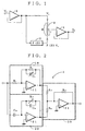
- Fig. 1 is a schematic circuit diagram of an embodiment of a loudness device according to the present invention.
- Fig. 2 is a concrete circuit diagram of a filter block in the embodiment of the loudness device.
- reference numeral 1 denotes a buffer amplifier; 2 a filter block; 3 a second synthesizer for synthesizing an input signal and a filter block output; and 4 a buffer amplifier.
- the second synthesizer 3 includes a sliding resistor, to both ends of which an input signal (Vi) and an output signal (F(s)Vi) from the filter block 2 are supplied. An output signal is produced from a sliding terminal of the sliding resistor, and supplied to the buffer amplifier 4.
- the filter block 2 as shown in Fig. 2, a low-pass filter (LPF) 10, a high-pass filter (HPF) 20 and a first synthesizer 30.
- LPF low-pass filter
- HPF high-pass filter
- the low-pass filter (LPF) 10 serves as a first order low-pass filter having a time constant of the values of the resistor R1 and capacitor C1.
- the cut-off frequency of the low-pass filter 10 can be varied by the capacitance of the capacitor C1.
- the high-pass filter (LPF) 20 serves as a first order high-pass filter having a time constant of the values of the resistor R2 and capacitor C2.
- the cut-off frequency of the high-pass filter 20 can be varied by varying the resistance of the resistor R2.
- the output from the low-pass filter 10 is supplied to an operational amplifier 31 through a resistor R3, the output from the high-pass filter 20 is also supplied to the operational amplifier 31 through a resistor R4, and the output from the operational amplifier 31 is fed back to the input thereof though a resistor R5 having a resistance equal to that of the resistor R3.
- the low-pass frequency band can be varied by varying the capacitance of the capacitor C1 of the LPF 10 ("A" in Fig. 3)
- the high-pass frequency band can be varied by the resistance of the resistor R2 of the HPF 20 ("B” in Fig. 3)
- the attenuation degree in the high-pass frequency band can be varied by varying the resistance of the resistor R4 ("C” in Fig. 3) of the first synthesizer 30
- the attenuation degree of the intermediate frequency band can be varied by shifting the sliding position ( ⁇ /R) of the sliding terminal of the second synthesizer 3 ("D" in Fig. 3).
Landscapes
- Tone Control, Compression And Expansion, Limiting Amplitude (AREA)
- Circuit For Audible Band Transducer (AREA)
Claims (3)
- Lautstärkevorrichtung mit einstellbarer Frequenzkennlinie, die enthält:dadurch gekennzeichnet, dass:ein Tiefpassfilter (10), das ein Tieffrequenzband eines Eingangssignals durchlässt,ein Hochpassfilter (20), das ein Hochfrequenzband des Eingangssignals durchlässt,einen ersten Synthesizer (30), der die Ausgangssignale von dem Tiefpassfilter (10) und dem Hochpassfilter (20) synthetisiert, undeinen zweiten Synthesizer (3), der das Eingangssignal und das Ausgangssignal von dem ersten Synthesizer (30) synthetisiert, um einen synthetisierten Ausgang zu erzeugen, wobei der zweite Synthesizer (3) so eingerichtet ist, dass er eine veränderliche Dämpfung des Zwischenfrequenzbandes vorsieht;die Grenzfrequenz des Tiefpassfilters (10) und die Grenzfrequenz des Hochpassfilters (20) einstellbar sind,der erste Synthesizer (30) so eingerichtet ist, dass er eine veränderliche Dämpfung des Hochpass-Frequenzbandes vorsieht.
- Lautstärkevorrichtung nach Anspruch 1, wobei der zweite Synthesizer (3) ein Gleitwiderstand ist, der einen Gleitanschluss hat, von dem der synthetisierte Ausgang abgenommen wird, und der Gleitwiderstand an einem Ende mit dem Eingangssignal und am anderen Ende mit dem Ausgangssignal von dem ersten Synthesizer (30) gespeist wird.
- Lautstärkevorrichtung nach Anspruch 1 oder 2, wobei der erste Synthesizer (30) enthält:einen Operationsverstärker (31),einen ersten Festwiderstand, über den das Ausgangssignal von dem Tiefpassfilter (10) geschaltet wird,einen Regelwiderstand, über den das Ausgangssignal von dem Hochpassfilter (20) geschaltet wird, undeinen zweiten Festwiderstand, der einen Widerstandswert hat, der dem des ersten Festwiderstandes gleich ist und über den ein Ausgang von dem Operationsverstärker (31) zu einem Eingang desselben zurückgeführt wird.
Applications Claiming Priority (2)
| Application Number | Priority Date | Filing Date | Title |
|---|---|---|---|
| JP32652998A JP3543929B2 (ja) | 1998-11-17 | 1998-11-17 | ラウドネス装置 |
| JP32652998 | 1998-11-17 |
Publications (3)
| Publication Number | Publication Date |
|---|---|
| EP1003285A2 EP1003285A2 (de) | 2000-05-24 |
| EP1003285A3 EP1003285A3 (de) | 2003-10-08 |
| EP1003285B1 true EP1003285B1 (de) | 2005-08-31 |
Family
ID=18188862
Family Applications (1)
| Application Number | Title | Priority Date | Filing Date |
|---|---|---|---|
| EP19990122780 Expired - Lifetime EP1003285B1 (de) | 1998-11-17 | 1999-11-16 | Lautheitsfilter |
Country Status (3)
| Country | Link |
|---|---|
| EP (1) | EP1003285B1 (de) |
| JP (1) | JP3543929B2 (de) |
| DE (1) | DE69926973T2 (de) |
Family Cites Families (3)
| Publication number | Priority date | Publication date | Assignee | Title |
|---|---|---|---|---|
| JPS6188327U (de) * | 1984-11-14 | 1986-06-09 | ||
| JPH02222207A (ja) * | 1989-02-22 | 1990-09-05 | Matsushita Electric Ind Co Ltd | 聴覚補償装置 |
| JPH02118322U (de) * | 1989-03-08 | 1990-09-21 |
-
1998
- 1998-11-17 JP JP32652998A patent/JP3543929B2/ja not_active Expired - Fee Related
-
1999
- 1999-11-16 EP EP19990122780 patent/EP1003285B1/de not_active Expired - Lifetime
- 1999-11-16 DE DE69926973T patent/DE69926973T2/de not_active Expired - Lifetime
Also Published As
| Publication number | Publication date |
|---|---|
| EP1003285A3 (de) | 2003-10-08 |
| DE69926973D1 (de) | 2005-10-06 |
| EP1003285A2 (de) | 2000-05-24 |
| JP3543929B2 (ja) | 2004-07-21 |
| DE69926973T2 (de) | 2006-03-09 |
| JP2000152373A (ja) | 2000-05-30 |
Similar Documents
| Publication | Publication Date | Title |
|---|---|---|
| US5230022A (en) | Low frequency compensating circuit for audio signals | |
| US4394536A (en) | Sound reproduction device | |
| US4119814A (en) | Hearing aid with adjustable frequency response | |
| US5305388A (en) | Bass compensation circuit for use in sound reproduction device | |
| JPH0683113B2 (ja) | 回線等化回路 | |
| US4797933A (en) | Bass amplifier with high frequency response | |
| CN100539406C (zh) | 音频预放大器和中频带压缩器电路 | |
| EP1003285A2 (de) | Lautheitsfilter | |
| US4326172A (en) | Tunable active high-pass filter | |
| US4331927A (en) | Noninverting amplifier circuit with low input impedance | |
| JP3308352B2 (ja) | 可変遅延回路 | |
| JPS6119189B2 (de) | ||
| US20030090315A1 (en) | All pass filter | |
| SU1312723A2 (ru) | Усилитель низкой частоты | |
| KR830000245B1 (ko) | 주파수 특성 조정장치 | |
| JPH0421385B2 (de) | ||
| JPH0738552B2 (ja) | 周波数等化回路 | |
| SU1185573A1 (ru) | Тонкомпенсированный регул тор громкости | |
| JPS6237567B2 (de) | ||
| JPS6145638Y2 (de) | ||
| SU1543567A1 (ru) | Устройство дл коррекции видеосигнала | |
| JPH0511686B2 (de) | ||
| JPH05267964A (ja) | 帯域ブースト回路 | |
| JPS6123862Y2 (de) | ||
| JPS5951171B2 (ja) | 周波数分割フイルタ |
Legal Events
| Date | Code | Title | Description |
|---|---|---|---|
| PUAI | Public reference made under article 153(3) epc to a published international application that has entered the european phase |
Free format text: ORIGINAL CODE: 0009012 |
|
| 17P | Request for examination filed |
Effective date: 19991116 |
|
| AK | Designated contracting states |
Kind code of ref document: A2 Designated state(s): AT BE CH CY DE DK ES FI FR GB GR IE IT LI LU MC NL PT SE |
|
| AX | Request for extension of the european patent |
Free format text: AL;LT;LV;MK;RO;SI |
|
| PUAL | Search report despatched |
Free format text: ORIGINAL CODE: 0009013 |
|
| AK | Designated contracting states |
Kind code of ref document: A3 Designated state(s): AT BE CH CY DE DK ES FI FR GB GR IE IT LI LU MC NL PT SE |
|
| AX | Request for extension of the european patent |
Extension state: AL LT LV MK RO SI |
|
| 17Q | First examination report despatched |
Effective date: 20040405 |
|
| AKX | Designation fees paid |
Designated state(s): DE IT NL |
|
| GRAP | Despatch of communication of intention to grant a patent |
Free format text: ORIGINAL CODE: EPIDOSNIGR1 |
|
| GRAS | Grant fee paid |
Free format text: ORIGINAL CODE: EPIDOSNIGR3 |
|
| GRAA | (expected) grant |
Free format text: ORIGINAL CODE: 0009210 |
|
| AK | Designated contracting states |
Kind code of ref document: B1 Designated state(s): DE IT NL |
|
| REF | Corresponds to: |
Ref document number: 69926973 Country of ref document: DE Date of ref document: 20051006 Kind code of ref document: P |
|
| PLBE | No opposition filed within time limit |
Free format text: ORIGINAL CODE: 0009261 |
|
| STAA | Information on the status of an ep patent application or granted ep patent |
Free format text: STATUS: NO OPPOSITION FILED WITHIN TIME LIMIT |
|
| 26N | No opposition filed |
Effective date: 20060601 |
|
| PGFP | Annual fee paid to national office [announced via postgrant information from national office to epo] |
Ref country code: DE Payment date: 20091112 Year of fee payment: 11 |
|
| PGFP | Annual fee paid to national office [announced via postgrant information from national office to epo] |
Ref country code: NL Payment date: 20091114 Year of fee payment: 11 |
|
| PGFP | Annual fee paid to national office [announced via postgrant information from national office to epo] |
Ref country code: IT Payment date: 20091117 Year of fee payment: 11 |
|
| REG | Reference to a national code |
Ref country code: NL Ref legal event code: V1 Effective date: 20110601 |
|
| PG25 | Lapsed in a contracting state [announced via postgrant information from national office to epo] |
Ref country code: NL Free format text: LAPSE BECAUSE OF NON-PAYMENT OF DUE FEES Effective date: 20110601 |
|
| REG | Reference to a national code |
Ref country code: DE Ref legal event code: R119 Ref document number: 69926973 Country of ref document: DE Effective date: 20110601 Ref country code: DE Ref legal event code: R119 Ref document number: 69926973 Country of ref document: DE Effective date: 20110531 |
|
| PG25 | Lapsed in a contracting state [announced via postgrant information from national office to epo] |
Ref country code: DE Free format text: LAPSE BECAUSE OF NON-PAYMENT OF DUE FEES Effective date: 20110531 |
|
| PG25 | Lapsed in a contracting state [announced via postgrant information from national office to epo] |
Ref country code: IT Free format text: LAPSE BECAUSE OF NON-PAYMENT OF DUE FEES Effective date: 20101116 |