EP1003285B1 - Filtre d'intensité sonore - Google Patents
Filtre d'intensité sonore Download PDFInfo
- Publication number
- EP1003285B1 EP1003285B1 EP19990122780 EP99122780A EP1003285B1 EP 1003285 B1 EP1003285 B1 EP 1003285B1 EP 19990122780 EP19990122780 EP 19990122780 EP 99122780 A EP99122780 A EP 99122780A EP 1003285 B1 EP1003285 B1 EP 1003285B1
- Authority
- EP
- European Patent Office
- Prior art keywords
- synthesizer
- pass filter
- resistor
- output
- low
- Prior art date
- Legal status (The legal status is an assumption and is not a legal conclusion. Google has not performed a legal analysis and makes no representation as to the accuracy of the status listed.)
- Expired - Lifetime
Links
- 230000002194 synthesizing effect Effects 0.000 claims description 10
- 239000003990 capacitor Substances 0.000 description 9
- 238000010586 diagram Methods 0.000 description 5
- 230000005236 sound signal Effects 0.000 description 1
Images

Classifications
-
- H—ELECTRICITY
- H03—ELECTRONIC CIRCUITRY
- H03G—CONTROL OF AMPLIFICATION
- H03G5/00—Tone control or bandwidth control in amplifiers
- H03G5/16—Automatic control
- H03G5/165—Equalizers; Volume or gain control in limited frequency bands
Definitions
- the present invention relates to a loudness device used in an audio signal processing system.
- a conventional loudness device is composed of a series connection of capacitors 50 and 51 and a variable resistor 52 which are connected in parallel for an input.
- the connecting point between the capacitors 50 and 51 and the middle point in resistance of the variable resistor 52 are connected to each other.
- An output is obtained from a sliding piece of the variable resistor 52.
- Fig. 5 is a graph showing the characteristic when the sliding piece of the variable resistor 52 in the loudness device as shown in Fig. 4 is shifted.
- line A indicates the characteristic when the sliding piece has been shifted to the maximum toward the input terminal. In this case, an input signal is outputted as it is.
- both low frequency and high frequency ranges attenuate.
- the intermediate frequency range attenuates more greatly.
- the intermediate frequency range attenuates further more greatly than both low frequency and high frequency ranges.
- the characteristic in each of both low frequency and high frequency ranges is uniquely defined according to setting the attenuation degree in the intermediate range. Therefore, a user cannot control the loudness to the most preferable characteristic.
- JP 02 222207 describes a hearing sense compensation device having fixed cut-off frequencies. It comprises a low pass filter and a high pass filter in order to derive a low frequency band and a high frequency band of the input signal, a first synthesizer having a fixed synthesizing rate to mix the output signals from the low and high pass filter, and a second synthesizer for synthesizing the input signal and the output of the first synthesizer at a variable synthesizing rate.
- An object of the present invention is to provide a loudness device which can vary the attenuation degree of an intermediate frequency band, cutoff frequency of a low frequency pass-band, cutoff frequency of a high frequency pass-band, and attenuation degree of the high frequency pass-band.
- a loudness device comprising: a low-pass filter (LPF) which has a variable cut-off frequency and passes a low frequency band of an input signal; a high-pass filter (HPF) which has a variable cut-off frequency and passes a high frequency band of the input signal; a first synthesizer for synthesizing output signals from the LPF and HPF at a variable synthesizing rate to provide a first synthesized output; and a second synthesizer for synthesizing the input signal and an output from the first synthesizer at a variable synthesizing rate to provide a second synthesized output.
- LPF low-pass filter
- HPF high-pass filter
- the loudness device can vary the attenuation degree of an intermediate frequency band, cutoff frequency of a low-pass frequency band, cutoff frequency of a high-pass frequency band, and attenuation degree of the high -pass frequency band.
- the second synthesizer is a sliding resistor having end terminals to which the input signal and the output signal from the first synthesizer are supplied, respectively and a sliding terminal from which the synthesized output is produced.
- the attenuation degree of the intermediate frequency band can be easily varied by shifting the position of the sliding terminal.
- the first synthesizer includes an operational amplifier, a first fixed resistor through which the output signal from the LPF is connected, a variable resistor through which the output signal from the HPF is connected, and a second fixed resistor having a resistance equal to that of the first fixed resistor, through which an output from the operational amplifier is fed back to an input thereof.
- the attenuation degree of the high-pass frequency band can be easily varied by varying the resistance of the variable resistor.
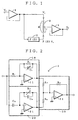
- Fig. 1 is a schematic circuit diagram of an embodiment of a loudness device according to the present invention.
- Fig. 2 is a concrete circuit diagram of a filter block in the embodiment of the loudness device.
- reference numeral 1 denotes a buffer amplifier; 2 a filter block; 3 a second synthesizer for synthesizing an input signal and a filter block output; and 4 a buffer amplifier.
- the second synthesizer 3 includes a sliding resistor, to both ends of which an input signal (Vi) and an output signal (F(s)Vi) from the filter block 2 are supplied. An output signal is produced from a sliding terminal of the sliding resistor, and supplied to the buffer amplifier 4.
- the filter block 2 as shown in Fig. 2, a low-pass filter (LPF) 10, a high-pass filter (HPF) 20 and a first synthesizer 30.
- LPF low-pass filter
- HPF high-pass filter
- the low-pass filter (LPF) 10 serves as a first order low-pass filter having a time constant of the values of the resistor R1 and capacitor C1.
- the cut-off frequency of the low-pass filter 10 can be varied by the capacitance of the capacitor C1.
- the high-pass filter (LPF) 20 serves as a first order high-pass filter having a time constant of the values of the resistor R2 and capacitor C2.
- the cut-off frequency of the high-pass filter 20 can be varied by varying the resistance of the resistor R2.
- the output from the low-pass filter 10 is supplied to an operational amplifier 31 through a resistor R3, the output from the high-pass filter 20 is also supplied to the operational amplifier 31 through a resistor R4, and the output from the operational amplifier 31 is fed back to the input thereof though a resistor R5 having a resistance equal to that of the resistor R3.
- the low-pass frequency band can be varied by varying the capacitance of the capacitor C1 of the LPF 10 ("A" in Fig. 3)
- the high-pass frequency band can be varied by the resistance of the resistor R2 of the HPF 20 ("B” in Fig. 3)
- the attenuation degree in the high-pass frequency band can be varied by varying the resistance of the resistor R4 ("C” in Fig. 3) of the first synthesizer 30
- the attenuation degree of the intermediate frequency band can be varied by shifting the sliding position ( ⁇ /R) of the sliding terminal of the second synthesizer 3 ("D" in Fig. 3).
Landscapes
- Tone Control, Compression And Expansion, Limiting Amplitude (AREA)
- Circuit For Audible Band Transducer (AREA)
Claims (3)
- Dispositif d'intensité sonore à caractéristique fréquentielle ajustable, incluant :caractérisé en ce queun filtre passe-bas (10) qui laisse passer une bande de basses fréquences d'un signal d'entrée,un filtre passe-haut (20) qui laisse passer une bande de hautes fréquences du signal d'entrée,un premier synthétiseur (30) pour synthétiser les signaux de sortie provenant du filtre passe-bas (10) et du filtre passe-haut (20), etun second synthétiseur (3) pour synthétiser le signal d'entrée et le signal de sortie provenant du premier synthétiseur (30) de manière à délivrer un signal de sortie synthétisé, ledit second synthétiseur (3) étant conçu pour assurer une atténuation variable de la bande de fréquences intermédiaires ;
la fréquence de coupure du filtre passe-bas (10) et la fréquence de coupure du filtre passe-haut (20) sont ajustables,
le premier synthétiseur (30) est conçu pour assurer une atténuation variable de la bande de hautes fréquences. - Dispositif d'intensité sonore selon la revendication 1, dans lequel ledit second synthétiseur (3) est une résistance réglable pourvue d'une borne réglable à partir de laquelle est collecté ledit signal de sortie synthétisé, la résistance réglable recevant, à une première borne, ledit signal d'entrée et, à l'autre borne, ledit signal de sortie provenant du premier synthétiseur (30).
- Dispositif d'intensité sonore selon la revendication 1 ou 2, dans lequel ledit premier synthétiseur (30) inclut :un amplificateur opérationnel (31),une première résistance fixe à travers laquelle est connecté ledit signal de sortie provenant dudit filtre passe-bas (10),une résistance variable à travers laquelle est connecté ledit signal de sortie provenant dudit filtre passe-haut (20), etune seconde résistance fixe ayant une valeur de résistance égale à celle de ladite première résistance fixe, à travers laquelle est réinjecté, à son entrée, un signal de sortie provenant dudit amplificateur opérationnel (31).
Applications Claiming Priority (2)
| Application Number | Priority Date | Filing Date | Title |
|---|---|---|---|
| JP32652998A JP3543929B2 (ja) | 1998-11-17 | 1998-11-17 | ラウドネス装置 |
| JP32652998 | 1998-11-17 |
Publications (3)
| Publication Number | Publication Date |
|---|---|
| EP1003285A2 EP1003285A2 (fr) | 2000-05-24 |
| EP1003285A3 EP1003285A3 (fr) | 2003-10-08 |
| EP1003285B1 true EP1003285B1 (fr) | 2005-08-31 |
Family
ID=18188862
Family Applications (1)
| Application Number | Title | Priority Date | Filing Date |
|---|---|---|---|
| EP19990122780 Expired - Lifetime EP1003285B1 (fr) | 1998-11-17 | 1999-11-16 | Filtre d'intensité sonore |
Country Status (3)
| Country | Link |
|---|---|
| EP (1) | EP1003285B1 (fr) |
| JP (1) | JP3543929B2 (fr) |
| DE (1) | DE69926973T2 (fr) |
Family Cites Families (3)
| Publication number | Priority date | Publication date | Assignee | Title |
|---|---|---|---|---|
| JPS6188327U (fr) * | 1984-11-14 | 1986-06-09 | ||
| JPH02222207A (ja) * | 1989-02-22 | 1990-09-05 | Matsushita Electric Ind Co Ltd | 聴覚補償装置 |
| JPH02118322U (fr) * | 1989-03-08 | 1990-09-21 |
-
1998
- 1998-11-17 JP JP32652998A patent/JP3543929B2/ja not_active Expired - Fee Related
-
1999
- 1999-11-16 DE DE69926973T patent/DE69926973T2/de not_active Expired - Lifetime
- 1999-11-16 EP EP19990122780 patent/EP1003285B1/fr not_active Expired - Lifetime
Also Published As
| Publication number | Publication date |
|---|---|
| EP1003285A2 (fr) | 2000-05-24 |
| JP3543929B2 (ja) | 2004-07-21 |
| JP2000152373A (ja) | 2000-05-30 |
| EP1003285A3 (fr) | 2003-10-08 |
| DE69926973D1 (de) | 2005-10-06 |
| DE69926973T2 (de) | 2006-03-09 |
Similar Documents
| Publication | Publication Date | Title |
|---|---|---|
| US4394536A (en) | Sound reproduction device | |
| US4119814A (en) | Hearing aid with adjustable frequency response | |
| US5305388A (en) | Bass compensation circuit for use in sound reproduction device | |
| US4797933A (en) | Bass amplifier with high frequency response | |
| JPH0683113B2 (ja) | 回線等化回路 | |
| EP1003285B1 (fr) | Filtre d'intensité sonore | |
| CN100539406C (zh) | 音频预放大器和中频带压缩器电路 | |
| US4326172A (en) | Tunable active high-pass filter | |
| US4331927A (en) | Noninverting amplifier circuit with low input impedance | |
| JP3308352B2 (ja) | 可変遅延回路 | |
| JPS6119189B2 (fr) | ||
| US20030090315A1 (en) | All pass filter | |
| SU1312723A2 (ru) | Усилитель низкой частоты | |
| KR830000245B1 (ko) | 주파수 특성 조정장치 | |
| JPH0421385B2 (fr) | ||
| SU1185573A1 (ru) | Тонкомпенсированный регул тор громкости | |
| JPS6237567B2 (fr) | ||
| JPH0738552B2 (ja) | 周波数等化回路 | |
| JPS6145638Y2 (fr) | ||
| SU1543567A1 (ru) | Устройство дл коррекции видеосигнала | |
| JPH054336Y2 (fr) | ||
| JPH05267964A (ja) | 帯域ブースト回路 | |
| JPS62190936A (ja) | 中継線等化器とその使用方法 | |
| JPH05291883A (ja) | 適応型フィルタ | |
| JPH02172311A (ja) | 帯域通過フィルタ装置 |
Legal Events
| Date | Code | Title | Description |
|---|---|---|---|
| PUAI | Public reference made under article 153(3) epc to a published international application that has entered the european phase |
Free format text: ORIGINAL CODE: 0009012 |
|
| 17P | Request for examination filed |
Effective date: 19991116 |
|
| AK | Designated contracting states |
Kind code of ref document: A2 Designated state(s): AT BE CH CY DE DK ES FI FR GB GR IE IT LI LU MC NL PT SE |
|
| AX | Request for extension of the european patent |
Free format text: AL;LT;LV;MK;RO;SI |
|
| PUAL | Search report despatched |
Free format text: ORIGINAL CODE: 0009013 |
|
| AK | Designated contracting states |
Kind code of ref document: A3 Designated state(s): AT BE CH CY DE DK ES FI FR GB GR IE IT LI LU MC NL PT SE |
|
| AX | Request for extension of the european patent |
Extension state: AL LT LV MK RO SI |
|
| 17Q | First examination report despatched |
Effective date: 20040405 |
|
| AKX | Designation fees paid |
Designated state(s): DE IT NL |
|
| GRAP | Despatch of communication of intention to grant a patent |
Free format text: ORIGINAL CODE: EPIDOSNIGR1 |
|
| GRAS | Grant fee paid |
Free format text: ORIGINAL CODE: EPIDOSNIGR3 |
|
| GRAA | (expected) grant |
Free format text: ORIGINAL CODE: 0009210 |
|
| AK | Designated contracting states |
Kind code of ref document: B1 Designated state(s): DE IT NL |
|
| REF | Corresponds to: |
Ref document number: 69926973 Country of ref document: DE Date of ref document: 20051006 Kind code of ref document: P |
|
| PLBE | No opposition filed within time limit |
Free format text: ORIGINAL CODE: 0009261 |
|
| STAA | Information on the status of an ep patent application or granted ep patent |
Free format text: STATUS: NO OPPOSITION FILED WITHIN TIME LIMIT |
|
| 26N | No opposition filed |
Effective date: 20060601 |
|
| PGFP | Annual fee paid to national office [announced via postgrant information from national office to epo] |
Ref country code: DE Payment date: 20091112 Year of fee payment: 11 |
|
| PGFP | Annual fee paid to national office [announced via postgrant information from national office to epo] |
Ref country code: NL Payment date: 20091114 Year of fee payment: 11 |
|
| PGFP | Annual fee paid to national office [announced via postgrant information from national office to epo] |
Ref country code: IT Payment date: 20091117 Year of fee payment: 11 |
|
| REG | Reference to a national code |
Ref country code: NL Ref legal event code: V1 Effective date: 20110601 |
|
| PG25 | Lapsed in a contracting state [announced via postgrant information from national office to epo] |
Ref country code: NL Free format text: LAPSE BECAUSE OF NON-PAYMENT OF DUE FEES Effective date: 20110601 |
|
| REG | Reference to a national code |
Ref country code: DE Ref legal event code: R119 Ref document number: 69926973 Country of ref document: DE Effective date: 20110601 Ref country code: DE Ref legal event code: R119 Ref document number: 69926973 Country of ref document: DE Effective date: 20110531 |
|
| PG25 | Lapsed in a contracting state [announced via postgrant information from national office to epo] |
Ref country code: DE Free format text: LAPSE BECAUSE OF NON-PAYMENT OF DUE FEES Effective date: 20110531 |
|
| PG25 | Lapsed in a contracting state [announced via postgrant information from national office to epo] |
Ref country code: IT Free format text: LAPSE BECAUSE OF NON-PAYMENT OF DUE FEES Effective date: 20101116 |